Ionization of Molecules at the CRYRING Facility
Licentiate Thesis Fabian Österdahl TRITAFYS 2006:42 ISSN 0280316X ISRN KTH/FYS/06:42SE
Stockholm Sweden 2006
2006-05-19 /home/norm/Desktop/Lic/FabLic1.1c.odt
Abstract Several techniques for producing molecular ions are used for experiments at the heavy ion storage ring CRYRING at the Manne Siegbahn Laboratory. In this thesis the development of ion sources based on the hot filament penning magnetron principle and hollow cathode glow discharge is described. The work has enabled measurements on several groups of molecular ions, that previously were difficult to produce in sufficient quantities and duration over time. The first measurements of the dissociative recombination with electrons of the cluster ion hydrated nitrosonium, NO+·H2O, and the deuterated isotopologue, NO+·D2O were done. The results indicate that the chemical branching population of the final products was: NO+HO+H NO •H2O + e > NO+H2O HO+HO+N H2O+O+N
80 ± 12 % 9± 8 6± 1 5± 4
% % %
NO+DO+D NO •D2O + e > NO+D2O DO+DO+N D2O+O+N
62 ± 2
%
21 ± 5 10 ± 4
% %
7± 5
%
+
+
The large degree of fragmentation into the three body channel was unexpected, indicating that some complex interactions are occurring within the temporarily formed neutral species.
20060519
Ionization of Molecules at CRYRING
1
Table of Content 1 Introduction..........................................................................................................................................3 2 Background...........................................................................................................................................3 2.1 Dissociative Recombination.........................................................................................................................3 2.2 Technical Requirements for DR measurements...........................................................................................5 2.3 The CRYRING Storage Ring.......................................................................................................................6 3 Ion Sources...........................................................................................................................................7 3.1 Ionization......................................................................................................................................................7 3.2 General IonSource Parameters..................................................................................................................7 3.3 Ion Sources Used at MSL............................................................................................................................8 3.3.1 The Nielsen-Type Hot Filament Penning Magnetron ...........................................................8 3.3.1.1 Principle of Operation....................................................................................................8 3.3.1.2 Construction...................................................................................................................9 3.3.1.3 Modes of Operation.....................................................................................................10 3.3.1.4 Characteristics..............................................................................................................11 3.3.2 Hollow Cathode Type Ion Source: Jimis.............................................................................14 3.3.2.1 Principle of Operation.................................................................................................15 3.3.2.2 Construction................................................................................................................15 3.3.2.3 Characteristics.............................................................................................................16 3.3.3 Hollow Anode Type Ion Source: Modified Jimis................................................................16 3.3.3.1 Construction.................................................................................................................17 3.3.3.2 Modes of Operation.....................................................................................................18 3.3.3.3 Characteristics.............................................................................................................18 3.4 Some observations on Ion Source Pulsing................................................................................................19 4 Dissociative Recombination of Hydrated Nitrosonium Ion................................................................21 4.1 Introduction ................................................................................................................................................21 4.2 Experiment.................................................................................................................................................23 4.3 Product Branching Ratios..........................................................................................................................25 4.4 Discussion..................................................................................................................................................27 5 Future Work........................................................................................................................................28 6 List of Papers......................................................................................................................................29 7 Papers not Included............................................................................................................................30 8 Contributions by the author................................................................................................................32 9 Thanks to............................................................................................................................................33 10 References.........................................................................................................................................35
20060519
Ionization of Molecules at CRYRING
2
1 Introduction Molecular ions are present in many different natural environments: interstellar space, dark clouds, planetary atmospheres, comas of comets, bolts of lighting, and in various industrial plasmas such as semiconductor fabrication and fusion reactors. In the atmosphere, ions are formed by ionization of neutral atoms and molecules mostly by solar UV radiation or cosmic rays. Molecular ions dominate the ion population below an altitude of 150 km, and the molecules become increasingly complex with decreasing altitude [1]. Ions may grow to large sizes by addition of gas molecules, which has been suggested to play an important role in cloud formation on Earth. The chemical reactions in such environments are often quite complex and dependent on many factors [1]. Laboratory measurements of individual processes are therefore needed, and should be made under conditions similar to the naturally occurring environment of the molecule [2]. The synchrotron and storage ring CRYRING [3] at the Manne Siegbahn Laboratory (MSL) in Stockholm is a suitable instrument for such studies. It has been used for experiments on molecules for more than a decade, resulting in a number of papers on specific molecular systems of importance for understanding the chemistry in the atmosphere. Since 1998 the author has been involved with the preparations for and technical support during most of the experiments on molecules at CRYRING. This paper describes some of the particular experiences and developments that have been achieved during this time. The paper is divided into three parts. In the first section, some theoretical background for the molecular investigations is given. In part two the developments of sources most often used for production of ions for molecular experiments at CRYRING, are described. Part three covers the measurement and analysis of data from one molecule with atmospheric relevance: the dissociative recombination with electrons of the cluster ions NO+•H2O and NO+•D2O.
2 Background Molecular ions undergo different kinds of reactions with other charged and neutral particles [4]. One process involves the attraction of free electrons towards positive molecular ions, where the excess energy is rapidly transferred in either excitations of a bound electron, or a vibrational state. In both cases, a highly excited neutral molecule is formed. This species will rapidly relax either by autoionization, ejecting an electron back into the continuum to produce an ion and a free electron again, or by breaking up into smaller parts, transferring the excess energy in to internal rotational/vibrational excitation and/or kinetic energy of the fragments.
2.1 Dissociative Recombination The joining of a free electron with a positive ion is called recombination, and the breaking-up of the molecule dissociation, hence: Dissociative Recombination, DR. This process was first postulated [5] by Kaplan in 1931, and described [6] by Bates in 1950. It is a complicated molecular reaction that only recently has become possible to theoretically model for simple molecular ions such as H2+ [7] and H3+ [8]. DR, being a very fast process, is the most important mechanism for neutralization in plasmas with low temperature and density, and the produced fragments have high kinetic energies. The DR reaction occurs with higher likelyhood the lower the initial energy of the incoming electron, approximately following an 1/E dependency, and the end products are neutral (molecular) fragments. If the incoming electron has kinetic energy approaching the ionization energy of one of the component fragments, however, the probability increases that one of the dissociating fragments is ionized, a process known as Dissociative Excitation, DE. If the incoming electron has even higher initial energy, more than one charged fragment can be formed, giving Dissociative Ionization, DI. 20060519
Ionization of Molecules at CRYRING
3
Fig. 1 shows potential energy curves for these recombination processes versus internuclear distance of a symbolic two atom molecule. (Reality is more complicated than this, with other intermediate mechanisms also leading to the same end products.)
Fig. 1: Potential energies as a function of internuclear distance for some processes a diatomic molecular ion might undergo when an electron of energy Ee-.hit the molecule. Solid curve: Dissociative Recombination; Dashed curve: Dissociative Excitation; Dotted curve: Dissociative Ionization. The probability for the different processes to occur is strongly dependent on the kinetic energy of the incoming electron, for simple energetic reasons. Fig. 2 shows the relative cross section for dissociation processes of N2+ [9,10], where the y-axis shows the cross section on a logarithmic scale for the different reaction processes versus incoming electron energy. The DR process is quite strong at energies close to zero eV while the maximum of the DE and DI processes are 10 000 times smaller (at some tens of eV).
Fig. 2: Cross sections relative DR at 1 meV for three different recombination processes of electrons with N2+ as a function of electron impact energy. During the years different experimental devices have been developed to study the interaction between 20060519
Ionization of Molecules at CRYRING
4
electrons and positively charged molecular ions undergoing recombination processes. Techniques such as microwave afterglow plasma [11], flowing afterglow [12], selected ion flow tube [13], and single pass merged beams [14] have been used. However, few are suitable to study interaction energies relevant for cold environments below 100 K, corresponding to electron energies below 10 meV. The internal states of the fragmenting products of the recombination process have also been difficult to characterize adequately. Another type of apparatus needed to be employed.
2.2 Technical Requirements for DR measurements The quality of the measurement of the electron recombination processes on a molecular system depends on many factors: a) The molecular ions have to be prepared with sufficient chemical purity, so that only the required species are present. b) The ions have to be prepared in sufficient intensities, allowing for beam diagnostics and transport through the apparatus. c) The ions have to be prepared with sufficient isomeric purity, so that the molecular configuration is the one of interest. d) Often the ions have to be prepared with a specific vibrational and rotational distribution, so that the internal state of interest can be characterized. e) The ions have to be kept in a sufficiently isolated reaction container, so that a beam can be extracted with a minimal interaction with background gas. f) Certain types of ions have to be given time to energetically relax, to allow low lying internal states to be studied. g) Some molecules are required to be actively cooled, so that interaction energies down in the meV range, similar to certain condition in space, can be studied. h) Sometimes the ions need to be excited, preparing them in a specific internal state of interest. i)
The ions have then to be exposed to a well defined probing stimulus, to study the particular reaction of interest.
j)
The products of the probing, in the form of photons or particles with a different mass to charge ratio than the parent ion, need to be analyzed with a detector system to determine the kinetic energy, spatial position and time of arrival.
k) Measurement of the ion beam current is often necessary, to obtain absolute values of the measured reaction rates. The problems regarding ion production a)-d) have been addressed through many decades of building devices for experiments on charged particles. It was only in the 1980s, however, that extra ultra high vacuum techniques, meeting requirement e), became readily available, making practical the construction of room temperature devices with a vacuum approaching 10-12 Torr, or 30 000 particles/cm3. At these pressures charged molecules with velocities above some 106 m/s have low enough interaction probability with the background gas to survive for several seconds. Charged particle storage rings, combining the good vacuum and high velocity requirements, give suitable characteristics to meet relaxation requirement f). The active cooling of g) has been achieved by merging the ion beam with a cool electron beam [15], reaching very low relative interaction energies. These electrons also give the opportunity for the excitation in h) and the probing in i), simply by changing the energy of the electron beam. Fragments from molecular ions with velocities above 106 m/s behave rather like particles investigated in earlier decades of accelerator experiments, so much
20060519
Ionization of Molecules at CRYRING
5
of the detector and diagnostic devices needed in j) and k) have been developed. The storage ring apparatus with accompanying equipment thus becomes an effective device for measurements of DR [16].
2.3 The CRYRING Storage Ring One storage ring meeting the above requirements was developed at the Manne Siegbahn Laboratory in the 1980s, namely CRYRING (for CRYogenic Ion Source connected to a storage RING). The cryogenic ion source [17] is an electron beam ion source capable of producing highly charged atomic ions, since CRYRING was designed for atomic and nuclear experiments. CRYRING, see Fig. 3, is a so-called synchrotron and storage ring, consisting of a 52 m circumference ring structure, built from 12 straight sections of 100 mm diameter stainless steel beampipe, pumped to a pressure below 10-11 mBar (or 7*10-12 Torr). Each corner has a rampable dipole magnet of 0.045-1.2 T with a 1.2 m radius for bending charged particles. Every second straight section has focusing magnets to keep the beam in place, and every other section a device for injection of beam, acceleration, cooling or for performing various experiments.
Fig. 3: The CRYRING storage ring Ions are produced in one of the several available ion sources, extracted, and -- if the charge/mass ratio is larger than 0.25 (rarely the case for molecules) -- pre-accelerated in a radio frequency quadrupole [18] to 300 keV/nucleon, before being injected into the ring. In the ring a high frequency electric field is applied in a 2.7 m long acceleration tube, grouping the beam into bunches. By increasing the frequency of the accelerating field, the ions are accelerated but are kept centered in the beam-pipe by a simultaneous increase of the dipole magnetic field. This is the synchrotron principle, and the magnetic field of the dipoles in CRYRING allows a maximum energy of E max=100∗
q² [ MeV ] m
to be reached, where q is the charge of the particle in units of [e], and m the mass in [AMU].
20060519
Ionization of Molecules at CRYRING
6
In 1992 it was proposed [19] to also use CRYRING for measurements on molecules, which has turned out to become a major use of the facility, especially after 1997 when greatly improved electron cooling [20] was introduced. Experiments on molecules at CRYRING have been described elsewhere e.g. [21], but a brief overview of the procedure is given in section 4.2.
3 Ion Sources In order to study atoms or molecules in gas phase, it is often advantageous to isolate the particles in vacuum during extended periods, allowing relaxation of internal energy and the exposure to external state-preparing and probing fields. Techniques [22] are being developed to manipulate polarized neutral molecular species over macroscopic distances and times, using electric fields, but it is by far easier to accelerate and transport ions in electric and magnetic fields, using accelerator techniques that have been refined during the last century. As the goal of the present work is to study molecular ions, it is more effective to produce ions at an early stage. An overview of some ion sources for molecular experiments, with examples from two of the sources commonly used at MSL, is given next. For detailed descriptions, see the excellent compilation [23] by Wolf, covering many aspects of ion sources and accompanying techniques.
3.1 Ionization The process of removing electrons from an atom or molecule is called ionization. Ionization can be accomplished for example by: •
Electron impact, where a free electron knocks out one or many bound electrons from a neutral atom or molecule;
•
Ion impact, where a free high velocity ion strikes a neutral atom or molecule, ejecting an electron (or more than one, if conditions are right) from the neutral, making a new ion and (at least) a free electron;
•
Penning ionization, where an electronically excited neutral atom in a collision exchanges an electron with an other neutral atom or molecule with lower ionisation potential than the incoming excited neutral, leaving an ion and a free electron in the process;
•
Surface ionization, where atoms or molecules with a comparably low ionisation potential reach a hot surface with a high work function, thermally kicks out an electron from the neutral.
•
Photo ionization, where an energetic photon directly ejects an electron from a neutral molecule;
•
Field ionisation, where a strong electric or magnetic field removes an electron from an atom or molecule;
Ionization is most conveniently carried out on neutral atoms or molecules in the gas phase, creating a mixture of neutral gas, ions, and free electrons, called a plasma. By applying an electric field to this plasma, ions can be extracted into a beam.
3.2 General IonSource Parameters Ion sources are characterized by several qualities such as attainable ion currents, the possible ion species that can be produced, and several beam quality parameters such as the stability, divergence and energy spread of the extracted ion beam. There are also secondary aspects of practical importance, such as ionization efficiency of the originating medium, running time between servicing, 20060519
Ionization of Molecules at CRYRING
7
load on the surrounding vacuum pumps and high voltage systems.
3.3 Ion Sources Used at MSL The ionization process most often used in ion sources is electron impact ionization, because of the ease with which electrons can ionize when accelerated even by moderate electric fields. The kinetic energy of the ionizing electron must be greater than the ionization energy of the neutral species, typically some 10-20 eV; most efficient ionization typically occurs at about three times the ionization energy. The electrons can be produced by a dedicated device, e.g. by thermionic emission from a hot surface, forming so-called primary electrons, or be generated in the ionization process of the gas, making secondary electrons. The accelerating electric field is easily obtained by applying a voltage between two conducting surfaces, suitably oriented to produce the ionized plasma. The atoms or molecules to ionize can be admitted as straight gas such as N2,vapor from a liquid such as H2O, or from a room-temperature solid such as Li, heated in an oven to make gas by evaporation. For electron impact ionization the following are therefore required: free electrons; an electric field to accelerate the electrons to sufficient energy; an atomic or molecular gas to ionize; an environment where the produced ions can survive; and a vacuum chamber and accelerator system to produce a useful beam for transport to the interaction region. At MSL the molecular ions are produced by a number of different types of sources. The most common are: Hot filament Penning magnetron – Nielsen type [24], similar to the Danfysik model 910; Hollow anode glow discharge – “Jimis” [23]; Super-sonic expansion [25]; Caesium sputter, a Peabody model PS 120 [26]. Other types of sources are used less frequently: Electron impact NIER type“Philis” [27]; Hollow anode sputter - Baumann [28]; Hollow cathode hot filament type Sidenius [29]. For molecular experiments at CRYRING, the sources are installed on the separator platform MINIS, which provides a mounting tube with an externally located solenoid, generating an axial magnetic field of up to 30 mT centered on the source, several gas/vapor channels, a + 40 or - 40 kV acceleration gap, an Einzel lens for focusing, vacuum meter, etc. Downstream of the source, the ions are mass selected by a dipole magnet and the current of the beam can be measured in a Faraday cup, or transportet further into the storage ring. A general overview of the principles of operation and performance of the Nielsen and Jimis ion sources follows below.
3.3.1 The NielsenType Hot Filament Penning Magnetron The ion source most frequently used for low charge state ion beams at MSL is a Nielsen type [24] Hot filament Penning magnetron. The Nielsen source has proven to be a dependable work-horse, capable of making intense beams of many species for several days running between servicing. 3.3.1.1 Principle of Operation The Nielsen source can be operated in a number of different modes, depending on what the requirements are. The ionization is usually initiated by electrons from the centrally located filament cathode, see Fig. 4, electrically heated above 2000°C. The electrons are extracted from the filament surface by the anode voltage and are radially accelerated out towards the surrounding anode. A solenoid magnetic field crosses the electron velocity vector, giving rise to a Lorentz force F = qv x B perpendicular to the velocity, causing the electrons to undergo a spiraling motion, radially confined to the center of the source. The end caps are held at (almost) the same potential as the filament, so axially there is little electric field, making the electrons free to move along the entire axis of the
20060519
Ionization of Molecules at CRYRING
8
source. The effective path length therefore becomes substantial, making the Nielsen source a very efficient ionizer of gases.
Fig. 4: Principle of the Ionization in a Penning Magnetron One end cap has a small central hole, through which the ions are extracted by the acceleration voltage. 3.3.1.2 Construction In the MSL version of the Nielsen source, the anode is 25 mm diameter, 50 mm long cylindrical made from Molybdenum, see Fig. 5. The filament is made of Tantalum or Tungsten, 0.5 to 1.1 mm diameter. The diameter of the extraction hole is between usually around 1 mm. The solenoid, mounted outside the vacuum chamber, makes an axial magnetic field of up to 30 mT. The source was originally intended for ionization of metals, so some attention was given on its construction out of heat resistant materials and providing heat shielding, allowing the entire assembly to reach over 1000 °C.
Fig. 5: The MSL Nielsen type Ion source - Schematic diagram 20060519
Ionization of Molecules at CRYRING
9
The effective electron current from a 0.7 mm Tantalum filament as a function of anode voltage for different heating powers (and hence temperatures) of the filament is depicted in Fig. 6. It can be seen that by varying the heating of the filament and the voltage of the anode, the number of extracted electrons and their energy can be independently controlled over a wide range – just what is required in an ion source. At higher heating powers (upper curves) there is an abrupt increase (log scale!) and saturation in the anode current for voltages above approx 70 V, indicating that the density of electrons has reached its space-charge limited maximum.
Fig. 6: Nielsen source: anode electron current versus anode voltage for filament heating powers from 66 W (lower trace), to 192 W (top trace). When a gas is admitted into the discharge chamber, the electrons from the filament can ionize the gas, if the anode voltage, and hence electron energy, is higher than the ionization energy of the gas. The generated positive ions form a plasma, drifting towards the negative filament and end-caps. When ions approach the extraction hole the acceleration voltage starts pulling out a beam. 3.3.1.3 Modes of Operation The Nielsen source can be operated in three distinct pressure regions: •
An electron impact mode is characterized by low internal pressure, making the average mean free path-length of the gas particles longer than the dimensions of the source. The generated ions rarely hit other molecules, so the plasma mostly consists of ions from the initial electron impact. This mode therefore offers some control of the energy of the ionizing electrons, which is suitable e.g. when a gentle ionization is desired, without causing much breakup of the initial neutral molecule and risk of secondary ion or isomer contamination. The currents attainable from this mode are often quite feeble, in the nA range.
•
In the secondary plasma mode, more gas is admitted making the mean free path between collisions in the gas shorter than the dimensions of the discharge chamber. This means that secondary ionizations in the plasma becomes more frequent, both from excited primary ions and secondary electrons from the ionization process. Intense ion beams can be produced, reaching hundreds of µA extracted current. This is the usual way of operating the Nielsen source.
•
The Nielsen source can be operated in a cold glow discharge mode, driving the plasma with a high voltage on the anode, while reducing or totally disconnecting the power to the filament.
20060519
Ionization of Molecules at CRYRING
10
By pulsing the discharge voltage via a small current limiting resistor, instantaneous anode currents of over 1 A and voltages falling below 100 V have been seen, indicating that a more arc-like discharge is forming. This mode of running is useful for producing ions of oxidizing or sooting gases that otherwise would quickly consume the filament, or leave short-circuiting deposits on the insulators.
In table 1 the approximate pressure ranges used at MSL for the different operational modes are listed. Mode
Internal Source Pressure [mTorr]
External Pressure MINIS [µTorr]
Electron Impact
.01 > 1
.1 > 3
Secondary Plasma
1 > 100
3 > 100
Glow Discharge
10 > 1000
10 > 400
Table 1: Nielsen source, internal pressure for different modes of operation.
3.3.1.4 Characteristics The general characteristics of the Nielsen source has been thoroughly investigated previously, so only some aspects of relevance to the ionization of molecules will be mentioned here. Beam Currents The Nielsen source operated in secondary plasma mode has been used for a large number of molecular experiments at MSL. In table 2 are some examples of currents obtained.
Ion 3 He+ N 2+ NO + N+ OH+ H 3+ H 2O + H+
Current[nA] 33000 30000 20000 12000 12000 5500 4000
Ion Current[nA] 4 HeH+ 2700 + CO 1300 86 + Kr 1000 C 2H 2+ 500 + CH5 300 + LiH2 47 + CH3OH2 10
2900
Table 2: Nielsen source, some ion currents in secondary plasma mode The hot filament in the secondary plasma mode is subject to sputtering from positive ions, and also degrades quickly by the action of any oxidizing species in the gas. The filament-less glow discharge mode was found by accident at a time of broken filament. This mode turns out to have rather good performance and has been useful several times, when the gas to ionize has a high content of oxygen, and also for most other non-condensing gases due to the increased long time stability of operation 20060519
Ionization of Molecules at CRYRING
11
without filament. Some obtained currents in the glow discharge mode are listed in table 3.
Ion Ne+ H 3O + He+ pH2+ 3
H13CO+ C 2D 5 O + 11 BH2+
Current[nA] 30000 16000 15000 8500 3100 1000 130
Ion Current[nA] + CF 40 13 + CD3OD2 25 + CO2 20 + CF 3 15 + O3 14 H'2S+ 4 CF 2+ 2.5
Table 3: Nielsen: some ion currents obtained in glow discharge mode Experiments using the Nielsen source run in the glow discharge mode include CO2+ [30], CF+ [31], CF2+ and CF3+[32], and NaD2O+[33]. Temperature As a result of the electron impact ionization process, the molecular ions are generated in a mixture of highly excited states, both vibrationally and rotationally, with temperatures corresponding to several thousand Kelvin. The source pressure of over 10 mTorr means that the ions, before being extracted, undergo many collisions with neutrals in the plasma. Some rotational deexitation then occurs, and the ions will generally acquire a rotational temperature corresponding to the temperature of the source. Molecules with a small dipole moment, e.g. homo nuclear molecules, cool by radiative emission only slowly, compared to the storage time in CRYRING (minutes for light molecules to seconds for heavier species), and such molecules therefore maintain the ro-vibrational state initially obtained from the ion source. The kinetic energy release from the DR process is dependant on the excitation state of the initial molecule, so by imaging the fragments on a position sensitive detector [34] located about 6 m from the electron cooler, the ro-vibrational state of the beam can be deduced. For the secondary plasma mode a rotational temperature of about 1000 K was seen for N2+ [35]. Vibrational deexitation is not an efficient process at these pressures, so the Nielsen source generally produces molecules with some vibrational excitation, e.g. up to vibrational quantum number v = 3 for N2+ [36]. Excitation To characterize the effect on molecular excitation from the hot secondary plasma and glow discharge modes of running the Nielsen, experiments were done to measure the distances between the fragments from the DR of para-H2+, collected after about 30 seconds of electron cooling. In Fig. 7 the top curves represent the original data, and the solid curves the distance projections from the vibrational states of p-H2.
20060519
Ionization of Molecules at CRYRING
12
Fig. 7: Nielsen source – Interparticle separation between the neutral H atoms from the DR of para-H2+ produced in the secondary plasma, left plot, and the glow discharge modes, right, modes of operation. Top traces are the collected data, bottom traces the fitted distance projections from vibrational states v = 0 to 3. Preliminary proportions between the vibrational levels were the following: Secondary plasma Glow Discharge
v = 0 1 1
v = 1 3.0 2.2
v = 2 1.3 0.8
v = 3 0.8 0.9
It seems clear that the molecules produced in the glow discharge mode are substantially less excited. (The statistics for the large distance data was poor for the glow discharge mode measurement, making the v = 3 value uncertain.) Beam Quality As a comparison of the beam quality moving from the secondary plasma towards the glow discharge modes, in Fig. 8 is plotted the effective beam area (diamond symbols) as seen on a 2D strip detector 4 m downstream the source versus the initial discharge voltage.
20060519
Ionization of Molecules at CRYRING
13
Fig. 8: Nielsen source – Beam current, left y, and minimum beam area, right y, as a function of initial discharge voltage, measured on a position sensitive strip detector 4 m downstream the source. The internal pressure was about 40 mTorr and the magnetic field 30 mT. The filament was adjusted for maximum beam intensity (triangle symbols) for each anode voltage setting (except for the 1500 V value, where the maximum ion current saturated the detector). The einzel lens after the sourse was tuned to give minimum spotsize for each datapoint. The strip detector was gated for 2 ms, the typical time for injection of heavy particles into CRYRING. At an anode voltage of 50 V the spotsize was about 900 mm², decreasing to less than 50 mm² for an initial anode voltage of 1500 V. This might indicate that the glow discharge mode reduces the divergence of the beam, perhaps by lowering the energy spread in the discharge plasma. Operating Lifetime To obtain high ionization in the secondary plasma mode, the filament has to be maintained at high temperature to generate much electrons. The materials usually selected, Tungsten or Tantalum, handle operating temperatures above 1500 °C, but are affected by sputtering from the positive ions in the plasma, limiting the effective operational life to a couple of days. When the medium to ionize contain oxidizing elements, the elements W or Ta readily react, shorting the life-time further. The internal insulators are sensitive to being coated by conductive deposits, also reducing the effective running time e.g. for making carbon or metal containing molecules. The effect of oxidation and shortening deposits can be reduced by pulsing the gas and discharge voltage, but long time stability is not so good due to the changing behaviour of the filament. Therefore the secondary plasma mode is most suitable for “gentle” gases, specially when very large beam currents are required. The glow discharge mode, however, suffers no degrading from oxidizing gases, and once a suitable working point is found, show good long time operational stability.
3.3.2 Hollow Cathode Type Ion Source: Jimis Many molecules need to be studied in a specific internal energy state, often the ground state, corresponding to the temperature of the natural environment of the molecule. The Nielsen source, operated in the hot secondary plasma mode produces, as we have seen, ro-vibrationally excited ions. Molecules with a nonzero dipole moment will cool by emitting IR radiation during a few seconds of storage in CRYRING. However, several interesting homonuclear molecules, such as N2 and O2, have 20060519
Ionization of Molecules at CRYRING
14
no dipole moment, and hence after leaving the source stay hot for long times. One way to obtain relaxed molecular ions is to collide them with cold neutral gas at reasonably high pressure, allowing the hot molecules to transfer internal energy in collisions with the neutral gas, either through direct vibrational relaxation, or through charge transfer [37]. 3.3.2.1 Principle of Operation A discharge can be produced by applying a high voltage across electrodes with a gas in the range of mTorr to Torr in between, see Fig. 9.
Fig. 9: Principle of glow discharge ionization. A high voltage is applied between two electrodes with a gas in between, causing a breakdown, and a beam can be extracted through the cathode. If the discharge power is kept low, a weakly ionized, cold, plasma is formed, and ions having experienced hundreds of collisions with the neutral gas can be extracted, usually through the cathode. This is the principle of the Jimis source. 3.3.2.2 Construction The Jimis source was built according to a design from SRI International, California, USA, which in turn was based on a model [38] developed at University of Freiburg, Germany. The source, see Fig. 10, consists of a discharge chamber 75 mm length and 12 mm inner diameter.
Fig. 10: Jimis, original construction The rear electrode, made from aluminum, has feed-tubes for the gases to be ionised, and is usually kept at ion source ground potential. A central electrode, made from stainless steel, 40 mm in length, 20060519
Ionization of Molecules at CRYRING
15
forms the anode, and is usually kept close to ground potential. The forward electrode is the cathode, also from stainless steel, usually connected to the negative terminal of the discharge voltage supply via a current limiting resistor. The cathode is water cooled to keep the plasma cold. The outlet aperture of 0.1 – 1 mm diameter, located 5 mm in front of the cathode, is made in a circular disk of metal (usually Cu or W) of 0.1 – 1 mm thickness. The whole assembly is pressed together between ceramic isolators sealed with O-rings, in order to retain the internal gas pressure. At the rear end a window allows inspection of the plasma. 3.3.2.3 Characteristics The original Jimis was usually operatedwith an internal pressure up to 1 Torr, and a cathode voltage of about 400 V at < 10 mA. The source magnetic field did not have any beneficial effect on the beam intensity. Beam Current The source was used at MSL in 1997 and 1998 for experiment on the DR of N2+ [36], O2+ [39], and relatively weak beams of currents mostly below 100 nA were achieved, see table 4.
Ion N 2+ Ne+ O 2+ CH3OH+ H 3O + He2+ C 2H 4 +
Current[nA] 900 360 145 70 40 32 29
Ion C 2 H5 + C2OH+ O+ H5O 2+ Ne2+ He+ O 3+
Current[nA] 27 27 16 9.1 7.9 6 0.2
Table 4: Original Jimis, Examples of maximum ion currents obtained between 1997 and 1999. Temperature and Excitation The source gave for N2+ a rotational temperature of 300 K and vibrational levels up to v=3 were populated [36].
3.3.3 Hollow Anode Type Ion Source: Modified Jimis To get large ion currents in ion sources, a large ionization volume is often strived for. However, when the plasma was examined through the inspection window in the original Jimis, bright spots could sometimes be seen, forming spontaneously in the discharge chamber, and remaining stationary in position and intensity for extended times. These hot-spots were thought to disturb the plasma and thus the production of ions, so the operational settings were usually changed to remove the spots. If that did not work, the source had to be opened, and the inside polished, a frequent maneuver with the original Jimis. But after detailed investigations trying various combinations of parameter settings, with typical ion currents of only a few nA out of the source, the author got the idea: perhaps such a bright spot could be useful. The principle would be to generate a spot close to the source outlet, such that any ions produced in the spot would be extracted.
20060519
Ionization of Molecules at CRYRING
16
3.3.3.1 Construction The aim then was to shape the electrodes such that the plasma would be concentrated at the outlet. This was done by shielding most of the metal outlet disk, except the very outlet hole, with a mica insulator of < 0.3 mm thickness, see Fig. 11, in effect making the outlet hole the anode of the discharge. The original anode was usually left electrically floating.
Fig. 11: Jimis, new configuration - Detail A similar and more elegant source [40], has been developed in 1990 by Miljevic, who reported obtaining currents over 100 µA. The full connection schematics of the modified Jimis source is shown in Fig. 12.
Fig. 12: New Jimis: overall schematics
20060519
Ionization of Molecules at CRYRING
17
3.3.3.2 Modes of Operation The modified Jimis can be run in different modes, again depending on the requirements. •
At pressures below about 0.1 Torr, a voltage of about 2 kV on the cathode is required for ignition. The resulting plasma is diffuse, as seen through the inspection window, with extracted ion currents of a few nA.
•
Increasing the pressure to 0.3 Torr leads to a sudden shift in the position of the plasma, making an intense glow at the extraction hole, and the internal discharge voltage drops to about 400 V.
3.3.3.3 Characteristics Glow discharge ion sources are often used in industri for ion implanting etc., and have been subjected to innumerable studies over the years. Here will therefore only some observations pertaining to the generation of molecules be described. Beam Currents The modified Jimis makes beams of higher intensity than the original version. Table 5 shows a list of some ion currents which have been obtained. Ion H 3+ D13CO + H 2+ CH3OH2+ CH3O+ ND4+ NO+ CD3OD2+ CH3OH+ H 3O + He+ O 2+ H 2O +
Current[nA] 20000 12000 8000 6700 5000 5000 5000 4000 1800 1500 1100 900 750
Ion Current[nA] + CD3OD 700 + CH2 500 3 + (CD )2OD3 400 + (ND3)2D 350 + CH3SSCH4 350 3 + (CD )2OD3 280 H13CO+ F+ (CD3)2O+ H5O 2+
250 200 190 180
Kr+ H7O 3+ CD3OH2+
160 130
83
Ion Current[nA] + (CD3)2OD 60 + C 3D 3 60 H 9O 4+ 60 + • NO H2O 60 C 6D 6+ 52 + (ND3)2D 35 + H 9O 4 35 + O3 30 + H 9O 4 20 + D5 2 + (NO)2 1 + H11O 5 0.7 + H13O 6 0.1
100 Table 5: Modified Jimis, examples of ion currents obtained on a Faraday cup after the source. Usually little effort is put in making intensities above a few hundred nAs, the required amount for conveniently injecting a beam into the storage ring. For most measurements on molecules, beam currents of about 100 nA is sufficient. The solenoid magnetic field has an influence to concentrate the plasma radially in the source, and contrary to the experience with the previous version of Jimis, often increasing substantially the resulting ion current. Several of these ions have been used in experiments on dissociative recombination, e.g. H2O+ [41], D2O+, D3O+ and H3O+ [42], D+•(D2O)2 [43], O2+ [44], NO+ [45], (NO)2+ [46], H3+ [47], NH4+ [48], and HCNH+ [49]. 20060519
Ionization of Molecules at CRYRING
18
3.4 Some observations on Ion Source Pulsing The operation of CRYRING is in a shot to shot fashion, each ion injection taking less than 2 ms, separated by several seconds of acceleration, storage and measurement. It therefore makes sense to also operate the ion sources in non-continuous mode. The efficiency in the ion production was actually found to be greatly improved by operating the sources in pulsed fashion, compared to the traditional steady state. Pulsing has turned out to be an especially useful technique for making complicated or weakly bound molecular ions. A gas admission valve used for many years is an externally mounted Sirai model Z030C w2.5. Fig. 13 shows the current of the cluster ion NO+·(H2O)2 from the modified Jimis. The top trace is the control pulse opening the gas valve admitting NO for about 150 ms into a continuously burning plasma of H2O, the bottom trace is the resulting ion current of approximately 6 nA in the Faraday cup.
Fig. 13: Ion source gas pulsing for producing the cluster ion NO+* (H2O)2. Upper trace: control signal for the admission of NO gas versus time [Horizontal 1 s/div]; Lower trace: Resulting ion current [Vertical 1 nA/div]. Turning on the discharge voltage only for a short time allows a temporary high discharge current, often substantially increasing the ion current generated compared to what is possible in a continuous discharge mode. Fig. 14 shows a measurement of a pulsed beam form the Nielsen source of N2+.
Fig. 14: Nielsen ion source, gas and discharge pulsing for N2+. Upper trace: control signal for the admission of N2 gas [Horizontal 100 ms/div]; Second trace: gas pressure, about 40 µTorr max; Third trace: discharge gate; Fourth trace: resulting ion current [Vertical 5 µA/div]. At first the gas is admitted (upper trace) during 100 ms, making the pressure (second trace) outside the source rise to about 40 µTorr. Then the dischare is ignited (third trace), producing about 12 µA 20060519
Ionization of Molecules at CRYRING
19
beam (lower trace). Different brands of high voltage relays have been used, recently a 10 kV 5 A hot switching type G81B from Gigavac. Discharge pulsing voltages above a few hundred volts with the present unregulated supply of current does sometimes reduce the length of the ion pulse produced compared to the broad pulse in Fig. 14, but the length of the injection pulses for CRYRING have only to be between 0.1 and 2 ms long. The present bulky flow control system means that some tuning is required in going from short (< 1 sec) to long (>10 sec) cycles. To provide control of the individual ion source timing relationships, timing control hardware was therefore connected to the general CRYRING electronics. Typical timing relationships and lengths are shown in Fig. 15 but the settings are optimized according to the requirements for the particular ion.
Fig. 15: Ion source pulsing timing relationships typically used at CRYRING. Previous Cycle Stop triggers the local ion source electronics, that in turn open the gas, Gases 1,2, and initiate the Discharge. At this time the Cryring T0 is sent out, and the next injection is initiated. Times are in ms. Ion source pulsing reduces greatly the gas load on the pumping system, wear from sputtering on the filament, and build-up of deposits on the insulators, especially for machine cycles longer than about a second. For the Jimis source, pulsing has meant that the need for active cooling of the cathode with water is eliminated. Both the Jimis and Nielsen sources are now commonly operated in pulsed mode, and several of the ions listed in Tables 3 and 5 would have been difficult to produce otherwise.
20060519
Ionization of Molecules at CRYRING
20
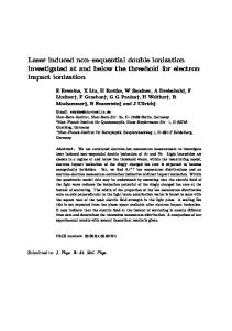
4 Dissociative Recombination of Hydrated Nitrosonium Ion 4.1 Introduction Nitric oxide, NO, is an important molecule in earth's atmosphere. NO has a low ionisation potential of ~9 eV (compared with other common diatomic molecules: 16 eV for nitrogen, 12 eV for oxygen and 15 eV for hydrogen), and is ionized by solar UV radiation, by charge transfer reactions from other ions such as O2+or N2+, or formed in ternary collisions such as N+ + O + M [50]. NO+ becomes one of the most common molecules in the upper atmosphere E and F layers, at approximately 90-300 km altitude. At lower altitudes of ~60-85 km NO+ is believed to undergo a series of reactions with N2 or to a lesser extent with other neutral molecules such as CO2 or H2O, leading to the forming the molecular cluster ion, hydrated nitrosonium, NO+·H2O, see Fig. 16 adopted from [51]. The NO+·H2O ion is an important early intermediate species in the atmospheric molecule formation processes, and the main destruction mechanism is thought to be dissociative recombination [50].
Fig. 16: Formation and destruction of NO+·H2O in atmosphere (with permission from the authors in [51]). To explain the effect on electron ion and neutral molecule concentrations in the atmosphere, the recombination of NO+·H2O with electrons therefore needs to be studied. When electrons recombine with NO+·H2O, a total of 20 neutral product channels are possible, and those are listed in Fig. 17. To determine which channels are exothermic, and hence energetically allowed, the excess energy of each reaction was computed from the heat of formation of the parent ion and the product fragments in their ground electronic and vibrational state. This showed that all the four and five body channels and the channel HO+O+O (o) were endothermic, reducing the number of energetically allowed channels to 14.
20060519
Ionization of Molecules at CRYRING
21
Channel KER[eV] NO HON NO 2
H2O
HONO O2
H H2N
HONH H2O 2 HO 2
NH
8.46 8.36
(c) (d)
6.54 5.42
O
(e) (f)
4.91 3.55
N
(g)
3.4
(h)
2.96
O
H2
(i)
3.37
> NO NO 2
HO
H
(j)
3.29
H
H
(k)
2.02
H2O
O OH O
N N NH
(l) (m) (n)
1.91 1.18 0
O O
O H
H
(o) (p)
0.25 1.15
N O O O
H N O N
H H H H H
(q) (r) (s) (t)
2.53 3.26 4.44 7.7
NO NO +•H2O + e
(a) (b)
OH H2
OH OH H2N NO O2 OH NH O
Fig. 17: The different branching channels for NO+·H2O + e- with the corresponding kinetic energy release (KER) for the fragments in ground state. The shaded channels (o) to (t) are not energetically allowed. From ab initio calculations, NO+·H2O has been reported [52] to have three stable isomeric forms: one planar with the NO bent parallel with the water, and one three-dimensional with the oxygen of the NO bent towards the middle of the two hydrogens in the water, see the top two structures in Fig. 18. The positive charge was located mainly on the nitrogen atom.
Fig. 18: Stable isomers of NO2H2+ as computed in [52]. The calculations also indicated that a third form HON+OH, protonated nitrous acid, is stable, having an energy 1.5 eV higher than NO+·H2O. This isomer might lead to e.g. channel (m) in Fig. 17, and prompts further investigation.
20060519
Ionization of Molecules at CRYRING
22
4.2 Experiment Two experiments studying the DR of the cluster ions NO+·H2O and NO+·D2O were carried at the storage ring CRYRING, at the Manne Siegbahn Laboratory, Stockholm. The ions were produced in the modified Jimis ion source, using a mixture of 0.8 Torr NO and 0.5 Torr H2O and D2O gases, thereafter accelerated to 40 keV and mass selected with a separator magnet. Efficient formation of the cluster ions was quite sensitive to the NO-pressure, indicating that there were many processes taking place in the plasma. At the optimal working point, the mass spectrum, see Fig. 19 for the hydrogen system, showed water with accompanying clusters (H2O+, H+·(H2O), H+·(H2O)2, H+·(H2O)3 and H+·(H2O)4) and NO+, NO+·H2O and NO+·(H2O)2.
Fig. 19: Mass spectrum from the modified Jimis source for an optimized beam of NO+·H2O.(The lower background for the low intensity peaks above mass 30 is because there a less noisy and more sensitive range on the Faraday cup amplifier was used). The mass spectrum contained NOH+ and OH+ at only 10 nA, compared to the 100 nA of H2O+ and 1000 nA of NO+, and it showed no H+ or HONO+. This suggested that the isomeric form HON+OH had a low abundance in the plasma. The ions were injected and stored in the ring, accelerated to 2.0 MeV (1.92 MeV for the deuterated system) total energy, and merged with an 85 cm electron beam of the same velocity and a 0.1 meV longitudinal and 2 meV transverse energy spread. The beam coasted for six seconds, allowing any remaining vibrational excitations from the source to decay to the ground state, and perhaps giving some phase space cooling [20] to the beam. Neutral fragments generated in recombination events went straight through the bending magnet after the electron cooler, were after seven seconds a beam stopper opened for one second, permitting the fragments to travel further to the detector system about 4 m from the center of the cooler. The particles first encountered a grid, giving each fragment a probability of 0.297±0.005 to continue further. After the grid a 900 mm² energy sensitive ionimplanted detector (Ortec type BU-055-900-300) generated pulses corresponding to the total energy of the incoming particles, see Fig. 21. The pulses were amplified and shaped, and finally accumulated in pulse height spectra on a data acquisition computer.
20060519
Ionization of Molecules at CRYRING
23
Fig. 20: Detector setup for the branching ratio determination. Each particle has a probability of 0.297+-0.005 to pass the grid, generating a signal amplitude proportional to sum of all the particles that reach the detector.
Recombination with electrons is not the only way the circulating ions were destroyed, however, as reactions with the residual gas, mostly H2 at about 10-11 Torr, in the the ring also created some neutral fragments. To remove the data from these events, separate spectra were recorded with the electrons turned off, allowing only the background events to reach the detector. After normalization taking into account the beam current, the background contribution was subtracted from the raw DR data, making the real DR spectra. Fig. 20 plots such data for the hydrogen system.
Fig. 21: Raw DR + background data taken at zero eV electron impact energy , top trace; Background data with electrons turned off, lowest trace; Real DR data remaining in the middle trace. The same procedure was applied to the deuterated system.
20060519
Ionization of Molecules at CRYRING
24
4.3 Product Branching Ratios The pulse height spectrum should have one peak for each unique sum of masses for each DR event. The puls height spectrum for the hydrogen system, see Fig. 22, showed three main peaks, corresponding to the combination of heavy N and O fragments in the molecule, with one or two hydrogen masses added to the right. Detection sensitivity was not sufficient, however, to show any signal from H or H2 alone. By knowledge about the position of each mass, it was possible to fit modified Gaussian distributions to each distinct mass. Summing the areas gave the number of particles for each mass.
Fig. 22: Energy spectrum for NO+·H2O + e-, background subtracted. Original data black; fitted gaussians in gray; sum of the fits, dashed. The deuterated species NO+·D2O gave the pulse height spectrum shown in Fig. 23, which was rather more well resolved.
Fig.23: Energy spectrum for NO+·D2O, background subtracted. Original data black; asymmetric gaussians in gray; sum fit dashed.
20060519
Ionization of Molecules at CRYRING
25
As each product channel consist of (mostly) distinct combinations of masses. This leads to a probability, P, linking the observed number of events for each mass, Npeak, with the number of events for each dissociation channel, NChannel: N Peak=P x N Channel
which can be solved for NChannel, after normalization, giving the fraction of events per channel, i.e. the chemical branching ratio. The hydrogen cluster seemed to give no contribution for mass 46, NO2, and the deuterated spectrum certainly had no mass 4, D2, resulting from fragments D + D or D2, indicating that channels (c, i, k, p, q and t) are unpopulated for both systems. The remaining linear system was solved with the open source Octave package, giving the branching fractions displayed in the upper plot of Fig. 24. It can be seen that channel (j) dominates at over 80%.
Fig. 24: Upper plot: Branching fractions [%] for all populated exothermic channels in the DR of NO+·H2O; Lower plot: The fitted data areas, squares, and branching fractions from upper plot, multiplied by probability matrix P, stars. The lower plot shows the fitted areas of the original data with squares, and a simulated mass spectrum computed from the obtained branching fractions, plotted with stars. The final branching fractions for the two DR reactions are displayed in Fig. 25. NO+OH+H NO +•H2O + e > NO+H2O OH+OH+N H2O+O+N
(j)
80 ± 12 %
(a) (m)
9± 8 % 6± 1 %
(l)
5± 4 %
NO+OD+D NO+•D2O + e > NO+D2O OD+OD+N D2O+O+N
(j)
62 ± 2 %
(a) (m)
21 ± 5 % 10 ± 4 %
(l)
7 ± 5 %
Fig. 25: Final chemical branching ratios for NO+·H2O and NO+·D2O + e-
20060519
Ionization of Molecules at CRYRING
26
4.4 Discussion The resolution of the detectors was not sufficient to allow well-separated peaks in the pulse height spectra, especially in the hydrogenated system, and hence the error bars are rather large. The dominance of three body branching behaviour of NO+·H2O and NO+·D2O (to channel (j)), and that a large part of the remainder goes into channel (a) seems rather certain, but the proportions between (m) and (l) is very sensitive to the fitting parameters. The branching into channel (m), OH+OH+N, seems improbable as it would require the breaking of two strong covalent bonds as well as the weak cluster bond, and the forming of a new bond between an O and H, something thought unlikely to have time to take place during the short time of a typical DR event. On the other hand, the presence of channel (m) might indicate that there was some “contamination” from the isomer HON+OH in the beam. The obtained result for channel (m) was probably mostly an artefact of the fitting procedure, and specifically the proportions between N and O. The dominance of the three body channel means that both the weak cluster bond and one strong covalent bond are broken in the DR reaction. This is in contrast to the prediction [53] by Bates, that the main branching channel should be the one involving the least amount of rearrangements of valence electrons, leading to channel (l), NO + H2O / D2O, in this case. The importance of the three body fragmentation in the DR processes has been seen many times before, however, e.g. in the covalently bound H3+[54], H3O+ and D3O+ [42], or the cluster ion (NO)2+[46], so to a certain extent it might not be surprising that NO+·H2O also preferentially fragments into a three-body channel. However, NO+·H2O has the positive charge mostly located on the NO side, so it could be expected that the impinging electron would prefer striking the NO+ first, initially causing dissociation of NO. The H2O would then be merely a spectator, the system fragmenting to N + O + H2O, something which was observed in the DR of (NO)2+. As this behaviour is not seen, it might be speculated that the electron still strikes the NO+, exciting the whole molecule, and then energy is transferred from the NO to the H2O molecule before the system finally breaks apart. The differences of fragmentation into the three body channel between the isotopomers was unexpected, as the chemical branching in hydrogenated and deuterated systems previously have been reported to be similar, e.g for H+H2O / D+D2O [42] and H+NH3 / D+ND3 [48]. The rather large fraction for the hydrogen system in the present results should probably be put to further investigation. An imaging experiment, similar to the one done on (NO)2+ [46], might shed light on the details of the dissociation process.
20060519
Ionization of Molecules at CRYRING
27
5 Future Work Many important molecules with mass less than about 100 AMU remain to be investigated. Several have recently been produced in sufficient amounts, using the pulsing techniques outlined in this thesis. Examples include the cluster ions NO+·(H2O)2, O2·O2+ and N2·N2+. However, the operation of CRYRING seems at the present time (may 2006) only possible for another year, making it all the more important to maximize the effort to use the accelerator! The author is involved in several related projects: Further improvment of the ion sources is needed for the production of difficult ions. To expand the workable parameter space of the sources there are several ideas for improvements such as: use of solid state switches without contact bounces for the pulsing of the discharges, enhancing the stability and operating range; make regulation for the pulsed discharge power, making the glow discharge strike in a more controlled manner; generate higher, localized, magnetic field for increasing ionization efficiency; lower the temperature for improving the production of cluster ions; separate pulsed ignition circuit to more accurately in time initiate the discharge to improve the stability of the operation; more accurate admission of gases to ionize though smaller, faster, gas valves, etc. It would also be interesting to make an experiment comparing the temperature of molecules from the Jimis source, run i different plasma modes. The detectors for experiments on molecules are also a subject of development. Areas of work include: imaging detectors, fast pre-amplifiers, mounted in vacuum close to the signal pickup anodes; Hardware cross correlating discriminators for more efficient pulse discrimination; Multi channel independent A/D acquisition system capable of collecting signals from several detectors simultaneously; Better image correction algorithms.
20060519
Ionization of Molecules at CRYRING
28
6 List of Papers There has been many experiments using the modified sources described in this work. Included in this thesis are papers about four representative ones. Dissociative recombination of D+(D2O)2 water cluster ions with free electrons J. B. C. Pettersson, M.B. Någård, A. M. Derkatch, A. Al Khalili, A. Neau, S. Rosén, M. Larsson, J. Semaniak, H. Danared, A. Källberg, F. Österdahl, and M. af Ugglas. J. Chem. Phys. 117, 5264 (2002). Dissociative recombination of NH4+ and ND4+ ions: Storage ring experiments and ab initio molecular dynamics J. Öjekull, P. U. Andersson, M. B. Någård, J. B. C Pettersson, A. M. Derkatch, A. Neau, S. Rosén, R. Thomas, M. Larsson, F. Österdahl, J. Semaniak, H. Danared, A. Källberg, M. af Ugglas, and N. Markovic. J. Chem. Phys. 120, 7391 (2004). Rate constants and branching ratios for the dissociative recombination of CO2+ A. A. Viggiano, A. Ehlerding, F. Hellberg, R. D. Thomas, V. Zhaunerchyk, W. D. Geppert, H. Montaigne, M. Larsson, M. Kaminska, and F. Österdahl. 122, 226101 (2005). The dissociative recombination of fluorocarbon ions III: CF2+ and CF3+ A. Ehlerding, A. A. Viggiano, F. Hellberg, R. D. Thomas, V. Zhaunerchyk, W. D. Geppert, H. Montaigne, M. Kaminska, F. Österdahl, M. af Ugglas, M. Larsson, O. Novotny, J. B. A. Mitchell, J. L. LeGarrec, A. I. Florescu-Mitchell, C. Rebrion-Rowe, A. Svendsen, M. A. El Ghazaly, and L. H. Andersen. J. Phys. B 39, 805 (2006).
20060519
Ionization of Molecules at CRYRING
29
7 Papers not Included The author has also participated in the work for the following papers: Studies of electron cooling with a highly expanded electron beam. H. Danared, A. Källberg, G. Andler, L. Bagge, F. Österdahl, A. Paal, K.-G. Rensfelt, A. Simonsson, Ö. Skeppstedt, and M. af Ugglas. NIM A 441, 123 (2000). Electron scattering on CN-. A. Le Padellec, K. Andersson, D. Hanstorp, F. Hellberg, M. Larsson, A. Neau, S. Rosén, H. T. Schmidt, R. Thomas, J. Semaniak, D. J. Pegg, F. Österdahl, H. Danared, and A. Källberg. Phys. Scrip. 64, 467 (2001). Electron impact single detachment on the F- ions using the heavy ion storage ring CRYRING: Cross-section determination. K. Andersson, D. Hanstorp, A. Neau, S. Rosén, H. T. Schmidt, R. Thomas, M. Larsson, J. Semaniak, F. Österdahl, H. Danared, A. Källberg, and A. Le Padellec. Phys. J. D. 13, 323 (2001). CRYRING progress: weak beams, rare ions and ordering. A. Källberg, G. Andler, L. Bagge, M. Björkhage, M. Blom, H. Danared, P. Löfgren, F. Österdahl, A. Paal, K.-G. Rensfelt, A. Simonsson, and M. af Ugglas. Proc. 20th Part. Accel. Conf. 1590 (2003). An enhanced cosmic-ray flux towards zeta Persei inferred from a laboratory study of the H3+-e- recombination rate. B. J. McCall, A. J. Huneycutt, R. J. Saykally, T. R. Geballe, N. Djuric, G. H. Dunn, J. Semaniak, O. Novotny, A. AlKhalili, A. Ehlerding, F. Hellberg, S. Kalhori, A. Neau, R. Thomas, F. Österdahl, and M. Larsson. Nature 422, 500 (2003). Single and double detachment from H-. K. Fritioff, J. Sandström, P. Andersson, D. Hanstorp, F. Hellberg, R. Thomas, W. Geppert, M. Larsson, F. Österdahl, G. F. Collins, D. J. Pegg, H. Danared, A. Källberg, and N. D. Gibson. Phys. Rev. A. 69, 042707 (2004). Resonant ion-pair formation in electron collisions with rovibrationally cold H3+. S. Kalhori, R. Thomas, A. AlKhalili, A. Ehlerding, F. Hellberg, A. Neau, M. Larsson, A. Larson, A. J. Huneycutt, B. J. McCall, N. Djuric, G. H. Dunn, J. Semaniak, O. Novotny, A. Paal, F. Österdahl, and A. E. Orel. Phys. Rev. A. 69, 022713 (2004). Radiative lifetime of a bound excited state of Te-. A. Ellmann, P. Schef, P. Lundin, P. Royen, S. Mannervik, K. Fritioff, P. Andersson, D. Hanstorp, C. Froese Fischer, F. Österdahl, D. J. Pegg, N. D. Gibson, H. Danared, and A. Källberg. Phys. Rev. Lett. 92, 253002 (2004). Observation of an excited C42- ion. K. Fritioff, J. Sandström, P. Andersson, D. Hanstorp, F. Hellberg, R. Thomas, M. Larsson, F. Österdahl, G. F. Collins, A. Le Padellec, D. J. Pegg, N. D. Gibson, H. Danared, and A. Källberg. J. Phys. B. 37, 2241 (2004). Extraordinary branching ratios in astrophysically important dissociative recombination reactions. W. D. Geppert, R. Thomas, A. Ehlerding, J. Semaniak, F. Österdahl, M. af Ugglas, N. Djuric, A. Paal, and M. Larsson. Farad. disc. 127, 425 (2004). Dissociative recombination study of Na+(D2O) in a storage ring. V. Zhaunerchyk, A. Ehlerding, W. D. Geppert, F. Hellberg, R. D. Thomas, M. Larsson, A. A. Viggiano, S. T. Arnold, F. Österdahl, and P. Hlavenka. J. Chem. Phys. 121, 10483 (2004). Dissociative recombination of S18O2+: Evidence for three-body breakup. W. D. Geppert, F. Hellberg, A. Ehlerding, J. Semaniak, F. Österdahl, M. Kaminska, V. Zhaunerchyk, A. Al-Khalili, M. af Ugglas, R. Thomas, A. Källberg, and M. Larsson. Astrophys. J. 610, 1228 (2004). Dissociative recombination of rotationally cold H3+. B. J. McCall, A. J. Huneycutt, R. J. Saykally, N. Djuric, G. H. Dunn, J. Semaniak, O. Novotny, A. Al-Khalili, A. Ehlerding, F. Hellberg, S. Kalhori, A. Neau, R. D. Thomas, A. Paal, F. Österdahl, and M. Larsson. Phys. Rev. A. 70, 052716 (2004).
20060519
Ionization of Molecules at CRYRING
30
Dissociative recombination of nitrile ions: DCCCN+ and DCCCND+. W. D. Geppert, A. Ehlerding, F. Hellberg, J. Semaniak, F. Österdahl, M. Kaminska, A. Al-Khalili, V. Zhaunerchyk, R. Thomas, M. af Ugglas, A. Källberg, A. Simonsson, and M. Larsson. Astrophys. J. 613, 1302 (2004). Dissociative recombination of N2OD+. W. D. Geppert, R. Thomas, F. Hellberg, A. Ehlerding, F. Österdahl, M. af Ugglas, and M. Larsson. Phys. Chem. Chem. Phys. 6, 3415 (2004). Dissociative recombination of N2H+: Evidence for fracture of the N-N bond. W. D. Geppert, R. Thomas, J. Semaniak, A. Ehlerding, T. J. Millar, F. Österdahl, M. af Ugglas, N. Djuric, A. Paal, and M. Larsson. Astrophys. J. 609, 459 (2004). Dissociative recombination of C3H4+: preferential formation of the C3H3 radical. W. D. Geppert, R. Thomas, A. Ehlerding, F. Hellberg, F. Österdahl, M. af Ugglas, and M. Larsson. Int. J. Mass Spectrom. 237, 25 (2004). Dissociative recombination cross section and branching ratios of protonated dimethyl disulfide and Nmethylacetamide. A. Al-Khalili, R. Thomas, A. Ehlerding, F. Hellberg, W. D. Geppert, V. Zhaunerchyk, M. af Ugglas, M. Larsson, E. Uggerud, J. Vedde, C. Adlhart, J. Semaniak, M. Kaminska, R. A. Zubarev, F. Kjeldsen, P. U. Andersson, F. Österdahl, V. A. Bednarska, and A. Paal. J. Chem. Phys. 121, 5700 (2004). The dissociative recombination of fluorocarbon ions: II. CF+. O. Novotny, J. B. A. Mitchell, J. L. LeGarrec, A. I. Florescu-Mitchell, C. Rebrion-Rowe, A. Svendsen, M. A. El Ghazaly, L. H. Andersen, A. Ehlerding, A. A. Viggiano, F. Hellberg, R. D. Thomas, V. Zhaunerchyk, W. D. Geppert, H. Montaigne, M. Kaminska, F. Österdahl, and M. Larsson. J. Phys. B 38, 1471 (2005). Storage ring measurements of the dissociative recombination rate of rotationally cold H3+. B. J. McCall, A. J. Huneycutt, R. J. Saykally, N. Djuric, G. H. Dunn, J. Semaniak, O. Novotny, A. Al-Khalili, A. Ehlerding, F. Hellberg, S. Kalhori, A. Neau, R. Thomas, A. Paal, F. Österdahl, and M. Larsson. J. Phys. Conf. Ser. 4, 92 (2005). Rate constants and branching ratios for the dissociative recombination of C3D7+ and C4D9+. M. Larsson, A. Ehlerding, W. D. Geppert, F. Hellberg, S. Kalhori, R. D. Thomas, N. Djuric, F. Österdahl, G. Angelova, J. Semaniak, O. Novotny, S. T. Arnold, and A. A. Viggiano. J. Chem. Phys. 122, 156101 (2005). Position- and time-sensitive coincident detection of fragments from the dissociative recombination of O2+ using a single hexanode delay-line detector. F. Österdahl, S. Rosén, V. Bednarska, A. Petrignani, F. Hellberg, M. Larsson, and W. J. van der Zande. J. Phys. Conf. Ser. 4, 286 (2005). Investigating the breakup dynamics of dihydrogen sulfide ions recombining with electrons. F. Hellberg, V. Zhaunerchyk, A. Ehlerding, W. D. Geppert, M. Larsson, R. D. Thomas, M. E. Bannister, E. Bahati, C. R. Vane, F. Österdahl, P. Hlavenka, and M. af Ugglas. J. Chem. Phys. 122, 224314 (2005). Electron-impact fragmentation of Cl2-. G. F. Collins, D. J. Pegg, K. Fritioff, J. Sandström, D. Hanstorp, R. D. Thomas, F. Hellberg, A. Ehlerding, M. Larsson, F. Österdahl, A. Källberg. and H. Danared. Phys. Rev. A. 72, 042708 (2005). Dissociative recombination study of PD2+ at CRYRING: absolute cross-section, chemical branching ratios and three-body fragmentation dynamics. V. Zhaunerchyk, F. Hellberg, A. Ehlerding, W. D. Geppert, M. Larsson, C. R. Vane, M. E. Bannister, E. M. Bahati, F. Österdahl, M. af Ugglas, and R. D. Thomas. Mol. Phys. 103, 2735 (2005). Dissociative recombination of the thioformyl (HCS+) and carbonyl sulfide (OCS+) cations. H. Montaigne, W. D. Geppert, J. Semaniak, F. Österdahl, F. Hellberg, R. D. Thomas, M. af Ugglas, H. Roberts, T. J. Millar, V. Zhaunerchyk, M. Kaminska, A. Al-Khalili, A. Källberg, and M. Larsson. Astrophys. J. 631, 653 (2005). Dissociative recombination branching ratios and their influence on interstellar clouds. W. D. Geppert, R. D. Thomas, A. Ehlerding, F. Hellberg, F. Österdahl, M. Hamberg, J. Semaniak, V. Zhaunerchyk, M. Kaminska, A. Källberg, A. Paal, and M. Larsson. J. Phys. Conf. Ser. 4, 26 (2005).
20060519
Ionization of Molecules at CRYRING
31
8 Contributions by the author I began at the Manne Siegbahn Laboratory at the end of the 1990s, mainly occupied with the experiments at ion storage ring CRYRING. During the first few years I worked with many groups of researchers, preparing experiments and especially ion sources of different kinds. A frequent user of the ring was the molecular physics group from Stockholm University with affiliations, and I become more and more involved in preparing and running the in Chapter 2 mentioned ion sources, partaking in almost all molecular experiments done since 1998. From the year 2000 on I also have been engaged in the experimental detector equipment, setting up the detectors, tuning the electronics, general support with the accelerator during experiment.
20060519
Ionization of Molecules at CRYRING
32
9 Thanks to I am very fortunate to have been able to experience the Manne Siegbahn laboratory during the end of the nineties, when the lab still was a great institution for physics research. It is striking how good the synergy effect was of having many research activities collected in the same buildings. Thinking about the years, it occurs to me how much of a group effort it is to operate a big accelerator, and I want to thank many people. Mats Larsson, for inviting me to work with the grad students in his ever expanding group of DR experts and exposing me to the most stimulating period of my life. Lars-Erik Berg, for accepting me as a student, despite the few connections of his group to experiments in CRYRING. Even if we met quite seldom, his friendly spirits made many days more happy for me! Örjan Skeppstedt, for allowing me to spend time with the molecular experimentalists coming to MSL, despite the financial troubles during the last few years at MSL. Örjan often took time to describe experiments he has been involved in through his long career in physics, something I appreciate much! Håkan Danared, Anders Källberg, Patrik Löfgren, Lars Bagge, Ansgar Simonsson, Andras Paal, Masuda-San, Micke Björkhage, Mikael Blom, Sven Leontein, Mats Engström, Jan Weimer, Bo Malm, Staffan Främling, Gunnar Källersjö, and all the other people at MSL, who gave much encouragement and support during many periods of need. Janne, and Staffan are especially fondly remembered, often being in the workshop at nights, always ready to help with some delicate technical fabrication. Special mention also goes to Arne Nilsson, with whom it was very enjoyable to share rooms for many years. Mostly I want to thank Magnus af Ugglas who from early on at MSL took me under his wings, showing me the workings of quite a few things at the lab. Without you I surely would not have been lured into working with molecular physics, and your help discussing and reading logbooks compiling data for this thesis is very appreciated. Many have been the occasions where your blue blooded, politically un-correct, sayings about the realities of life have brought me happiness! Lars-Olov Norlin, for often taking time to explain an discuss many things in life. Also about physics. His enthusiasm for electronics and detectors has been a highly appreciated influence on my life! Wim J. van der Zande, Nijmegen, The Netherlands, for all his stimulating positive energy in discussing physics and things. And to Annemieke Petrignani, Viola, Afric, in Nijmegen, for many nice times. Jim Peterson of SRI International, who recently passed away, is fondly remembered for the many hours we spent together and his explanations of how to run ion sources during my first time at MSL. At the Stockholm University molecular group I first want to thank my recent period room mates Anneli Ehlerding and Vitali Zhaunerchyk, for the many nice and helpful discussions about things. And also of course the other members of the group: Fredrik Hellberg, Stefan Rosén, Wolf Geppert, Mathias Hamberg, Mathias Danielsson, Richard Thomas and Shirzad Kalhori, Ahmed Al-Khalili, for many nice experiments together! Patrik Andersson at Chalmers deserves a big thank-you for going through many details of this work, pointing out many areas in need, making several useful suggestions. There are a few other people at AlbaNova, that I would like to thank specially. First Torbjörn Bäck at 20060519
Ionization of Molecules at CRYRING
33
KTH nuclear physics, for the many stimulating discussions through the years, and his many informative suggestions on how to tune Linux. On the topic of computers, I also want to extend a warm Danke to Alexander Agapow, for his unlimited support and enthusiasm about computers! The Wallenberg Foundation, that financed much of the material for the construction of CRYRING. It's unfortunate that the running of this in many respects world-unique machine has to be terminated many years ahead of its designed technical and research-wise lifetime. It has been a great environment for me working at this accelerator, serving the stream of experimentalists to make the best use of the equipment. Hopefully CRYRING will get some prolonged life at GSI in Darmstadt, even for experiments on molecules. My Eugenia, for enduring with me through the years, always supportive and understanding, despite the strange experience being married to a lab technician.
20060519
Ionization of Molecules at CRYRING
34
10 References
20060519
Ionization of Molecules at CRYRING
35
[1] R. P. Wayne, “Chemistry of atmospheres, an introduction to the chemistry of the atmospheres of earth, the planet” Padstow, Cornwall, (1991). [2] D. Zajfman, D. Schwalm, and A. Wolf. “Molecular physics in storage rings: from laboratory to space” Hyperfine Interactions, 146, 265 (2003). [3] CRYRING Report, Research Inst. of Phys. Stockholm (1985). [4] C. M. Leung, E. Herbst, and W.F. Huebner. “Synthesis of complex molecules in dense interstellar clouds via gas-phase chemistry: a pseudo time-dependent calculation” 56, 231 (1984). [5] J. Kaplan. “Light of the night sky” Phys. Rev. 38, 1048 (1931). [6] D. R. Bates. “Dissociative recombination” Phys. Rev. 78, 492 (1950). [7] V. Ngassam, O. Motapon, A. Florescu, L. Pichl, I. F. Schneider, and I. F. Suzor Weiner. “Vibrational relaxation and dissociative recombination of H2+ induced by slow electrons” Phys. Rev. 68, 32704 (2003). [8] V. Kokoouline, and C. H. Greene. “Theoretical study of the H3+ ion dissociative recombination process” J. Phys. Conf. Ser. 4, 74 (2005). [9] J. R. Peterson, A. Le Padellec, H. Danared, G. H. Dunn, M. Larsson, R. Peverall, C. Strömholm, S. Rosén, and W. J. van der Zande.” Dissociative recombination and excitation of N2+: cross sections and product branching ratios.” J. Chem. Phys. 108, 1978 (1998). [10] E. Bahati, J. J. Jureta, D. S. Belic, H. Cherkani-Hassani, M. O. Abdellahi, and P. Defrance. “Electron impact dissociation and ionization of N2” J. Phys. B 34, 2963 (2001). [11] J. N. Bardsley, and M. A. Biondi. “Dissociative recombination” Adv. Atom. Mol. Phys. 6, 1 (1970). [12] N. G. Adams, D. Smith, and E. Alge. “Measurements of dissociative recombination coefficients of H3+, HCO+, N2H+, and CH5+ at 95 and 300K using the FALP apparatus” J. Chem. Phys. 81, 1778 (1984). [13] N. G. Adams, D. Smith, J. M. Farrar, and J. W. H. Saunders (Eds.) “Techniques for the Study of Ion–Molecule Reactions” Wiley-Interscience, New York 165 (1988). [14] D. Auerbach, R. Cacak, R. Caudano, T. D. Gaily, C. J. Keyser, J. W. McGowan, J. B. A. Mitchell, and S. F. J. Wilk. “Merged electron-ion beam experiments. I. Method and measurements of (eH2+) and (e- H3+) dissociative-recombination cross sections” J. Phys. B 10, 3797 (1977). [15] G. I. Budker, N. S. Dikansky, V. I. Kudelainen, I. N. Meshkov, V. V. Parchomchuk, D. V. Pestrikov, A. N. Skrinsky, and B. N. Sukhina. “Experimental studies of electron cooling” Particle Accelerators 7, 197 (1976). [16] M. Larsson. “Molecular ion recombination in merged beams: Experimental results on small systems and future perspectives” J. Phys. Conf. Ser. 4, 54 (2005). [17] E. Beebe, L. Liljeby, A. Engström, and M. Björkhage. ”The Stockholm electron beam ion source” Physica Scripta 47, 470 (1993). [18] A. Schempp, H. Deitinghoff, H. Klein, A. Källberg, A. Soltan, and C. J. Herrlander. “RFQ injector for CRYRING” AIP Conf. Proc. 188, 388 (1988). [19] S. Datz, and M. Larsson. "Radiative lifetimes for all vibrational levels in the X1Σ+ state of HeH+ and its relevance to dissociative recombination experiments in ion storage rings" Phys. Scripta 46 343 (1992).
20060519
Ionization of Molecules at CRYRING
36
[20] H. Danared, A. Källberg, G. Andler, L. Bagge, F. Österdahl, A. Paal, K-G. Rensfelt, A. Simonsson, Ö. Skeppstedt, and M. af Ugglas. “Studies of electron cooling with a highly expanded electron beam” NIM Phys. Research 441, 123 (2000). [21] C. Strömholm, J. Semaniak, S. Rosén, H. Danared, S. Datz, W. van der Zande, and M. Larsson. “Dissociative recombination and dissociative excitation of 4HeH: Absolute cross sections and mechanisms” Phys. Rev. A 54, 3086 (1996). [22] F. M. H. Crompvoets, H. Bethlem, and G. Meijer. “A storage ring for neutral molecules” Adv. in Atom. Mol. Opt. Phys. 52. Elsevier Academic Press, Amsterdam 209 (2006). [23] “Handbook of ion sources” Bernhard Wolf (Ed.) (1995). [24] K. O. Nielsen, “The development of magnetic ion sources for an electromagnetic isotope separator” Nucl. Instr., 1, 289 (1957). [25] B. J. McCall, A. J. Huneycutt, R. J. Saykally, N. Djuric, G. H. Dunn, J. Semaniak, J, O. Novotny, A. Al-Khalili, A. Ehlerding, F. Hellberg, S. Kalhori, A. Neau, R. D. Thomas, A. Paal, F. Österdahl, and M. Larsson. “Dissociative recombination of rotationally cold H3+“ Phys. Rev. A 70, 052716 (2004). [26] Peabody Scientific, U.S.A. Model PS-120 Negative Ion Sputter Source. [27] C. W. Walter, P. C. Cosby, and J. R. Peterson. “Rovibrational product distributions of O2+ from the reaction of O+ (4S) with CO2” J. Chem. Phys. 98, 2860 (1993). [28] H. Baumann, E. Heinicke, and K. A. Bethge. “Penning ion source for multiply charged ions” IEEE Trans. Nucl. Sci. 19, 88 (1972). [29] G. Sidenius. “The high temperature hollow cathode ion source” NIM 38, (1965). [30] A. A. Viggiano, A. Ehlerding, F. Hellberg, R. D. Thomas, V. Zhaunerchyk, W. D. Geppert, H. Montaigne, M. Larsson, M. Kaminska, and F. Österdahl. “Rate constants and branching ratios for the dissociative recombination of CO2+” 122, 226101 (2005). [31] O. Novotny, J. B. A. Mitchell, J. L. LeGarrec, A.I. Florescu-Mitchell, C Rebrion-Rowe, A. Svendsen, M. A. E. Ghazaly, L. H. Andersen, A. Ehlerding, A. A. Viggiano, F. Hellberg, R. D. Thomas, V. Zhaunerchyk, W. D. Geppert, H. Montaigne, M. Kaminska, F. Österdahl, and M. Larsson. “The dissociative recombination of fluorocarbon ions: II. CF+” J. Phys. B 38, 1471 (2005). [32] A. Ehlerding, A. A. Viggiano, F. Hellberg, R. D. Thomas, V. Zhaunerchyk, W. D. Geppert, H. Montaigne, M. Kaminska, F. Österdahl, M. af Ugglas, M. Larsson, O. Novotny, J. B. A. Mitchell, J. L. LeGarrec, A. I. Florescu-Mitchell, C. Rebrion-Rowe, A. Svendsen, M. A. El Ghazaly, and L. H. Andersen. “The dissociative recombination of fluorocarbon ions III: CF2+ and CF3+” J. Phys. B 39, 805 (2006). [33] V. Zhaunerchyk, A. Ehlerding, W. D. Geppert, F. Hellberg, R. D. Thomas M. Larsson, A. A. Viggiano, S. T. Arnold, F. Österdahl, and P. Hlavenka. “Dissociative recombination study of Na+(D2O) in a storage ring” J. Chem. Phys. 121, 10483 (2004). [34] S. Rosén. PhD Thesis, Dep. Phys. University of Stockholm (2001). [35] S. Rosén, M. Larsson, P. Royen, D. Rostohar, J. Lidberg, S. Mannervik, and W. Shi. “Rotational temperature evolution of N2+ ion beam in a storage ring probed by laser induced florescence spectroscopy” Rev. of Sci. Instr. 72, 4300 (2001).
20060519
Ionization of Molecules at CRYRING
37
[36] J. R. Peterson, A. Le Padellec, H. Danared, G. H. Dunn, M. Larsson, R. Peverall, C. Strömholm, S. Rosén, and W. J. van der Zande. “Dissociative recombination and excitation of N2+: cross sections and product branching ratios” J. Chem. Phys. 108, 1978 (1998). [37] W. Lindinger, F. Howorka, P. Lukac, S. Kuhn, H. Villinger, E. Alge, and H. Ramler. “Charge transfer of Ar++N2 N2++Ar at near thermal energies” Phys. Rev. A 23, 2319 (1981). [38] U. Müller, and P. C. Cosby. “Product state distributions in the dissociation of H3 (n=2,3) Rydberg states” J. Chem. Phys. 105, 3532 (1996). [39] R. Peverall, S. Rosén, J. Peterson, M. Larsson, A. Al-Khalili, L. Vikor, J. Semaniak, R. Bobbenkamp, A. Le. Padellec, A. N. Maurellis, and W. van der Zande. “Dissociative recombination and excitation of O2+: Cross sections, product yields and implications for studies of ionospheric airglows” J. Chem. Phys. 114, 6679 (2001). [40] V. Miljevic, “Hollow anode ion source” Rev. Sci. Instr. 61, 312 (1990). [41] S. Datz, R.D. Thomas, S. Rosén, M. Larsson, A. M. Derkatch, F. Hellberg, and W. van der Zande. “Dynamics of three-body breakup in dissociative recombination: H2O+” Phys. Rev. Lett. 85, 5555 (2000). [42] A. Neau, A. Al-Khalili, S. Rosén, A. Le Padellec, A. M. Derkatch, W. Shi, L. Vikor, M. Larsson, J. Semaniak, R. D. Thomas, M. B. Någård, K. Andersson, H. Danared, and M. af Ugglas. “Dissociative recombination of D3O+ and H3O+: Absolute cross sections and branching ratios” J. Chem. Phys. 113, 1762 (2000). [43] J. B. C. Pettersson, M.B. Någård, A. M. Derkatch, A. Al Khalili, A. Neau, S. Rosén, M. Larsson, J. Semaniak, H. Danared, A. Källberg, F. Österdahl, and M. af Ugglas. “Dissociative recombination of D+(D2O)2 water cluster ions with free electrons” J. Chem. Phys. 117, 5264 (2002). [44] A. Petrignani, F. Hellberg, R. D. Thomas, M. Larsson, P. C. Cosby, and W. J. van der Zande. “Electron energy-dependent product state distributions in the dissociative recombination of O2+” J. Chem. Phys. 122, 234311 (2005). [45] F. Hellberg, S. Rosén, R. D. Thomas, A. Neau, M. Larsson, A. Petrignani, and W. J. van der Zande. “Dissociative recombination of NO+ : Dynamics of the X1∑+ and a3∑+ electronic states.” J. Chem. Phys. 118, 6250 (2003). [46] A. Petrignani, P. U. Andersson J. B. C. Pettersson, R. D. Thomas, F. Hellberg, A. Ehlerding, M. Larsson, and W. J. van der Zande. “Dissociative recombination of the weakly bound NOdimer cation: Cross sections and three-body dynamics.” J. Chem. Phys. 123, 194306 (2005). [47] M. Larsson, N. Djuric, G. H. Dunn, A. Neau, A. M. Derkatch, F. Hellberg, S. Kalhori, A. M. Popovic, J. Semaniak, Å. Larson, and R. D. Thomas, “Dissociative Recombination of Molecular Ions with Electrons” 87 Kluwer, New York (2003). [48] J. Öjekull, P. U. Andersson, M. B. Någård, J. B. C Pettersson, A. M. Derkatch, A. Neau, S. Rosén, R. Thomas, M. Larsson, F. Österdahl, J. Semaniak, H. Danared, A. Källberg, M. af Ugglas, and N. Markovic. “Dissociative recombination of NH4+ and ND4+ ions: Storage ring experiments and ab initio molecular dynamics” J. Chem. Phys. 120, 7391 (2004). [49] J. Semaniak, B. F. Minaev, A. M. Derkatch, F. Hellberg, A. Neau, S. Rosén, R. D. Thomas, M. Larsson, H. Danared, A. Paal, and M. af Ugglas. “Dissociative recombination of HCNH+. Absolute cross-sections and branching ratios” Astrophys. J. Suppl. Ser. 135(2), 275-283 (2001).
20060519
Ionization of Molecules at CRYRING
38
[50] D. Smith, and P. Spaniel, “Ions in the terrestrial atmosphere and in interstellar clouds” Mass Spec. Rev. 14, 255 (1995). [51] J. Gumbel, D. E. Siskind, G. Witt, K. M. Torkar, and M. Friedrich. “Influences of ice particles on the ion chemistry of the polar summer mesosphere” J. Geophys. Res. 108, 8436 (2003). [52] J. S. Francisco, “Protonated nitrous acid (H2O*NO+): Molecular structure, vibrational frequencies, and proton affinity” J. Chem. Phys. 115, 2117 (2001). [53] D. R. Bates, “Products of dissociative recombination of polyatomic ions” Astrophys. J. Lett. 306, 45 (1986). [54] S. Datz, G. Sundström, C. H. Biedermann, L. Broström, H. Danared, S. Mannervik, J. R. Mowat, and M. Larsson. “Branching processes in the dissociative recombination of H3+” Phys. Rev. Lett. 74, 896 (1995).
20060519
Ionization of Molecules at CRYRING
39