2nd International Balkans Conference on Challenges of Civil Engineering, BCCCE, 23-25 May 2013, Epoka University, Tirana, Albania
Investigation of Dynamic Shear Amplification of Cantilever Wall Systems
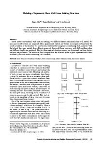
Hümeyra ŞAHİN1, Kürşat Esat ALYAMAÇ2, Ali Sayıl ERDOĞAN3 1,2
Department of Civil Engineering, Fırat University, Turkey
3
Department of Civil Engineering, Bingöl University, Turkey
ABSTRACT Reinforced concrete structural walls are widely used in design of the lateral load resisting systems. Reinforced concrete structural walls allowed to economic and architectural designs in accordance with directions in especially multistory reinforced concrete building systems. Design shear forces are assumed to be proportional to the design base moment in the traditional design of structural walls that are based on forced based methods. However, studies reveal that considerable wall shear forces develop during nonlinear response due to higher mode effects that are not predicted by the force based design methods. This situation can lead to significant errors in the design. In this study, in order to prevent errors, dynamic shear force amplification factor had been studied to obtain by using real seismic accelerations.
In this parametric study, 4,8 and 16 story typical wall buildings were designed for covering strength reduction factors of R=2,4,6,8 and 10 using Mode Superposition Method that forcebased method. Designs were taken into consideration 1st earthquake area and Z3 local site class in Turkish Seismic Design Code (2007). Designed walls were analyzed with nonlinear time history analyses and the dynamic shear force amplification factor () were obtained from the base shear forces were proportioned the design base shear forces. As a result, relations among strength reduction factor (R), first mode period and dynamic shear amplification factor () were determined.
Keywords: Reinforced concrete structural wall, Nonlinear time history analysis, Shear force
INTRODUCTION
Reinforced concrete structural shear walls have long been recognized as effective lateral force resisting systems, capable of conferring good performance to structures subjected to wind and earthquake. Buildings braced by shear walls are invariably stiffer than framed structures, 6 4
2nd International Balkans Conference on Challenges of Civil Engineering, BCCCE, 23-25 May 2013, Epoka University, Tirana, Albania
reducing the possibility of excessive deformations under earthquakes [1]. Their high lateral stiffness can limit or large proportion avoid damage to nonstructural components, and enough strength and detailing can be provided to resist moderate and strong ground shaking with only limited structural damage. As a natural consequence, the use of RC shear walls in buildings is becoming a very popular scheme in the design of multistory buildings to resist lateral loads. The seismic response of shear walls during earthquakes is very complex. In particular, shear walls undergoes severe cracking and localized damage [2]. The nonlinear flexural behavior of concrete shear walls is generally well known. This behavior can be defined in terms of bending moment-rotation or bending moment-curvature response while accounting for axial force-bending moment interaction. In comparison to flexure, the nonlinear shear behavior of concrete shear walls is much less well known, and present nonlinear time history analysis programs use very simple models for shear behavior. The distribution of the lateral forces over the height of the structure specified by building codes for the equivalent lateral force procedure is usually an inverted triangle. These loading shapes are quite adequate for predicting the moment distribution, but usually are far off the mark for the peak shear forces in flexural wall structures. The works of on isolated walls proved that the higher modes of vibration not only increase the elastic shear demand relative to that proportional with the moment demand, but they increase the base shear more significant after the formation of a plastic hinge at the wall base [3]. Consequently, the seismic design strength determined in accordance with code requirements may underestimate the seismic shear and flexural demands in cantilever wall subjected to earthquake loading. Response spectrum analysis, which is a linear dynamic analysis procedure, is commonly used in design to determine the global displacement demands and force demands on individual components of concrete shear walls. While linear dynamic analysis procedures is often used for design purpose, a realistic seismic behavior which accounts for the structural damage can only be captured by performing nonlinear dynamic analysis [4]. Nonlinear dynamic analysis, commonly called nonlinear time history analysis, is the most complete and advanced procedure to estimate the seismic response of structures. Changes in stiffness of members due to material nonlinearity and local damage caused by cracking of concrete and yielding of reinforcement can all be accounted for when performing nonlinear time history analysis. An effective design procedure which can be used to assess the realistic shear demand in RC structural walls is needed. Various empirical approaches have been proposed to estimate the design seismic shear force using a dynamic shear amplification approach where the shear force is first reduced using the force reduction factor due to flexural ductility and then increased again to account for the influence of higher modes on a cantilever wall with a plastic hinge at the base. In this parametric study, 4,8 and 16 story typical wall buildings were designed for covering strength reduction factors of R=2,4,6,8 and 10 using Mode Superposition Method that forcebased method. Designs were taken into consideration 1st earthquake area and Z3 local site class in Turkish Seismic Design Code (2007). Designed walls were analyzed with nonlinear time history analyses and the dynamic shear force amplification factor () were obtained from the base shear forces were proportioned the design base shear forces. As a result, relations 6 5
2nd International Balkans Conference on Challenges of Civil Engineering, BCCCE, 23-25 May 2013, Epoka University, Tirana, Albania
among strength reduction factor (R), first mode period and dynamic shear amplification factor () were determined.
PREVIOUS WORK Dynamic shear amplification of structural wall systems designed to respond nonlinearly during seismic attack has been documented by limited number of researchers in the past. Majority of the researchers had focused on the base shear amplification as the maximum shear forces develop at the base of the wall. Inevitably, research objectives on the subject have been founded on a particular code perspective since the motivation was the code development for inhibiting premature shear failure of structural walls. This seismic shear magnification phenomenon, which was first, documented by Blakeley et al. [5], who pioneered the idea that higher mode effects amplify the base shear with respect to the base shear obtained from conventional code procedures after the formation of a plastic hinge at the base of the wall. Blakely performed non-linear time history analyses on various structural wall models and recommended base shear amplification factors as a function of number of stories (n) of the wall structure. Their work brought about a change in the previsions of the New Zealand seismic code and in turn in several other seismic codes. A possible enlargement of seismic shear demands caused by dynamic effects was also indicated in the response of a full scale 7-storey RC structural Wall tested on a shake table at University of California, San Diego. Studies by Eibl, Keintzel and Seneviratna, Krawinkler [6-7] have shown that base shear amplification is both functions of the first mode period and expected ductility level. Using a similar approach, Ghosh [8] proposed the maximum shear demand at the base of isolated cantilever walls is equal to the sum of the shear force associated with the bending moment capacity of the wall with the resultant force acting at two-thirds the height of the wall (as in the first mode), plus 25% of the inertia force due to the peak ground acceleration acting on the total weight of the building. Eberhard and Sozen [9] proposed a similar expression except the 25% factor ranged from 27 to 30%. The European approach to this problem has changed somewhat throughout the years, as is manifested in the successive drafts of EC8. The present version EN 1998-1 [10] has different amplification formulas depending on the design ductility class (DC). No amplification is specified for wall systems of low ductility class (DC). For uncoupled wall systems with medium ductility (DC-M), i.e., q3.0 a constant 50% increase in shear demand is required. For systems designed for high ductility, i.e., q4.0-6.0 (depending on redundancy) Keintzel’s (1990) formula is specified, namely; = .
.
+ 0.1.
( ) (
)
≤
(1)
6 6
2nd International Balkans Conference on Challenges of Civil Engineering, BCCCE, 23-25 May 2013, Epoka University, Tirana, Albania
in which ε is the base shear amplification factor, q is the strength reduction factor, γRd the overstrength factor, MRd the design flexural strength at the wall base, MEd the design moment at the wall base, TC the upper limit period of the spectral acceleration plateau in the design spectrum and Se(T) is the ordinate of the elastic response spectrum. However, recent research work performed by Rutenberg, Nsieri and Priestley et al.and Fischinger et al. [2,3,11] has shown that the Eurocode procedure needs some modifications in order to provide an improved estimate of shear magnification factors. In particular, the work of Rutenberg and Nsieri has demonstrated that the ε factor is too low for DCM walls, and is also frequently conservative for DCH walls. Seneviratna and Krawinkler and more recently, Rutenberg and Nsieri [12], studied the seismic shear force distribution when flexural hinge forms at the base of a wall. The latter proposed a simple seismic shear envelope that depends on the fundamental period of the structure. The minimum design shear force over the height of the wall is 50% of the maximum at the base. Turkish Seismic Design Code (1997) did not take into account the dynamic base shear amplifications in structural walls at any level of ductility, and the design for shear was based on the shear forces corresponding to the lateral force distribution used for flexural design. Present version of the code (2007) takes the base shear amplification phenomena into account with a constant base shear amplification factor [13]. Dynamic amplification factor is take into account follow paragraph in Turkish Seismic Design Code. In walls satisfying the condition Hw/ℓw> 2.0, design shear force based on the calculation of any considered transverse reinforcement in section, Ve, shall be calculated eg.2 with;
=
(
(2)
)
Dynamic magnification coefficient of shear force placed in this correlation shall be taken as v= 1.5 for frame –wall system and as v= 1.0 for wall system. In the case where a more rigorous analysis is not performed, (Mp)t 1.4 (Mr)t can be taken as the hardening moment capacity in the ground of wall. Recent research works by Kazaz and Celep have suggested modification that amplification factor in Turkish Seismic Design Code.
PARAMETRIC STUDY
In this study, dynamic shear amplification factors and their relation with the first mode period of walls and the strength reduction factors have been investigated through a parametric study based on non-linear time history analyses. Dynamic shear amplification factors are proposed based on regression analyses of the parametric time history analysis results, which are indented to be used in Turkish Seismic Design Code (2007) for shear design of walls.
6 7
2nd International Balkans Conference on Challenges of Civil Engineering, BCCCE, 23-25 May 2013, Epoka University, Tirana, Albania
For investigate, four type shear walls are generated. The generic walls with geometric characteristics given in follow have been analyzed with non-linear time history analyses (Figure 1). In this study, four shear walls models of 4, 8 and 16 stories with different lengths were generated. The stories heights for all models were 3 m. The walls are designed according to the seismic provisions of Turkish Seismic Design Code (2007) for shear design of walls (Figure 1).
Type
The Critical Wall Height
The Wall Height
Transverse Web Reinforcement Ø12/250 Longitudinal Boundary Longitudinal Web Reinforcement10Ø16 Reinforcement Ø16/220
lu=60 cm
lu= 30 cm lw/2= 150 cm
30 cm 25 cm
lu=80 cm
Transverse Web Reinf. Ø12/250 Longitudinal WebReinf. Ø20/210
Lon. Boun. Reinf. 8Ø16
lw/2=200 cm
Transverse Web Reinf. Ø12/250 Longitudinal WebReinf. Ø20/210
30 cm 25 cm
lu=100 cm
lw/2=250
lu=50 cm
TransverseWeb Reinforcement Ø12/ 250 LongitudinalWebReinforcementØ20/ 180
Lon. Boun. Reinf. 6Ø20
lw/2=250
TransverseWeb Reinforcement Ø12/ 250 LongitudinalWebReinforcementØ20/ 180
30cm 25cm
30cm 25cm
Lon. Boun. Reinf. 12Ø20
T4
lu=40 cm
lw/2=200 cm
30 cm 25 cm
Lon. Boun. Reinf. 10Ø20
T3
lw/2= 150 cm
Transverse Web Reinf. Ø12/250 Lon. Boun. Reinf. 6Ø16 Longitudinal Web Reinf. Ø16/170
Transverse Web Reinf. Ø12/250 Longitudinal Web Reinf. Ø16/170
30 cm 25 cm
Lon. Boun. Reinf.12Ø16
T2
Transverse Web Reinf. Ø12/250 Longitudinal Web Reinf. Ø16/220
30 cm 25 cm
30 cm 25 cm
T1
Long. Boundary Reinf. 6Ø14
lu=120cm
lu=60cm
lw/2=300cm
lw/2=300cm
Figure 1. The Generic Walls with Appearance of Cross Sections
Each wall have been consecutively analyzed for the strength levels corresponding to strength reduction factors of R=2, 4, 6, 8 and 10 with 3 strong ground motion acceleration records scaled to fit the Turkish Seismic Design Code (2007) Acceleration Response Spectrum as explained in follow (Figure 2). Designs are taken into consideration 1st earthquake area and Z3 local site class in Turkish Seismic Design Code (2007). For all the walls analyzed, concrete compressive characteristic strength (fc) are taken as 25 MPa and reinforcing steel strength (fy) are taken as 420 MPa. Each wall has been defined as nonlinear shell element in non-linear time history analysis. Mander Model have been used confined and unconfined concrete.
6 8
2nd International Balkans Conference on Challenges of Civil Engineering, BCCCE, 23-25 May 2013, Epoka University, Tirana, Albania
12 10
A (m/s²)
8 6 4 2 0 0.0
0.4
0.8
1.2 1.6 Period (sec)
2.0
2.4
2.8
Figure 2 . Design acceleration response spectrum used in the study Non-linear time history analyses has been executed under four types (hereinafter called T 1, T2, T3 and T4) in order to investigate the sensitivity of the base shear amplification factors to the distribution of plastic hinges along the wall height and the hysteresis characteristics of the plastic hinges. Non-linear time history analyses have been performed by using SAP 2000 v14 (CSI, 2009) structural analysis software.
ANALYSIS
Non-linear time history analyses have been performed for generic wall models of 4,12 and 16 stories with strength levels corresponding to R = 2, 4, 6, 8 and 10. For each generic wall model with the aforesaid strength level, shear forces and maximum story moments have been obtained for each of 3 ground motion record as shown in Figure 3 and Figure 4 for 16 story wall with strength level of R = 6 with comparison to the design moment and shear force diagrams.
16
16
ERZINCAN KOBE MAMMOTH LAKE DESIGN
14 12
12 10 STORY
STORY
10 8
8
6
6
4
4
2
2
0
ERZINCAN KOBE MAMMOTH LAKE DESIGN
14
0
100
200 300 400 STORY SHEAR FORCE (kN)
500
600
0
6 9
0
100
200 300 400 STORY SHEAR FORCE (kN)
500
600
2nd International Balkans Conference on Challenges of Civil Engineering, BCCCE, 23-25 May 2013, Epoka University, Tirana, Albania
T1
T2 16
16 ERZINCAN KOBE MAMMOTH LAKE DESIGN
14 12
12 10 STORY
STORY
10 8
8
6
6
4
4
2
2
0
ERZINCAN KOBE MAMMOTH LAKE DESIGN
14
0
100
200
300 400 STORY SHEAR FORCE (kN)
500
600
0
700
0
100
200
300
400 500 600 700 STORY SHEAR FORCE (kN)
800
900
1000
T3 T4 Figure 3. Mean story shear force diagram of 16 story four type model walls with strength level R=6 16
16 ERZINCAN KOBE MAMMOTH LAKE DESIGN
14 12
12 10 STORY
STORY
10 8
6
4
4
2
2
0
1000
2000
3000 4000 MOMENT (kNm)
5000
6000
0
7000
T1
0
ERZINCAN KOBE MAMMOTH LAKE DESIGN
14 12
4000
6000 MOMENT(kNm)
8000
10000
12000
T2 ERZINCAN KOBE MAMMOTH LAKE DESIGN
14 12 10
STORY
10 8
8
6
6
4
4
2
2
0
2000
16
16
STORY
8
6
0
ERZINCAN KOBE MAMMOTH LAKE DESIGN
14
0
5000
MOMENT (kNm)
10000
15000
0
0
0.5
1
1.5 MOMENT(kNm)
2
2.5 4
x 10
T3 T4 Figure 4. Mean story moment diagram of 16 story four type model walls with strength level R=6
Mean base shear amplification factors derived from type 2 non-linear time history analyses have been collected in a single diagram (βv – T – R diagram) related with the first mode periods of the wall corresponding the section stiffness and strength reduction factors as shown in Figure 5.
7 0
2nd International Balkans Conference on Challenges of Civil Engineering, BCCCE, 23-25 May 2013, Epoka University, Tirana, Albania
DYNAMIC SHEAR AMPLIFICATION FACTOR
5
R2 R4 R6 R8 R10
4.5 4 3.5 3 2.5 2 1.5 1 0.5 0 0.5
1
1.5 2 2.5 SECTION ELASTIC FİRS MODE PERIOD (sec)
3
Figure 5. Dynamic base shear amplification factors obtained from Type 2 time history analyses
CONCLUSIONS Amplified shear forces, particularly at the base of the wall, are probable to cause unexpected premature brittle shear failure modes of diagonal tension, diagonal and sliding before the designed plastic hinge development if the magnified shear forces are not taken into account [16-18]. Practically dynamic shear amplification is taken into account by means of base shear amplification factors applied to the design base shear calculated with the code procedures. These amplification factors are presented principally as a function of first mode period and/or strength reduction factors. 2007 version of the Turkish Seismic Design Code considers the base shear amplification phenomena with a constant base shear amplification factor of 1.5 for frame – wall system and 1.0 for wall system regardless of the first mode period and ductility level of the wall. It is believed that this should be revised with base shear amplification factors as functions of strength reduction factor and first mode period of the wall. It is also believed that a shear force profile along the height of the wall is also necessary in the Turkish Seismic Design Code (2007) not only for preventing shear failures at the base but also along the height of the structural wall. Previous research displayed that, shear forces in yielding walls are not proportional to the design moments and shear force demands are higher than predicted by the code procedures due to higher mode effects after plastic hinge formation at the base of the wall. Parametric study non-linear time history analyses have been performed for code designed generic structural walls, in order to suggest a base shear amplification relationship and a shear force profile for the Turkish Seismic Design Code (2007).
Results of the non-linear time history analysis revealed that dynamic base shear amplification factors increase with increasing first mode period as well as with strength reduction factor. It has shown that the Turkish Seismic Design Code procedure needs some modification in order to provide an improved estimate of shear magnification factor. 7 1
2nd International Balkans Conference on Challenges of Civil Engineering, BCCCE, 23-25 May 2013, Epoka University, Tirana, Albania
It is believed that more information will be available on the real dynamic behavior of yielding structural walls as more full-scale tests and supporting numerical research simulating the complex reinforced concrete behavior are carried out. REFERENCES [1] Avigdor Rutenberg, (2004) “The Seismic Shear Of Ductile Cantilever Wall Systems İn Multistorey Structures” Earthquake Engng Struct. Dyn., Vol. 33, pp 881–896. [2] Paulay, T. and M.J.N. Priestley, (1992), “Seismic Design of Reinforced Concrete and
Masonry Buildings”, John Wiley & Sons, New York, USA. [3] Rutenberg A., E. Nsieri, (2006), “The Seismic Shear Demand in Ductile Cantilever Wall Systems and the EC8 Provisions”, Bulletin of Earthquake Engineering, Vol. 4, Pp. 1-21.
[4] B. R. RAD, (2009), “Seismic Shear Demand In High-Rise Concrete Walls”, Ph. D. Dissertation, the British Columbia University. [5] Blakeley, G., C. Cooney and M. Megget, (1975), “Seismic Shear Loading at Flexural Capacity in Cantilever Wall Structures”, Bulletin of the New Zealand National Society for Earthquake Engineering, Vol. 8, No.4, pp. 278-290. [6] Eibl, J. and E. Keintzel, (1988), “Seismic Shear Forces in RC Cantilever Shear Walls”, Proceedings of Ninth World Conference on Earthquake Engineering, Kyoto, Japan, 2 August-9 August 1991,Vol. VI, pp. VI/5-VI/10. [7] Senaviratna, K. and H. Krawinkler, (1994), “Strength and Displacement Demands for Seismic Design of Structural Walls”, Proceedings of Fifth U.S. National Conference on Earthquake Engineering, Chicago, Illinois, Vol. II, pp.181- 190. [8] Gosh, S. and P. Markevicius, (1990), “Design of Earthquake Resistant Shearwalls to Prevent Shear Walls”, Proceedings of Fourth U.S. National Conference on Earthquake Engineering, Palm Springs, California, 20 May-24 May 1990, Vol. 2, pp. 905-913. [9] Eberhard, M. and M. Sözen, (1993), “Behavior Based Method to Determine Design Shear in Earthquake-Resistant Walls”, Journal of the Structural Division, American Society of Civil Engineers (ASCE), Vol. 119(2), pp. 619-640. [10] CEN, 2004, Eurocode EC8, “Eurocode (EC) 8 Design of Structures for Earthquake Resistance-Part I General Rules, Seismic Actions and Rules For Buildings (EN 1998-1)”, Comité Européen de Normalisation, Brussels. [11] Rejec K., Isakovi´c T., Fischinger M., “Seismic Shear Force Magnification İn Rc Cantilever Structural Walls, Designed According To Eurocode 8”, Bull Earthquake Eng. DOI 10.1007/s10518-011-9294-y. [12] Rutenberg, A., (2004) ,“The seismic shear of ductile cantilever wall systems in multistorey structures”, Earthquake Engineering & Structural Dynamics 33, 881–896. [13] Turkish Seismic Design Code, (2007), “Specification for Buildings to be Built on Seismic Areas”, in Turkish, Ministry of Public Works and Settlement, Ankara, Turkey. 7 2
2nd International Balkans Conference on Challenges of Civil Engineering, BCCCE, 23-25 May 2013, Epoka University, Tirana, Albania
[14] Kazaz I., (2010),”Dynamic Characteristics and Performance Assessment of Reinforced Concrete Structural Walls”, Ph. D. Dissertation, the Middle East Technical University, Turkey. [15] Celep U. U., (2008), “Dynamic Shear Amplification In Seismic Response Of Structural Wall Systems”, Ph. D. Dissertation, The Boğaziçi University, Turkey. [16] Mesa A.D.A., (2002)“Dynamic Amplification Of Seismic Moments And Shear Forces In Cantilever Walls” Ms. Dissertation, The University of Studi Superiori di Pavia. [17] B.R. Rad and P. Adebar, (2008) “Dynamic Shear Amplification In High-Rise Concrete Walls: Effect Of Multiple Flexural Hinges And Shear Cracking” The 14 th World Conference on Earthquake Engineering, Beijing, China. [18] CSI, 2009, “SAP 2000, Static and Dynamic Finite Element of Structures”, Computers and Structures Inc., Berkeley, California, USA.
7 3