OPTICAL DESIGN of OPHTHALMIC LENSES Introduction We tend to prescribe ophthalmic lenses as though any lens with the right back vertex power will do. Lens curves are not, however, chosen haphazardly. Just like a telescope, photographic objective, or any other optical device, ophthalmic lenses are designed to maximize performance.
General Principles of Optical Design
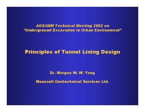
set up first system
evaluate the system's performance
yes is it good enough?
end
no change system
The process of optical design follows the flow chart above.
ophthalmic lens design, page 1
© W. F. Long, 1992
Here are the parameters a lens designer may vary to improve performance:
☞ ☞ ☞ ☞
surface curvatures optical indices number of elements spacing of elements.
These are the "degrees of freedom". In addition to degrees of freedom there are constraints, for example,
☞ ☞ ☞
focal lengths magnification physical constraints like weight, lens to screen distance, etc.
Here are the tools of the optical designer:
☞ ☞ ☞ ☞ ☞ ☞
ray tracing knowledge of aberrations computation short cuts such as Seidel 3rd order formulas, the Abbe sine condition, Petzval sum image evaluation including intercepts with the optic axis from meridional ray plots, and spot diagrams showing the intersection of rays with the image plane, modulation transfer function automatic improvement computer programs. A typical algorith minimizes a "figure of merit", a function depending on a few traced rays.
A key step in lens design is trigonometric ray tracing. Traces were carried out with logarithms until 1925, desk calculators until 1950, and computers since then. At present microcomputers can solve most problems in real time.
ophthalmic lens design, page 2
© W. F. Long, 1992
Spectacle Lens Design The goal of the spectacle lens designer is to give the patient clear vision at all distances through any portion of the spectacle lens. He has a very limited number of degrees of freedom. Practical conditions specify lens materials, safety considerations fix lens thickness, fashion dictates lens position before the face, weight and cosmesis mean only two lens surfaces may be used. With so few degrees of freedom, few aberrations may be corrected. Fortunately, few are needed. The wide angle aberrations, spherical aberration and coma are of no importance since the entrance pupil of the eye is so small. The visual system adapts quickly to distortion, so distortion may be neglected. Likewise, the eye already has chromatic aberration and the additional aberration of spectacle materials may be ignored. The spectacle lens designer is left only with the job of correcting to within tolerable limits astigmatism and curvature of field so as to produce maximum dynamic field of view for the patient.
ophthalmic lens design, page 3
© W. F. Long, 1992
Layout of the Spectacle Design Problem As the eye rotates about its center of rotation, C, the image will be in focus for the ametropic eye if it is in focus on the far point sphere of the eye. The far point sphere is a sphere with its center at C, and the far point of the ametropic eye on its surface.
far point sphere
C •
Z
center of rotation
The diagram shows the far point sphere for a myope. If the image is not in sharp focus on the far point sphere, it may be good enough if the line foci from the lens (line foci because of marginal astigmatism) lie close to the far point sphere or bracket it. Design calculations are done by tracing rays trigonometrically through the lens and calculating the positions of the two line foci according to formulas which are not too difficult to derive. (We won't derive them, however.) Ideally, the two line foci coincide on the far point sphere. If, as usual, they don't, other criteria may be used, i.e. the line foci coinciding with each other somewhere off the far point sphere, line foci bracketing the far point sphere and being close to each other, etc. If a criterion is not satisfied for a given base curve, a new one is tried, etc. Incidentally, the layout above shows why patients with high prescriptions may notice some blurring if the optical center of the spectacle lens is below their eye's optical axis. ophthalmic lens design, page 4
© W. F. Long, 1992
Third Order Theory In third order optical theory we use the expansions of the sine and cosine up through third order instead of to first order as in paraxial optics. These expansions are sin θ = θ - θ 3 /3! cos θ =1- θ 2 /2! By using these third order approximations, we can solve analytically for the base curve F 2 as a function of the back vertex power of the lens, F V ', n the index of the lens, and z , the distance from the back vertex of the lens to the center of rotation of the eye, assuming the lens is a thin lens. The results are valid if the eye rotates no more than 15° from the primary line of sight. The result is an equation of the form
aF 2 2 + bF 2 + c =0 where a , b , and c depend on lens power F , n , and z. Ostwalt and Wollaston Solutions If our design criterion is that the two line foci coincide, though not necessarily on the far point sphere, astigmatism is wholly compensated though a sphere error remains. In 3rd order this leads to the equation above where
a = n +2 b =2 n 2 -1)/ z -( n +2) F c = nF 2 -2( n -1) F / z + n ( n -1) 2 / z If this is plotted as F 2 vs. F , we get the famous Tscherning ellipses. The graph below shows the Tscherning ellipse for a working distance 33cm with z =25mm. The ellipse is plotted for remote objects. The upper division is labelled the Ostwalt branch and the lower the Wollaston branch, after their designers. The Wollaston branch lenses have ophthalmic lens design, page 5
© W. F. Long, 1992
the advantage of having the same form at distance and near, but the curves are steep and hard to make as well as uncosmetic The Ostwalt branches are more practical, but ideally require about a three diopter flatter base curve when used for near objects
back surface power (D)
point focal design, DV 0
-10
Ostwalt Branch
-20
Wollaston Branch
-30 -30
-20
-10
0
10
lens power (D) Percival Solution In Percival's design philosophy, we allow astigmatism but require the mean error to be correct, that is the far point foci straddle the far point sphere. In third order theory this gives
a =3 b =4( n -1)/ z -( n +2) F c = nF 2 -2( n -1) F / z +( n -1) 2 / z 2 These parameters lead to ellipses similar to the point-focal philosophy lens ellipses. Design for near and distant viewing distances is essentially identical. The Percival philosophy is similar to that used in modern spectacle lens design. ophthalmic lens design, page 6
© W. F. Long, 1992
Percival design, DV back surface power (D)
0
-10
Ostwalt Branch
-20
-30 -30
Wollaston Branch
-20
-10
0
10
20
lens power (D) Design of Sphero-Cylinder Lenses Sphero-cyl lenses have two far point spheres and appropriate line foci must approximate each sphere. Line foci are a combination of radial and non-radial astigmatism. Ray tracing becomes much more difficult. Modern Corrected Curve Lens Series Modern corrected curve lens series are calculated using trigonometric ray tracing so as to consider angles of rotation of -30° about the line of sight. Slightly different philosophies have been employed. Most use a Percival type philosophy to minimize importance of astigmatism. Punktal (Zeiss). Rotation of 35° for F >0, 30° for F