IETE 46th Mid Term Symposium “Impact of Technology on Skill Development” MTS MTS- 2015 Special Issue of International Journal of Electronics, Communication & Soft Computing Science and Engineering, ISSN: 2277 2277-9477
Implementation of High Power Microwave Technology in Military Applications Madhur S. Kurhekar
Mamik S. Gade
methods, such as powerful batteries, can also be used to create a reusable HPM weapon. HPM energy can be focused using a specially shaped antenna, or emitter. Unlike HEMP, however, HPM radiation is comprised of shorter wave forms at higher higher-frequencies, which make it highly effective against electronic equipment and more difficult to fight against. Also, HPM energy at higher power levels (megawatts), and powered for a longer time interval, reportedly could cause physical harm to persons near the source emitter.
Abstract—High High Power Electromagnetic Pulse generation techniques and High Power Microwave technology have led to the development of the concept of E-bombs bombs (Electromagnetic bombs) which are becoming technically feasible, with new applications in both Strategic and Tactical actical Information Warfare. The development of conventional E-bomb bomb devices allows their use in non-nuclear nuclear confrontations. This paper discusses aspects of the technology base, weapon delivery techniques and proposes a foundation for the use of such devices in military applications. Index Terms—Introduction, Introduction, Description of High-Power Microwave (HPM),, Maximising Electromagnetic Bomb Lethality, Defence against Electromagnetic Bombs, Conclusion, References.
III.
IV. TECHNOLOGY BASE FOR CONVENTIONAL ELECTROMAGNETIC BOMBS The technology base which may be applied to the design of electromagnetic bombs is both diverse, and in many areas quite mature. Key technologies which are extant in the area are explosively pumped Flux Compression Generators (FCG), explosive or propellant driven Magneto MagnetoHydrodynamic (MHD) generators and a range of HPM devices, the foremost of which is the Virtual Cathode Oscillator or Vircator.
DESCRIPTION OF HIGH-P POWER MICROWAVE (HPM (HPM)
HPM is a non-nuclear nuclear radio frequency energy field. It can be produced as a weapon when a powerful chemical detonation is instantly transformed by a special coil device, called a flux compression generator, into a strong electromagnetic field of microwave energy. 8 Other
4.1 Explosively Pumped Flux Compression Generators The FCG[1] is a device capable of producing electrical energies of tens of MegaJoules in tens to hundreds of microseconds of time, in a relatively compact package. With
17 Journal Impact Factor-2.02 Indexed by- ProQuest, DOAJ and many International Bodies Bodies.
DISRUPTIVE CAPABILITIES OF HEMP AND HPM WEAPONS
A high altitude nuclear explosion produces two major energy components that arrive in sequence, and which have measurably different effects that can be cumulatively damaging to electronic nic equipment. The first energy component is the initial energy shockwave which lasts about one microsecond, and is similar to extremely intense static electricity that can overload circuitry for every electronic device that is within line of sight of the burst. A secondary energy component then arrives, which has characteristics that are similar to a lightning strike. By itself, this second energy component might not be an issue for some critical infrastructure equipment, if anti anti-lightning protective measures are already in place.
I. INTRODUCTION Dependency upon a resource or infrastructure base produces vulnerability. Modern industrialized nations are now heavily dependent upon their fundamental computing and communications infrastructure. Virtually all computing and communications technology which comprises the technological foundation of this infrastructure shares a common attribute, in that it is built with modern high density semiconductor components. This dependency upon the modern semiconductor device produces a global vulnerability to attack by weapons which are specifically specific designed to damage or destroy semiconductor components. Importantly, such weapons are now both technically feasible and relatively economical to build, in comparison with established weapons of mass destruction such as the nuclear bomb. These devices are electromagnetic weapons, and the foremost of these is the E-bomb, bomb, which can produce an e-m e field of such intensity, targeted item/items of electronic equipment experiences either a soft/hard kill. II.
Aishwarya D. Joshi.
IETE 46th Mid Term Symposium “Impact of Technology on Skill Development” MTS MTS- 2015 Special Issue of International Journal of Electronics, Communication & Soft Computing Science and Engineering, ISSN: 2277 2277-9477
peak power levels of the order of TeraWatts to tens of TeraWatts,, FCGs may be used directly, or as one shot pulse power supplies for microwave tubes. The current produced by a large FCG is between ten to a thousand times greater than that produced by a typical lightning stroke.[2] The central idea behind the construction on of FCGs is that of using a fast explosive to rapidly compress a magnetic field, transferring much energy from the explosive into the magnetic field. The initial magnetic field in the FCG prior to explosive initiation is produced by a start current. In a typical helical FCG, a cylindrical copper tube forms the armature. This tube is filled with a fast high energy explosive. The armature is surrounded by a helical coil of heavy wire, typically copper, which forms the FCG stator. The stator winding is in some me designs split into segments, with wires bifurcating at the boundaries of the segments, to optimize the electromagnetic inductance of the armature coil. The intense magnetic forces produced during the operation of the FCG could potentially cause the device ce to disintegrate prematurely if not dealt with. This is typically accomplished by the addition of a structural jacket of a non non-magnetic material. Materials such as concrete or Fibre Fibre-glass in an Epoxy matrix have been used. It is typical that the explosiv explosive is initiated when the start current peaks. This is usually accomplished with a explosive lens plane wave generator which produces a uniform plane wave burn (or detonation) front in the explosive. Once initiated, the front propagates through the explosive explosiv in the armature, distorting it into a conical shape (typically 12 to 14 degrees of arc). Where the armature has expanded to the full diameter of the stator, it forms a short circuit between the ends of the stator coil, shorting and thus isolating the start rt current source and trapping the current within the device. The principal technical issues in adapting the FCG to weapons applications lie in packaging, the supply of start current, and matching the device to the intended load.
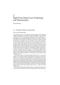
The Vircator Whilst FCGs are potent technology base for the generation of large electrical power pulses, the output of the FCG is by its basic physics constrained to the frequency band below ow 1 MHz Many target sets will be difficult to attack even with very high power levels at such frequencies, moreover focusing the energy output from such a device will be problematic. A HPM device overcomes both of the problems, as its output power may be tightly focused and it has a much better ability to couple energy into many target types. A wide range of HPM devices exist. Relativistic Klystrons, Magnetrons, Slow Wave Devices, Reflex triodes and Vircators are all examples of the available technology base,[3,4] out of which Vircators are widely used. This is because the Vircator is a one shot device capable of producing a very powerful single pulse of radiation, yet it is mechanically simple, small and robust, and can operate over a relatively broad band d of microwave frequencies. The fundamental idea behind the Vircator is that of accelerating a high current electron beam against a mesh (or foil) anode. Many electrons will pass through the anode, forming a bubble of space charge behind the anode. Under the proper conditions, this space charge region will oscillate at microwave frequencies. If the space charge region is placed into a resonant cavity which is appropriately tuned, very high peak powers may be achieved. Conventional microwave engineering techniques hniques may then be used to extract microwave power from the resonant cavity. Because the frequency of oscillation is dependent upon the electron beam parameters, Vircators may be tuned in frequency, where the microwave cavity will support appropriate modes. mode Power levels achieved in Vircator experiments range from 170 kiloWatts to 40 GigaWatts over frequencies spanning the decimetric and centimetric bands.[5]
Fig.4.2.1 :Axial Virtual Cathode Oscillator
Fig.4.1:Explosively Generators
Pumped
Flux
The two most commonly described configurations for the Vircator are the Axial Vircator (AV) and the Transverse Vircator (TV). The Axial Vircator is the simplest by design, and has generally produced the best power output in experiments. It is typically built into a cylindrical waveguide structure. Power is most often extracted by transitioning the waveguide into a conical horn structure, which functions as an antenna. AVs typically oscillate in Transverse Magnetic (TM) modes. The Transverse Vircator injects cathode
Compression
4.2 High Power Microwave Sources
18 Journal Impact Factor-2.02 Indexed by- ProQuest, DOAJ and many International Bodies. Bodies
IETE 46th Mid Term Symposium “Impact of Technology on Skill Development” MTS MTS- 2015 Special Issue of International Journal of Electronics, Communication & Soft Computing Science and Engineering, ISSN: 2277 2277-9477
current from the side of the cavity and wi will typically oscillate in a Transverse Electric (TE) mode.
V.
to the much higher impedance of the antenna, and an ensure that the current pulse does not vaporise the cable prematurely.
MAXIMIZING ELECTROMAGNETIC BOMB LETHALITY
Fig 5.3: Example Of Vircator/Antenna Assembly Microwave bombs have a broader range of coupling modes and given the small wavelength in comparison with bomb dimensions, can be readily focussed against targets with a compact antenna assembly. Assuming that the antenna provides the required weapon footprint, there are at least two mechanisms which can be employed to further maximise lethality. The first is sweeping the frequency or o chirping the Vircator. This can improve coupling efficiency in comparison with a single frequency weapon, by enabling the radiation to couple into apertures and resonances over a range of frequencies. The second mechanism which can be exploited to improv improve coupling is the polarisation of the weapon's emission. If we assume that the orientations of possible coupling apertures and resonances in the target set are random in relation to the weapon's antenna orientation, a linearly polarised emission will only exploit half of the opportunities available.A circularly polarised emission will exploit all coupling opportunities. The practical constraint is that it may be difficult to produce an efficient high power circularly polarised antenna design which is compactt and performs over a wide band. Some work therefore needs to be done on tapered helix or conical spiral type antennas capable of handling high power levels, and a suitable interface to a Vircator with multiple extraction ports must devised. A possible implementation imp is depicted in Fig.. In this arrangement, power is coupled from the tube by stubs which directly feed a multi-filar multi conical helix antenna. An implementation of this scheme would need to address the specific requirements of bandwidth, beamwidth, efficiency of coupling from the tube, while delivering circularly polarised radiation. Another aspect of electromagnetic bomb lethality is its detonation altitude, and by varying the detonation altitude, a trade-off off may be achieved between the size of th the lethal footprint and the intensity of the electromagnetic field in that footprint.
Fig.5.1: e-Bomb Lethal Radius The first step in maximizing bomb lethality is to maximize the peak power and duration of the radiation of the weapon. Forr a given bomb size, this is accomplished by using the most powerful flux compression generator (and Vircator in a HPM bomb) which will fit the weapon size, and by maximizing the efficiency of internal power transfers in the weapon. Energy which is not emitted tted is energy wasted at the expense of lethality. The second step is to maximise the coupling efficiency into the target set. A good strategy for dealing with a complex and diverse target set is to exploit every coupling opportunity available within the bandwidth of the weapon.
Fig.5.2: Low Frequency E-Bomb Bomb Warhead A low frequency bomb built around an FCG will require a large antenna to provide good coupling of power from the weapon into the surrounding environment. Whilst weapons built this way are inherently herently wide band, as most of the power produced lies in the frequency band below 1 MHz compact antennas are not an option. One possible scheme is for a bomb approaching its programmed firing altitude to deploy five linear antenna elements. These are prod produced by firing off cable spools which unwind several hundred metres of cable. Four radial antenna elements form a "virtual" earth plane around the bomb, while an axial antenna element is used to radiate the power from the FCG. The choice of element lengths would need to be carefully matched to the frequency characteristics of the weapon, to produce the desired field strength. A high power coupling pulse transformer is used to match the low impedance FCG output
19 Journal Impact Factor-2.02 Indexed by- ProQuest, DOAJ and many International Bodies. Bodies
IETE 46th Mid Term Symposium “Impact of Technology on Skill Development” MTS MTS- 2015 Special Issue of International Journal of Electronics, Communication & Soft Computing Science and Engineering, ISSN: 2277 2277-9477
VI.
An electromagnetic bomb delivered by a conventional aircraft can offer a much better ratio of electromagnetic device mass to total bomb mass, as most of the bomb mass can be dedicated to the electromagnetic lectromagnetic device installation itself. It follows therefore, that for a given technology an electromagnetic bomb of identical mass to a electromagnetic warhead equipped missile can have a much greater lethality, assuming equal accuracy of delivery and technologically similar electromagnetic device design. An electromagnetic bomb warhead will comprise an electromagnetic device, an electrical energy converter and a energy storage device to pump and sustain the electromagnetic device charge after separation separatio from the delivery platform.
TARGETING ELECTROMAGNETIC BOMBS
The task of identifying targets for attack with electromagnetic bombs can be complex. Certain categories of target will be very easy to identify entify and engage. The radar sites and communications nodes are all targets which can be readily identified through conventional photographic, satellite, imaging radar, electronic reconnaissance and humint operations. These targets are typically geographically ally fixed and thus may be attacked providing that the aircraft can penetrate to weapon release range. With the accuracy inherent in GPS/inertially guided weapons, the electromagnetic bomb can be programmed to detonate at the optimal position to inflict a maximum of electrical damage.
Fig.7.1: The Delivery of Conventional Electromagnetic Bombs The USAF has recently deployed the Northrop GAM (GPS Aided Munition) on the B-22 bomber [7], and will by the end of the decade deploy the GPS/inertially guided GBU GBU-29/30 JDAM (Joint Direct Attack Munition) and the AGM AGM-154 JSOW (Joint Stand Off Weapon)glidebomb. A major advantage of using electromagnetic bombs is that they may be delivered by any tactical aircraft with a nave nave-attack system capable of delivering GPS guided gu munitions. As we can expect GPS guided munitions to be become the standard weapon in use by Western air forces by the end of this decade, every aircraft capable of delivering a standard guided monition also becomes a potential delivery vehicle for a electromagnetic lectromagnetic bomb. Should weapon ballistic properties be identical to the standard weapon, no software changes to the aircraft would be required.
Fig.6.1: Lathel Footprint Of HPM E Bomb In Relation To Altitude Mobile and camouflaged targets which radiate overtly can also be readily engaged. Mobile and relocatable air defence equipment, mobile communications nodes andd naval vessels are all good examples of this category of target. While radiating, their positions can be precisely tracked with suitable Electronic Support Measures (ESM) and Emitter Locating Systems (ELS) carried either by the launch platform or a remote surveillance platform. In the latter instance target coordinates can be continuously data linked to the launch platform. As most such targets move relatively slowly, they are unlikely to escape the footprint of the electromagnetic bomb during the weapon's flight time. Mobile or hidden targets which do not overtly radiate may present a problem, particularly should conventional means of targeting be employed. This solution is the detection and tracking of Unintentional Emission (UE).[6]
VII.
VIII. DEFENCE AGAINST ELECTROMAGNETIC BOMBS
THE DELIVERY OF CONVENTIONAL ELECTROMAGNETIC BOMBS
The most effective defence against electromagnetic bombs is to prevent ent their delivery by destroying the launch platform or delivery vehicle, as is the case with nuclear weapons. This however may not always be possible, and therefore systems which can be expected to suffer exposure to the electromagnetic weapons effects m must be electromagnetically hardened. The most effective method is
As with explosive warheads, electromagnetic warheads will occupy a volume of physical space and will also have some given mass (weight) determined by the density of the internal hardware. Like explosive warheads, electrom electromagnetic warheads may be fitted to a range of delivery vehicles.
20 Journal Impact Factor-2.02 Indexed by- ProQuest, DOAJ and many International Bodies. Bodies
IETE 46th Mid Term Symposium “Impact of Technology on Skill Development” MTS MTS- 2015 Special Issue of International Journal of Electronics, Communication & Soft Computing Science and Engineering, ISSN: 2277 2277-9477
to wholly contain the equipment in an electrically conductive enclosure, termed a Faraday cage, which prevents the electromagnetic field from gaining access to the protected equipment.
IX. •
•
•
•
REFERENCES [1] C. M. Fowler, W. B. Garn, and R. S. Caird, Production of Very High Magnetic Fields by Implosion, Journal of Applied Physics, Vol. 31, No. 3, 588-594, March, 1960. [2] The EMP - A Triangular Impulse, 2.29, A Handbook Series on Electromagnetic Interference ce and Compatibility, Don White Consultants, Maryland, 1978. [3] Granatstein V.L., Alexeff I., High Power Microwave Sources, Artech House, Boston, London, 1987 [4] Heoberling R.F., Fazio M.V., Advances in Virtual Cathode Microwave Sources, IEEE Transactionss on Electromagnetic Compatibility, Vol. 34, No. 3, 252, August 1992. [5] Thode L.E., Virtual-Cathode Cathode Microwave Device Research: Experiment and Simulation, Chap- ter 14 in High Power Microwave Sources, 1987. [6] Herskowitz D., The Other SIGINT/ELINT, Journal of Electronic Defence, April, 1996. [7] B-2 2 Precision Weapons, unclassi unclassified briefing, NorthropGrumman Corporation, September, 1995, unpublished material. [8] RAAF, DI(AF) AAP1003, Ch.8 The Law of Aerial Targeting, Ta Operations Law for RAAF Com- manders, First Edition, RAAF APSC, Canberra, 1994. [9] Reinovsky R.E., Levi P.S. and Welby J.M., An Economical, 2 Stage Flux Compression Generator System, Digest of Technical Papers, 5th IEEE Pulsed Power Conference, pp.216, p.216, IEEE, New York, 1985. [10] Szafranski R., Col USAF, Parallel War and Hyperwar, Chapter 5 in Schneider B.R, Grinter L.E., Battlefield field of the Future, 21st Century Warfare Issues, Air University Press, Maxwell AFB, September 1995. [11] van Eck W., "Electromagnetic tromagnetic Radiation from Video Display Units: An Eavesdropping Risk", Computers and Security, 1985, pp. 269 [12] EW Systems: AN/ Designated Hardware, pp.86, International Countermeasures Handbook, 10th Edition, Cardiff Publishing, Colorado, 1985 [13] Fanthome thome B.A., MHD Pulsed Power Generation, Digest of Technical Papers, 7th IEEE Pulsed Power Conference, pp.483, IEEE, New York, 1989 Goforth J.H. et al, Experiments with Explosively Formed Fuse [14] Opening Switches in Higher Efficiency ficiency Circuits, Digest of Technical T Papers, 7th IEEE Pulsed Power Conference, pp.479, IEEE, New York, 198
LIMITATIONS OF ELECTROMAGNETIC BOMBS
The limitations of electromagnetic weapons are determined by weapon implementation and means of delivery. Weapon implementation can affect the electromagnetic field strength achievable at a given radius. The choice of means m of delivery will affect the accuracy with which the weapon can be positioned in relation to the intended target. In the context of targeting military equipment, it must be noted that thermionic technology (i.e. vacuum tube equipment) is substantiallyy more resilient to the electromagnetic weapons effects than solid state (i.e. transistor) technology. Therefore a weapon optimised to destroy solid state computers and receivers may cause little or no damage to a thermionic technology device. Therefore a hard electrical kill may not be achieved against such targets unless a suitable weapon is used. Radiating targets such as radars or communications equipment may continue to radiate after an attack even though their receivers and data processing systems hhave been damaged or destroyed. This means that equipment which has been successfully attacked may still appear to operate. Where collateral electrical damage is a consideration, accuracy of delivery and lethal radius are key parameters. An inaccurately delivered weapon of large lethal radius may be unusable against a target should the likely collateral electrical damage be beyond acceptable limits. This can be a major issue for users constrained by treaty provisions on collateral damage.[8]
CONCLUSION Electromagnetic ectromagnetic bombs are Weapons of Electrical Mass Destruction with applications across a broad spectrum of targets, spanning both the strategic and tactical. As such their use offers a very high payoff in attacking the fundamental information processing and nd communication facilities of a target system. The massed application of these weapons will produce substantial paralysis in any target system. However, HPM energy at higher power levels (megawatts), and powered for a longer time interval, reportedly couldd cause physical harm to persons near the source.
21 Journal Impact Factor-2.02 Indexed by- ProQuest, DOAJ and many International Bodies. Bodies