Impedance Cardiography Client: Professor Webster Advisor: Mr. Amit Nimunkar
Leader: Jacob Meyer Communicator: David Schreier BSAC: Tian Zhao BWIG: Ross Comer
I.
Problem Statement Current methods for measuring cardiac output are invasive. Impedance Cardiography is a
non-invasive medical procedure utilized in order to properly analyze and depict the flow of blood through the body. With this technique, four electrodes are attached to the body—two on the neck and two on the chest—which take beat by beat measurements of blood volume and velocity changes in the aorta. However, our client hypothesizes that the current method withholds degrees of inaccuracy due to the mere fact that the electrodes are placed too far from the heart. The goal of this project is to design an accurate, reusable, spatially specific system that ensures more accurate and reliable cardiographic readings. Furthermore, this system must produce consistent results able to be accurately interpreted by industry professionals. More specifically, this semester our precise goal is to begin experimental impedance testing on human subjects using an electrode array, placing electrodes directly over the aorta, and using a custom circuit to filter out our signal.
II.
Background It is frequently necessary in the hospital setting to assess the state of a patient’s circulation.
Here the determination of simple measurements, such as heart rate and blood pressure, may be adequate for most patients, but if there is a cardiovascular condition such as sepsis or cardiomyopathy then a more detailed approach is needed. In order to non-invasively gather specific measurements on the volume of blood pumped by the heart (cardiac output) through the aorta, the technique of impedance cardiography can be used [3]. Impedance cardiography is used to measure the change in resistance of the aorta has blood passes through [2]. These changes in resistance can then be used in specific equations to calculate the pressure and flow blood out of the heart, this in turn can then be used to calculate cardiac output [1]. These measurements are useful both in establishing a patient’s initial cardiovascular state and in measuring one’s response to various
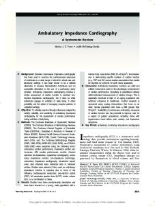
therapeutic interventions such as transfusion, infusion of inotropic drugs, and infusion of vasoactive drugs [4]. Existing methods of measuring cardiac output accurately are very invasive and because of this, these procedures are rarely used, despite the critical information that that could be used. If carefully carried out, the Fick method is accurate but requires a pulmonary artery catheter that is not practical in routine clinical practice. Several variants of this method have been devised, and the accuracy of invasive measures is unmatched thus far in impedance cardiography [4]. Transoesophageal echocardiography (TOE) provides diagnosis and monitoring of a variety of structural and functional abnormalities of the heart [3]. This process can be used to derive cardiac output from measurement of blood flow velocity by recording the Doppler shift of ultrasound waves reflected from the red blood cells [3]. The main disadvantage of this method is that a skilled operator is required to perform surgery. The probe is large and precision is required, as well as anesthesia on the patient which drives up the cost of the operation. The equipment is very expensive, and the probe cannot be fixed to give continuous pressure and flow readings without an expert surgeon. A non-invasive option that could potentially save money for the patient and increase ease of measuring cardiac output is impedance cardiography. First described by Nyoer in 1940, the conventional impedance cardiogram is a record of variations of chest impedance (resistance to current flow), obtained by using an electric current passed from the neck to the upper abdomen as seen in Figure 1 [1]. This high frequency, non-stimulating current is not only noninvasive, but painless to the Figure 1: Current Impedance Cardiography electrode placement.
patient as well. The frequency of the current (about 150 kHz) passing through the chest and heart is high enough to prevent sensation or muscle stimulation but low enough so that the pattern of current flow is similar to that of direct current [1]. Traditionally, chest impedance is recorded between the thoracic inlet at the base of the neck and the thoracic outlet at the level of the diaphragm [4]. The impedance signal is related to changes in the size and composition of bloodcontaining structures within the chest, and it is by this reasoning the impedance cardiogram promises to reveal meaningful information concerning cardiac output and the effectiveness of the heart as a pump on a beat-by-beat basis [4]. This would be extremely useful for monitoring critically ill patients and patients undergoing anesthesia, especially in cases where blood volume or cardiac output may change significantly. Although indices derived from the chest impedance signal track cardiac stroke volume very well, the absolute values of stroke volume of blood per heartbeat are considered unreliable in most clinical settings [4]. This is especially the case in a situation involving congestive heart failure when the ventricular ejection fraction is greatly diminished, or in patients with either reduced or increased peripheral vascular resistance [4]. In addition, comparisons of impedance based stroke volume and cardiac output with results from the green dye dilution or the Fick methods show that the impedance cardiogram tends to overestimate stroke volume by 5 to 10 percent, with rather wide standard deviations, leading to the conclusion that the impedance cardiography method is not accurate [3]. Recent studies have emphasized that changes in the impedance of lungs, great vessels, cardiac atria, and cardiac ventricles during the cardiac cycle are complex and countervailing, leading to a small net signal of uncertain origin [4]. In sick patients with varying pathophysiology, such as reduced ventricular ejection fraction or reduced peripheral vascular, the factors that combine to give reasonable predictions in more healthy individuals may fail. Accordingly, interpretations of the data
from impedance cardiography have tended to be tentative and guarded, and acceptance of the technique is not widespread and has not been able to replace traditional invasive methods. Despite these limitations, taking a new perspective on electrode arrangement that would force current through the cardiac ventricles [5]. By placing the electrodes directly over the heart instead of the neck and abdomen, it is proposed by Professor John Webster that we can attain a more accurate signal. Anatomic and physiologic modeling of this approach lead to several surprising results, and indicate that impedance based methods can provide accurate, painless, and noninvasive cardiac monitoring of cardiac output continuously during the entire cardiac cycle [5]. The goal of this project is to design an accurate, reusable, spatially specific system that ensures more accurate and reliable cardiographic readings. Furthermore, this system must produce consistent results able to be accurately interpreted by industry professionals. More specifically, our primary goal is to ensure the device must not only collect an impedance signal, it must also isolate the signal in its output using a variety of filters, including a phase sensitive demodulator. During the previous semester the impedance cardiography group was able to develop a spatially specific electrode array for use in testing of the proposed new electrode positions by professor Webster. While the group was able to attain some promising data of relative changes in resistance per heart beat in the aorta, the ECG signal was a huge interference on top of the changing resistance, along with noise associated with a the 60 Hz frequency have all electrical devices plugged into standard wall outlets. In order to fix this problem, this semester our new impedance cardiography group is designing two filters, a passive filter system and possibly a phase sensitive demodulator designed by Peter Klomberg and Tian Zhou. The final prototype will be used for research purposes in improving the cardiography technique and will eventually be used in a medical setting. We hope to use this new circuit and a new electrode array design to test human subjects this semester, barring our proposal for human testing to the IRB is accepted.
III.
Client Specifications In June of 2010 we submitted a proposal to the IRB for human testing. Our main goal is to
use a custom circuit and a specifically designed electrode array to test equal numbers of males and females to investigate the concept of impedance cardiography more thoroughly. Professor Webster would like us to design a spatially specific electrode array that can be adjustable in order to fit numerous varieties of electrode positions to determine optimal location. A new goal that we will be focusing on with respect to the electrode array is to format a new design so that we can fit females. Another crucial goal for this semester is to build a circuit that integrates a phase sensitive demodulator in order to better filter our signal so that we can read the pressure wave from the heart without the interference of the ECG signal or the noise associated with any electrical device. Ultimately we will correlate the new demodulator circuit as well as the new electrode array to test human subjects once approval for our request to the IRB is accepted.
IV. Circuit In our previous semester we built a standard ECG circuit that was presented in Professor Webster’s bioinstrumentation 310 class. This circuit worked decently well for us initially, allowing us to see a distinct pressure wave on our 150 kHz carrying frequency. This simple circuit fell short because of the extensive interference from the lab around us and from the ECG signal of the heart. We attempted to filter out the interference with a simple set up of a diode to rectify the signal and subsequent high and low pass filters. The circuit actually became our main limiting factor to progress on the project because of the interference, so this is a main focus this semester. With the extensive help of Peter Klomberg, Tian was able to draw a new circuit that incorporates three op amps and an analog switch that will act as our phase sensitive demodulator. The purpose of using the demodulator is to separate and extract the pressure wave from the heart on the 150 kHz carrying signals. The specific chip we are using is the DG 413, which is
basically a phase sensitive rectifier with switches. The basic principle of this system is that when a sinusoidal wave function of a certain frequency is multiplied by another sinusoidal wave function of a different frequency not equal to the original frequency; then integrated over a longer time period, the result is zero. This means that the signal is eliminated so to speak from proceeding on in our circuit. When the two sinusoidal functions are the same, or in phase, the signal is maintained will proceed [7]. The first part of our new circuit is the chip LT 1920, this chip completely replaces the ECG amplifier that we built last semester all in one convenient chip. The ECG will amplify the signal that just traveled through the body at approximately ten times gain. This allows the demodulator to detect the signal, after the ECG chip the signal travels to the demodulator which rectifies and gets rid of the 150 kHz signal, as well as other random noise present in every room with electrical devices. The last part of our new circuit is the Bandpass filters, this is an active system, therefor it filters signals form 0.5 Hz to 15 Hz and provides 50 times gain. This gives us the desired frequency range we are searching for our pressure wave and offers 500 times gain overall. Below is the model of our circuit in the p spice program provided for us at this university, since this is a model the operational amplifiers and the demodulator chip are not exactly the same that we are using in our built circuit.
V.
Electrode Array The final design has three parts: the two silicon mats that the electrodes connect to and the
fabric that will be worn around the torso to hold the electrodes tight to the body. There are four electrode snaps, two per silicon mat. The two silicon mats are 2x4 inches with two 1.125 inch in length slits in each for the electrode snaps to slide in. The snaps are made of nickel and consist of three parts: the snap itself, the connector that slides in the tract and connects the snap to the knob
on top, and the knob on top which the wires connect to. All of these parts were soldered together in order to have one piece that can snap on to electrodes and slide freely in the tract. Our plan for the design was to create a prototype that could be used on multiple patients, multiple times. We achieved our goal by creating a design that would allow us to snap new electrodes into the nickel snaps for each new test subject. This would allow for quick testing with no issues involving the use of the same electrodes on different people. As shown in the pictures below, the electrode snaps can slide easily and have a large range of motion in the tracts. The knobs on top allow for easy connection of the alligator clips and the snaps fit tightly around the electrodes, providing us with a strong signal so we can obtain the data we are looking for.
VI.
Materials
6.1 Amplifier and Filters The materials required for our designs consist primarily of standard circuit elements. We needed three op-amps, numerous resistors, diodes, capacitors, and a phase sensitive demodulator switch, which were each provided to us. We built this circuit with the intention to remove the EKG signal, the 150 kHz carrying wave, and cut down on 60 Hz interference. The phase sensitive demodulator should be able to sufficiently minimize each of these factors. We used some high quality resistors that have a lower error percentage than the resistors that we used last semester,
every circuit element has better error percentages than our elements last semester. The first op amp we use is a LT 1920, this contains the entire ECG circuit we built last semester in one convenient chip. The phase sensitive demodulator we use is actually an analog switch model DG 413, this piece allows us to eliminate all signals that are not like the original 150 kHz carrying frequency. 6.2 Electrode Array Our newest electrode array is built with a silicon base to hold the electrodes. The base is 4 inches by 3 inches, and since silicon is very flexible yet sturdy we have two separate pads for greater convenience. For the integral track design of our array, we cut two slits, approximately a centimeter in width, about five centimeters apart. The crucial part of this apparatus is the snaps that will hold the electrodes while being able to move within the slits. The snaps are generic nickel snaps that were purchased from JoAnn fabrics. We did not find one snap that worked in a sufficient fashion, so we had to solder together three different varieties of snaps. This will allow us to easily attach the banana clip to the snaps while the electrode is connected to the bottom. We used Monitrode electrodes, as they provide a good contact surface to the skin and have given us the best overall signal. Our testing electrode array is held to our body using a midwife belly band that was provided by Professor Webster; this apparatus holds the silicon pads close to the body, thus increasing electrode contact with the body.
VII. Social Considerations The first and foremost ethical consideration regarding this project is personal safety; the prototype and final product must be safe enough to both handle and use on human subjects. In this case, the primary concern is electrical safety. The 150 kHz, kilo Hertz, signal that we are using as our carrying signal is a sufficiently high frequency that the cells of the body are not affected by our produced signal. Safety is key with respect to any electrical current throughout the body because the bodies ability to change concentrations of elements like sodium and potassium contribute to an
electrical voltage which neurons rely on to send action potentials, and cells rely on to maintain proper levels of nutrients within the cell. Our 150 kHz wave has such a high frequency that as the current passes through these cells, the voltage does not change the ion concentration across the cell membrane, which is how our cells control voltage [7]. The product must be securely insulated and must be able to safely apply electricity to the body without creating the potential for serious harm. In other words, all aspects of the design, including the amplifier and electrode arrray, must be able to safely handle the electrical lode applied to it without failing or overloading.
VIII. Future Work The future work for this project at its current status consists of three main parts, displayed below in our Gantt chart. First we must finalize our circuit in order to confidently move to our second stage, preliminary testing. We will test each component of the circuit to confirm that it operates as intended by running a known signal through it. The inputs to the circuit will be run
Gantt Chart Impedance Cardiography Write Paper
15
Test Male and Female subjects
3
11
Test Male and Female subjects…
9
Apply Circuit to human testing within…
3
7
Test Circuit
6
Build Circuit
6 0
6
3 2 1
2
4
6
8
10
12
14
16
18
20
Apply Circuit Test Male Test Male to human and Female Build Circuit Test Circuit and Female Write Paper testing subjects subjects within the within BME Lab Start Week in the Semester 6 6 7 9 11 15 Prospective Weeks Spent
1
2
3
3
6
3
through a human analog of three 300 kilo-ohm resistors in series as recommended by Prof. Webster. Once accomplished, we can use the circuit in conjunction with the electrode array to undergo preliminary tests on our group members. This will allow us to fine-tune the system and ensure that it works before moving to the final stage, large group testing. In this third stage we will test impedance cardiography on many people to accumulate significant data. Within the testing stages we will have two parts: testing of proposed locations of impedance cardiography and testing for the optimal arrangement of electrodes at the chest location. The first proposed location of taking impedance cardiograhpy methods is that of our client and consists of all four electrodes placed over the heart. Our tests at this location will involve multiple electrode orientations to be determined. The results from these tests will allow us to conclude the optimal orientation (if there is one) for electrodes to be placed at this location, particularly their spacing and angle. Once we have determined the optimal orientation at the chest location, we will continue to gather impedance data at two further locations, including two electrodes on the front and back and two electrodes on the neck and abdomen, respectively. The results from these tests will allow us to compare the impedance readings at these three proposed locations, and of particular interest to our client, we will be able to see if the chest location is indeed the best location to take impedance readings based on signal strength.
IX.
References
[1] Mitchell, G. F. (2009). Clinical achievements of impedance analysis. Medical & Biological Engineering &Computing, 47(2), 153-163. [2] O'Rourke, M. F. (1982). Vascular impedance in studies of arterial and cardiac function. Physiological Reviews, 62(2), 570-623. [3] Sciences and Weldon School of Biomedical Engineering, Purdue University, West Lafayette Indiana. Submitted July 6, 2009. [4] Van De Water, Joseph M, MD. Et al. “Impedance Cardiography: The Next Vital Sign Technology?”. Chest. June 2003, vol. 123, pgs. 2028-2033. [5] Webster, John; Bezrukova, Elena. Personal Interview. January 29, 2010. [6] "Experiment 4: Sources of Biopotentials and Biopotential Amplifiers." BE 3600 BIOMEDICAL INSTRUMENTATION (LAB). MTU.EDU. Web. 3 Mar. 2010. . [7] Webster, John G., Medical Instrumentation: