UTL Series 122G1W5
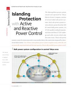
Hybrid Power + Control solution An innovative and compact solution allowing power and signal delivery in one connector. High performance & secure solution
Compatible with RS 485 (2 twisted pairs + braid) Terminating 120 Ohms resistor Current Breaking Capacity Finger touch proof
UL/IEC qualification time saving
Safety standard oriented UL 1977 & IEC 61 984 qualified
Easy and robust interconnection
Push and Press to release mating system Stainless Steel latch Key Hole design for blind mating High resistance to shocks and vibrations
High outdoor life expectancy
F1 material per UL 746C IP68 / 68K sealing level Moisture proof
UTL Series | 122G1W5 Qualification Time Saving In today’s fast paced environment we are all buying electronic devices with confidence. To achieve such a high level of trust, the legislator put in place a wide variety of safety standards. Some are dedicated to the equipment, some to the connection. SOURIAU designed and qualified the UTL series according to the UL 1977 and IEC 61984 but we also took into account additional requirements.
+
UL 19 1977 & IEC 61 984 Qualified
Additional capabilities ities
7
984
UL 197
IEC 61
o o o o o o o o
Impact resistance Stress relief Flame retardant Finger probe Aging Hot wire Bending Current breaking
In this way, the UTL series is also compliant with ALL equipment standards mentioned below.
=
Easy equipment qualification Now, the qualification of your equipment is much easier. UL201 UL 1995
Heating and cooling equipment
UL 2238
Cable assemblies and fittings for industrial control and signal distribution
IEC 60601
Medical equipment
IEC 61010
Safety requirements for electrical equipment nt for measurement, control, and laboratory use se
IEC 60598
Street lights
UL/IEC 60950
2
Safety standard of industrial equipment
Information technology equipment
UL & IEC Qualification Report
UTL Series | 122G1W5 Description • The UTL Series is a plastic connector range that meets industrial safety standards. • The «Key hole» of the coupling system allows blind mating. In dark conditions the mechanical discriminations allow easy mating to avoid connector damage. • The stainless steel latch coupling system is simple to use. With only 1 finger, connectors are mated with an audible click. • The UTL Series is rated at IP68/69K even in dynamic conditions and remains sealed even when used continuously underwater or cleaned using a high pressure hose while the cable is moving. • The UTL Series uses an outdoor rated material per Underwriters Laboratories. • Cable assembly equipped with DMX + Power cables suitable for outdoor use (PUR or Neoprene outer jacket).
Technical Features Materials • Housing: Thermoplastic • Contacts: 3x #16 + 5x #20
• In accordance with: - UL 1977: UL file number ECBT2.E169916 - IEC 61984: please consult us - C22.2 N°182.3: file number ECBT8.E169916 - IEC60065, IEC60598, UL1598, IEC60320, UL498, UL94 , UL746 , IEC61076-2-103
Electrical
• CN: 13A 600V 10A 277V for CBC use • IEC: 16A 500V 6KV 4 13A 250V 4KV 4 for CBC use • Connector specially designed to be engaged or disengaged in normal use when live or under load • First Mate Last Break contact mating on ground line • Signal lines: RS485 compliant 2.5A 10V • Finger touch proof
• Sealing: - IP68/69K mated with standard contacts • Fluid resistance: - Gas and oil - Mineral oil - Acid bath - Basic bath
• Latch: Stainless steel
• UL: 16A 600V V0 13A 277V for CBC use
color variation due to environmental exposure (F1 material per the UL 746C)
• Halogen free
Environmental • Operating temperature (according to IEC61984): From -40°C to +105°C for connector From -25°C to +60°C for cable assemblies due to cable performances • Flammability rating: UL 94: V-0 for connector UL94: 5VA for thermoplastic UL746C: 5 inch (127mm) end-product flame test • Salt spray: ≥1,000 hours • UV resistant: No mechanical degradation or important
• RoHS compliant
Mechanical • Durability: - 250 mating in CBC (current breaking capacity) use (UL1977; IEC61984) - 500 mating in COC use (IEC61984) - 1,000 matings & unmatings tested • Coupling system: - Sensitive and audible click - Blind mating • Touchproof: IP2X in unmated conditions (connector equipped with socket contacts) 3
UTL Series | 122G1W5
OR
OR Layout
WITH
Connector Part Number Plugs and receptacles have to be equipped with both contact genders. Ground lines will never be equipped with the same contacts between the neutral and phase. Contact type
Part number
Connector type
Male insert with female ground
Female insert with male ground
Crimp contacts supplied separately see page 7
Plug
UTL6122G1W5P
UTL6122G1W5S
Jam nut receptacle
UTL7122G1W5P
UTL7122G1W5S
In line receptacle
UTL1122G1W5P
UTL1122G1W5S
Terminating resistance plug - 120Ω Terminating resistance receptacle - 120Ω
UTL6102G1W5PCDMX
UTL6102G1W5SCDMX
-
UTL1102G1W5PCDMX
UTL1102G1W5SCDMX
Evaluation kit - For more informations see page 14 Wire section
Contact type
Power
Connector Type
Signal
16AWG / 1.5mm² 24AWG / 0.22mm² Crimped contacts Stamped & Formed
14AWG / 2.5mm² 24AWG / 0.22mm²
Accessories
Part number Male insert with female ground Female insert with male ground
Plug
16AWG / 1.5mm² 24AWG / 0.22mm²
In line 14AWG / 2.5mm² 24AWG / 0.22mm² receptacle
Shrink boot
16AWG / 1.5mm² 24AWG / 0.22mm²
Jam nut No accessory 14AWG / 2.5mm² 24AWG / 0.22mm² receptacle
UTL6122G1W5P16AWG UTL6122G1W5P14AWG
UTL6122G1W5S16AWG UTL6122G1W5S14AWG
UTL1122G1W5P16AWG
UTL1122G1W5S16AWG
UTL1122G1W5P14AWG UTL7122G1W5P16AWG UTL7122G1W5P14AWG
UTL1122G1W5S14AWG UTL7122G1W5S16AWG UTL7122G1W5S14AWG
Overmoulded Cable Assembly Part Number Layout
Connector and Overmould type Connector Overmould type
Description In line
122G1W5
Male In line receptacle Female In line receptacle
Straight
Male plug
Straight
Female plug
Straight
Plug * : For other lengths or specific design requirement consult us
4
Straight
Length* 1m
2m
HAUTL12G1W5PS1M HAUTL12G1W5SS1M HAUTL62G1W5PS1M HAUTL62G1W5SS1M
HAUTL12G1W5PS2M HAUTL12G1W5SS2M HAUTL62G1W5PS2M HAUTL62G1W5SS2M
UTL Series | 122G1W5 Dimensions (For mated connector lengths see page 14) Plug - UTL6
In line receptacle - UTL1 31.5
20
28.1
11.3
15.0
26.5
31.9
14
Ø28.8 Front view
Front view
Jam nut receptacle - UTL7 31.5
Terminating resistance plug
20
14
15.0
26.5
27
31.9
70 maxi
Ø28.8
Front view
Front view
Panel cut out
Terminating resistance receptacle
Jam nut receptacle - UTL7
5
.2
22
21
Ø
Ø 27
20
31.9
70 maxi
Front view
1.5
Note: all dimensions are in mm and for information only
5
UTL Series | 122G1W5 Accessories and Tooling Dustcap for plug IP67
Dustcap for receptacle
Handle (without head)
Tool kit
IP67
Part number
Part number
Part number
Part number
UTL612DCG
UTL12DCG
SHANDLES
TOOLKIT
Extraction Tool #16
Insertion Tool #20
Head Crimp Tooling (without handle) Contacts
Part number
Part number
RX2025GE1
RTM205
RM/RC 24W3K(1) RM/RC 20W3K(1) RM/RC 18W3K(1) SM/SC 24WL3(1)(2) SM/SC 20WL3(1)(2) RM/RC 28M1K(1) RM/RC 24M9K(1) RM/RC 20M13K(1) RM/RC 20M12K(1) RM/RC 16M23K(1) RM/RC 14M30K(1) SM/SC 24ML1TK6(1) SM/SC 20ML1TK6(1) SM/SC 16ML1TK6(1) SM/SC 14ML1TK6(1) SM/SC 16ML11TK6(1) RMDXK10D28K RCDXK1D28K RM/RC DX60xxD28K RM/RC DXK10D28 + york090 RM/RC DX60xxD28
Part number of head
Contact size
S20RCM* S20RCM* S20RCM* S20SCM20* S20SCM20* S16RCM20* S16RCM20* S16RCM20* S16RCM20* S16RCM16* S16RCM14* S16SCM20* S16SCM20* S16SCML1* S16SCML1* S16SCML11*
Standard contacts #20 Ø 1mm
Standard contacts #16 Ø 1.6mm
Coaxial contacts #16 Ø 1.6mm
M10S1J with die set & stop bushing
(1): Example of plating, for other plating options see UTL catalog * Heads to be used with handle PN: SHANDLES
+ Handle
6
(2): loose contact
= Head
Complete set
UTL Series | 122G1W5 Contacts
Crimp
#20
Part number Male
Female
Max wire Ø
Max insulator Ø
26-24 22-20 20-18
RM24W3K(1) RM20W3K(1) RM18W3K(1)
RC24W3K(1) RC20W3K(1) RC18W3K(1)
0.80 1.15 1.30
1.60 1.60 2.10
26-24 26-24 22-20 22-20
SM24W3TK6(1)(2) SM24W3S26(1)(2) SM20W3TK6(1)(2) SM20W3S26(1)(2)
SC24W3TK6(1)(2) SC24W3S25(1)(2) SC20W3TK6(1)(2) SC20W3S25(1)(2)
-
0.90-1.60 0.90-1.60 1.20-2.10 1.20-2.10
Machined
30-28 26-24 22-20 22-20 20-16 16-14
RM28M1K(1) RM24M9K(1) RM20M13K(1) RM20M12K(1) RM16M23K(1) RM14M30K(1)
RC28M1K(1) RC24M9K(1) RC20M13K(1) RC20M12K(1) RC16M23K(1) RC14M30K(1)
0.55 0.80 1.15 1.15 1.80 2.30
1.00 1.60 1.80 2.20 3.20 3.20
Stamped & Formed Reeled Contacts
26-24 22-20 18-16 18-16 14
SM24M1TK6(1)(2) SM20M1TK6(1)(2) SM16M1TK6(1)(2) SM16M11TK6(1)(2) SM14M1TK6(1)(2)
SC24M1TK6(1)(2) SC20M1TK6(1)(2) SC16M1TK6(1)(2) SC16M11TK6(1)(2) SC14M1TK6(1)(2)
-
0.90-1.60 1.20-2.10 3.20 3.00 3.20
For jacket diameter from 1.78 to 3.05mm Inner conductor up to 2.44mm diameter
RMDXK10D28 RMDX60xxD28 RMDXK10D28 + york090 RMDX60xxD28
RCDXK1D28 RCDX60xxD28 RCDXK1D28 + york090 RCDX60xxD28
-
-
-
-
-
-
-
-
Contact type
AWG
Machined
Stamped & Formed reeled contacts See note (2) for loose piece
Crimp
#16
See note (2) for loose piece
Coaxial
Cable Multipiece Cable Monocrimp Twisted pair Multipiece Twisted pair Monocrimp
For jacket diameter from 0.64 to 1.45mm Inner conductor from AWG30 to AWG24
(1): Example of plating, for other plating options see UTL catalog (2): For loose piece contact packaging, place "L" in part number. Example: SM20ML1TK6
Note: all dimensions are in mm
REMINDER Plugs and receptacles have to be equipped with both contact genders. EX: UTL6122G1W5P = 2 x SM16M1TK6 (power) + 1 x SC16M1TK6 (ground) + 5 x SM20W3TK6 (signal)
Electrical characteristics
UTL122G1W5 derating curves Current (A)
UL 16A 600V V0 13A 277V for CBC use CN 13A 600V 10A 277V for CBC use IEC 16A 500V 6KV 4 13A 250V 4KV 4 for CBC use
Test conditions Contact used: Machined contacts Wires used: #16 contacts wired onto 1.5mm² or 16AWG conductors #20 contacts wired onto 0.5mm² or 20AWG conductors and powered at 2.5 Amps Current use
35 33 30 28 25 23 20 18 15 13 10 8 5 3 0 0
20
40
60
80
100
Ambient Operating Temperature (°C)
Limited use
120
Not recommended use
7
UTL Series | 122G1W5 Contacts (Continued) Plating Selector Guide Contacts Supplied Separately Electrical characteristics: contact resistance #20 Ø1mm
#16 Ø1.6mm
Machined
Contact size
< 6mΩ #20
Stamped and Formed
< 6mΩ
Machined
< 3mΩ
Stamped and Formed
< 6mΩ
Available platings options (contacts supplied separately) S25 Female contact S26 Male contact S31 S18
#16
#20 and #16
Active part: 0.75μ gold min over 2μ Ni Crimp area: Gold flash over Ni Active part: 0.75μ gold min over 2μ Ni Crimp area: Gold flash over Ni Active part: Gold flash over Ni Crimp area: Nickel Active part: 0.75μ gold min over 2μ Ni Crimp area: 1.3μ tin over Ni Other: Nickel
J
Gold flash over 2μ Ni
D70
Superseded by S31
S6
Superseded by S18
K
Min 0.4μ gold over 2μ Ni
TK6
2-5μ Sn pre-plated
Other platings on request (contacts supplied separately) #16
T
2μm Ni min all over + 3 to 5μm Sn all over
D28
0.75μ gold over Ni
Packaging - Size contacts #20 & #16 Due to the wide variety of applications, contact packaging is offered for small series (bulk package) and high volume production (reeled contacts): Stamped & Formed
• 25 pieces loose package
• 3 000 pieces reeled
Machined contacts
• 50 pieces bulk package
• 1 000 pieces bulk package
Note : 1 000 pieces bulk package available by adding 1000 at the end of the part number: e.g. RC16M23K1000 2 000 pieces reeled package available by adding K at the begining of the part number: e.g. KRC16M23K
8
• 2 000 pieces reeled
UTL Series | 122G1W5
Contact Selector Guide
Machined
Contact size
Wire size Type Machined
#20 Ø1 mm
#16 Ø1.6 mm
Stamped & Formed
Part number
AWG
mm²
Male
26-24
0.13-0.20
RM24W3K (1)
Stamped & Formed
26-24
Machined
22-20
0.13-0.25
SM24W3-
(2)
SM24WL30.32-0.52
Stamped & Formed
22-20
Machined
20-18
0.50-0.93
Machined
30-28
0.05-0.08
Machined
26-24
0.13-0.2
0.35-0.5
Female
Max insulator Ø
RC24W3K
0.80
1.60 max
K
0.90-1.60
TK6 S25 (female) S26 (male)
(1)
SC24W3-
(2)
SC24WL3-
RC20W3K
1.15
SC20W3-(1)
-
SM20WL3-(2)
SC20WL3-(2)
-
RC18W3K RC28M1RC24M9SC24M1-(1) SC24ML1-(2) RC20M13RC20M12SC20M1-(1) SC20ML1-(2) RC16M23-
26-24
0.13-0.25
Machined
22-20
0.32-0.52
Stamped & Formed
22-20
0.35-0.5
Machined
20-16
0.52-1.5
Machined Sealed contact
20-16
0.52-1.5
RM16M25K
RC16M25K
Stamped & Formed
18-16
0.8-1.5
Stamped & Formed
18-16
0.8-1.5
Machined
16-14
1.5-2.5
SM16M1-(1) SM16ML1-(2) SM16M11-(1) SM16ML11-(2) RM14M30SM14M1-(1) SM14ML1-(2)
SC16M1-(1) SC16ML1-(2) SC16M11-(1) SC16ML11-(2) RC14M30SC14M1-(1) SC14ML1-(2)
RM14M25K
RC14M25K
2.0-2.5
Machined Sealed contact
16-14
1.5-2.5
-
RM20W3K
Stamped & Formed
14
-
SM20W3-(1)
RM18W3K RM28M1RM24M9SM24M1-(1) SM24ML1-(2) RM20M13RM20M12SM20M1-(1) SM20ML1-(2) RM16M23-
Stamped & Formed
Available plating see page 34
Max wire Ø
1.60 max
K
1.20-2.10
TK6 S25 (female) S26 (male)
1.30
2.10 max
K
0.55
1.00
K, J
0.80
1.60
K, J
0.89-1.28
Insulation grip
TK6, S31, S18
1.15
1.80
K, J
2.20
1.17-2.08
Insulation grip
TK6, S31, S18
1.80
3.20
K, J
1.80
3.20
K
3.00
No insulation grip
TK6, S31, S18
2.00-3.00
Insulation grip
TK6, S31, S18
2.30
3.20
K, J
3.20
No insulation grip
TK6, S31, S18
2.30
3.20
K
(1) contact reeled (2) loose contact Exemple: RM16M3K - Size #16, Machined, AWG20 wire, gold plating.
REMINDER Plugs and receptacles have to be equipped with both contact genders. Examples: UTL6122W3G1P = 2 x SM16M1TK6 (power) + 1 x SC16M1TK6 (ground) + 5 x SM20W3TK6 (signal) Note: all dimensions are in mm
9
UTL Series | 122G1W5 Assembly Instructions Stripping • Female insulator: Strip external cable sheath, adjust ground cable length • Male insulator: Strip external cable sheath, adjust signal cable lengths • Crimp contacts (see page 12)
8 pos. UTL6122G1W5P - UTL7122G1W5P UTL1122G1W5P
UTL6122G1W5S - UTL7122G1W5S UTL1122G1W5S
47mm
38.5mm
Ground line Female contacts
Ground line Male contacts
L*
41mm
L*
43mm Power lines Male contact
Power lines Female contact
Drain
Drain
Signal lines Male contacts
Signal lines Female contacts
36mm
37mm
Dimensions for information only, stripping dimensions could be adjusted according to the cable type.
Ground contact must be opposite gender than power contact.
Wire Stripping Length Part number Female
Stripping length L* (mm)
RC24W3-/RC20W3-/RC18W3-
4.8
Male #20 - Ø 1mm
RM24W3-/RM20W3-/RM18W3-
#16 - Ø 1.6mm
Machined contact
RM28M1-/RM24M9-/RM20M13-/RM20M12- RC28M1-/RC24M9-/RC20M13-/RC20M12RM16M23-/RM14M30-
RC16M23-/RC14M30-
4.8 7.1
#20 - Ø 1mm Stamped & formed with insulation support
SM24W3-/SM24WL3-/SM20W3-/SM20WL3- SC24W3-/SC24WL3-/SC20W3-/SC20WL3#16 - Ø 1.6mm
SM24M1-/SM24ML1-/SM20M1-/SM20ML1- SC24M1-/SC24ML1-/SC20M1-/SC20ML1SM16M11-/SM16ML11-
Stamped & formed without insulation support
10
4
SC16M11-/SC16ML11-
4 4.65
#16 - Ø 1.6mm
SM16M1-/SM16ML1-
SC16M1-/SC16ML1-
6.35
SM14M1-/SM14ML1-
SC14M1-/SC14ML1-
6.35
UTL Series | 122G1W5
Crimping with SOURIAU Tooling 1) Fully close then release the tool, keep it open. Open the 2 pins.
2) Choose the adapter head (sold separately), keep vertical and slide it into the handle until the mechanical end.
3) Close the two pins simultaneously to maintain the head.
4) Strip the cable properly check the recommended size in the catalog on page 10.
GOOD
WRONG
WRONG
5) Place conductors, with no deterioration, in the contact bucket. All strands to be located in the crimp bucket.
6) Position the contact in the bottom of the tool by checking its orientation. Maintain the wire in position.
7) Tighten sharply the handles to the end of the mechanism (max 175 N). After handles are opened, extract the contact.
8) Control the quality of crimping (see next page).
11
UTL Series | 122G1W5 Assembly Instructions (Continued) Crimping Control One of the key factors which affects the performance of a connector is the way contacts are terminated. Crimped connections are nowadays seen as the best solution to ensure quality throughout the lifetime of the product. Here are some reasons why we recommend this method of termination for UTL connectors:
W
Machined contacts size #20 Ø 1 mm
S&F contacts size #20 Ø 1 mm
Machined contacts size #16 Ø 1.6 mm
Contact type
Die location on heads
RM24W3K RC24W3K
26/24
RM20W3K RC20W3K
22/20
RM18W3K RC18W3K
20/18
SM24WL3TK6* SC24WL3TK6*
26/24
SM20WL3TK6* SC20WL3TK6*
22/20
RM28M1K* RC28M1K*
30/28
RM24M9K* RC24M9K*
26/24
RM20M13K* RC20M13K* RM20M12K* RC20M12K* RM16M23K* RC16M23K* RM14M30K* RC14M30K*
S&F contacts size #16 Ø 1.6 mm
14
14 AWG
SM24ML1TK6* SC24ML1TK6*
26/24
SM20ML1TK6* SC20ML1TK6*
22/20
SM16ML11TK6* SC16ML11TK6* SM16ML1TK6* SC16ML1TK6* SM14ML1TK6* SC14ML1TK6*
* example of plating, for other plating see page 34
12
18 16 18 16
20 18 16 16 14
Stamped & Formed contact
W Wire section range 26 AWG 24 AWG 22 AWG 20 AWG 20 AWG 18 AWG 26 AWG 24 AWG 22 AWG 20 AWG 30 AWG 28 AWG 26 AWG 24 AWG 22 AWG 20 AWG 22 AWG 20 AWG 20 AWG 18 AWG 16 AWG 16 AWG 14 AWG 26 AWG 24 AWG 22 AWG 20 AWG 18 AWG 16 AWG 18 AWG 16 AWG
22/20
H
Machined contact
Active contact part
To ensure that the crimp tooling is performing according to original specifications, it is important to carry out regular checks. A common way to check the performance of tooling is with a simple pull test, ideally using a dedicated electric pull tester. Minimum recommended pull forces are indicated in the tables below:
H
Advantages (Extract from the IEC 60352-2): - Efficient processing of connections at each production level - Processing by fully-automatic or semi- automatic crimping machines, or with hand operated tools - No cold-soldered joints - No degradation of the spring characteristic of female contacts by the soldering temperature
- No health risk from heavy metal and flux steam - Preservation of conductor flexibility behind the crimped connection - No burned, discolored and overheated wire insulation - Good connections with reproducible electrical and mechanical performances - Easy production control.
Height (mm) H (±0.075)
Width (mm) W (±0.075)
0.12 min 0.25 max 0.32 min 0.50 max 0.50 max 0.82 max 0.12 min 0.25 max 0.32 min 0.50 max 0.05 min 0.08 max 0.12 min 0.25 max 0.32 min 0.50 max 0.32 min 0.50 max 0.50 max 0.82 max 1.50 max 1.50 min 2.50 min 0.12 min 0.25 max 0.32 min 0.50 max 0.82 min 1.50 max 0.82 min 1.50 max
Tensile straight test (mini) 15 N 32 N 40 N 60 N 60 N 90 N 15 N 32 N 40 N 60 N 11 N 11 N 15 N 32 N 40 N 60 N 40 N 60 N 60 N 90 N 150 N 150 N 230 N 15 N 32 N 40 N 60 N 90 N 150 N 90 N 150 N
0.95
1.27
1.26
1.78
1.35
1.86
0.80
1.49
1.01
1.53
1.14
1.41
1.15
1.41
2.50 max
230 N
Section (mm²)
Tooling head part number
S20RCM
S20SCM20
S16RCM20 1.26
1.76
1.66 1.80 1.96 2.10 2.30
2.18 2.28 2.43 2.68 2.78
0.84
1.50
1.02
1.54
1.32 1.36 1.49 1.7
2.09 2.10 2.02 2.05
1.79
2.58
S16RCM16 S16RCM14
S16SCM20
S16SCML11
S16SCML1
UTL Series | 122G1W5
UTL6 or UTL1 Assembly • • • •
Strip wires (see page 10) Crimp contacts (see page 11) Place all the contacts inside the corresponding cavities Manually push each contact, or use our tool (RTM205 for #16 contacts), until audible click. Check each contact retention, with two finger retraction • Do an overmolding on the wired set or use heat shrink boot UTL6
UTL6
UTL1
UTL1
UTL7 Assembly (Mounting Suggestion) • • • • •
Slide nut over the wires Strip wires (see page 10) Crimp contacts (see page 11) Place all the contacts inside the corresponding cavities Manually push each contact, or use our tool (RTM205 for #16 contacts), until audible click. Check each contact retention, with two finger retraction • Seat o-ring, place receptacle in the panel cut-out (see dimension page 5) • Tighten jam nut torque: 2.5 Nm maxi, tightening tool: 7/8"
O-ring
Jam nut
Panel thickness: 3mm max
Final view
O-ring
13
UTL Series | 122G1W5 Mated Connector Length UTL7 + UTL6
UTL1 + UTL6 135 mm maxi
91 mm maxi
Evaluation Kit 8 Contacts Part Number (122G1W5)
AWG
mm²
UTL6122G1W5S
UTL1122G1W5S
UTL1122G1W5P
UTL1122G1W5S
UTL7122G1W5P
UTL7122G1W5S
Heat shrink boot
SM20WL3S26
SC20WL3S25
SM24WL3S26
SC24WL3S25
SM16ML1S31
SC16ML1S31
SM14ML1S31
SC14ML1S31
Kit contains
Male power
16
1.5
1
-
-
-
-
-
1
2
-
5
-
3
2
-
-
Plug
Male power
14
2.5
1
-
-
-
-
-
1
2
-
5
-
-
-
3
2
UTL6122G1W5S16AWG
Plug
Female power
16
1.5
-
1
-
-
-
-
1
-
2
-
5
2
3
-
-
UTL6122G1W5S14AWG
Plug
Female power
14
2.5
-
1
-
-
-
-
1
-
2
-
5
-
-
2
3
UTL1122G1W5P16AWG
Inline receptacle
Male power
16
1.5
-
-
1
-
-
-
1
2
-
5
-
3
2
-
-
UTL1122G1W5P14AWG
Inline receptacle
Male power
14
2.5
-
-
1
-
-
-
1
2
-
5
-
-
-
3
2
UTL1122G1W5S16AWG
Inline receptacle
Female power
16
1.5
-
-
-
1
-
-
1
-
2
-
5
2
3
-
-
UTL1122G1W5S14AWG
Inline receptacle
Female power
14
2.5
-
-
-
1
-
-
1
-
2
-
5
-
-
2
3
UTL7122G1W5P16AWG
Jam nut receptacle
Male power
16
1.5
-
-
-
-
1
-
-
2
-
5
-
3
2
-
-
UTL7122G1W5P14AWG
Jam nut receptacle
Male power
14
2.5
-
-
-
-
1
-
-
2
-
5
-
-
-
3
2
UTL7122G1W5S16AWG
Jam nut receptacle
Female power
16
1.5
-
-
-
-
-
1
-
-
2
-
5
2
3
-
-
UTL7122G1W5S14AWG
Jam nut receptacle
Female power
14
2.5
-
-
-
-
-
1
-
-
2
-
5
-
-
2
3
Part number
Connector type
Gender
UTL6122G1W5P16AWG
Plug
UTL6122G1W5P14AWG
Note: all dimensions are in mm and for information only
14
Wire section
UTL Series | 122G1W5
•
Evaluation Kit – Assembly Instructions The boot is semi-flexible and heat-shrinkable with a moldable adhesive inner lining. • Place the heat shrink boot over the cable ò • Place the contacts in their cavities, checking the retention by slightly pulling the cable ù • Clean the connector surface and the cable jacket with isopropyl alcohol (Note: It is advised to rub the jacket with sand paper and clean the jacket before shrinking the boot) • Position the boot over the rear threads ä • Heat the boot with a heat gun: minimum shrink temp: 80°C - minimum full recovery temp: 110°C make sure to apply the heat evenly around the boot. Starting by applying the heat from the rear of the connector. ë Do not apply excessive heat, as it will damage the connector and/or boot. • Let the boot cool down ö • Check for good retention and the boot glue grip ü. For stripping and crimping information, please see page 10
ò
ù
ä
ë
ö
ü
15
For further information contact us at
[email protected] or visit our web site www.souriau-industrial.com
16
Any duplication is prohibited, unless approved in writing.
PNUTL122G1W5EUSEN03 © Copyright SOURIAU 2015 - All information in this document presents only general particulars and shall not form part of any contract. All rights reserved to SOURIAU for changes without prior notification or public announcement.
UTL Series | 122G1W5