HVAC Clinic
Refrigeration Components
Table Of Contents
Introduction ............................................................................................................................................ 3 Refrigeration Cycle ................................................................................................................................ 4 Condensers ............................................................................................................................................ 6 Evaporators .......................................................................................................................................... 12 Expansion Device ................................................................................................................................ 17 Accessories .......................................................................................................................................... 20 Compressors ........................................................................................................................................ 23
HVAC Clinics
Draft - Not For Distribution
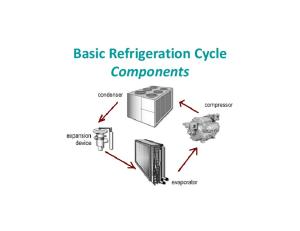
Introduction The primary components of a vapor compression refrigeration cycle include the compressor, condenser, expansion device and evaporator (figure 1). The purpose of this clinic is to discuss in detail each of these components as well as some additional required refrigeration devices. The additional devices include access ports, solenoid valves, isolation valves and filters.
Figure 1. Refrigeration Cycle
WN Mechanical Systems
Refrigeration Components
Page 3 of 29
HVAC Clinics
Draft - Not For Distribution
Refrigeration Cycle First, let look at a quick review of the refrigeration cycle plotted on a pressure enthalpy chart. First, cool, low pressure saturated liquid (A) plus vapor enters the evaporator. The evaporator absorbs heat from the warmer the conditioned fluid, superheating the refrigerant (figure 2). The superheated refrigerant vapor is then drawn in to the suction side of the compressor (B).
Figure 2. Evaporator
The compressor draws in the superheated refrigerant vapor (B) and compresses it to a pressure and temperature (C) high enough that it can reject heat to another fluid. This hot, high-pressure refrigerant vapor then travels to the condenser (figure 3).
Figure 3. Compressor
WN Mechanical Systems
Refrigeration Components
Page 4 of 29
HVAC Clinics
Draft - Not For Distribution
As the refrigerant passes through the condenser, heat is transferred from the hot refrigerant vapor to relatively cool heat rejection fluid. This reduction in the heat content of the refrigerant vapor causes it to desuperheat, condense into liquid, and finally subcool before leaving the condenser (D) for the expansion device (figure 4).
Figure 4. Condenser
Finally, the high-pressure liquid refrigerant (D) flows through the expansion device. The flow through the expansion devices causes a large pressure drop that reduces the pressure of the refrigerant to that of the evaporator. This pressure reduction causes a small portion of the liquid to boil off, or flash, cooling the remaining refrigerant to the desired evaporator temperature (figure 5). The cooled mixture of liquid and vapor refrigerant then enters the evaporator (A) to repeat the cycle.
Figure 5. Expansion Device
WN Mechanical Systems
Refrigeration Components
Page 5 of 29
HVAC Clinics
Draft - Not For Distribution
Condensers The first component to be discussed is the condenser. The condenser is a heat exchanger that rejects heat from the refrigerant to air, water, or some other fluid media. The three common types of condensers are air-cooled, water-cooled, and evaporative. Air cooled condensers generally use propeller-type fans to draw outdoor air over a finned-tube heat transfer surface. The temperature difference between the hot refrigerant vapor that is flowing through the tubes and the cooler outdoor ambient air induces heat transfer. The resulting reduction in the heat content of the refrigerant vapor causes it to condense into liquid. Located in the bottom, last few rows of condenser tubing is the subcooler. In the subcooler, the refrigerant is cooled below the saturation temperature or subcooled (figure 6). Air cooled condensers are very popular in residential and light commercial applications due to the ease of installation and lower cost. Additionally, air cooled condensers are popular in commercial applications in cooler climates or where the cost of water is high. Air cooled condensers have no water and thus do not require any type of freeze protection. However, the saturated condensing temperature within the air cooled condenser must be higher than that of the ambient temperature. This higher saturation temperature and pressure lead to increased energy usage by the system.
Figure 6. Air Cooled Condneser
In addition to ensuring liquid refrigerant enters the expansion device, the subcooler improves system performance. The change in enthalpy (the line from A to B) that occurs in the evaporator is called the refrigeration effect (figure 7). Recall that more energy can be absorbed from a fluid during a change of state than removing temperature from a fluid at a constant state. Without subcooling, the refrigeration effect would be reduced (A’ to B). This reduction in subcooling would in turn reduce the capacity of the system.
Figure 7 WN Mechanical Systems
Refrigeration Components
Page 6 of 29
HVAC Clinics
Draft - Not For Distribution
Another type of air cooled condenser uses a centrifugal fan to draw or blow air over the condensing coil (figure 8). The principal advantage of this design is that the centrifugal fan is capable of overcoming the higher static pressure losses. Propeller fans can overcome very little static pressure. Therefore, if we need to locate the condenser indoors and connect the condenser to a system of ductwork, the centrifugal fan can overcome the additional static pressure. Additionally, due to the higher static pressure capabilities, a centrifugal fan air cooled condenser can utilize energy recovery coils for water economizer cycles.
Figure 8. Centrifugal Fan Condenser
Another variation of the air cooled condenser is the evaporative condenser. Much line an air cooled condenser, refrigerant flow through the tubes of the condenser. However, the main difference is that water is sprayed on the tube surfaces. A portion of the water that is sprayed on the tubes evaporates and release a large amount of heat (called the heat of vaporization). Because the condensing media fluid is changing state, it can release a tremendous amount of energy compared to sensible only cooling (like an air cooled condenser). As the water absorbs heat and changes state, the refrigerant within the tubes condenses. The remaining water falls to the basin and is recalculated with a pump (figure 9).
Figure 9. Evaporative Condenser
Evaporative condensers can greatly increase the efficiency and capacity of a refrigerant system in dry climates. However, the system is susceptible to freezing and the corrosion issues that are inherent in any water cooled system. WN Mechanical Systems
Refrigeration Components
Page 7 of 29
HVAC Clinics
Draft - Not For Distribution
In order to combat the potential for corrosion or scale formation, some evaporative coolers utilize a dry de-superheat coil in series with the wet condenser coil. Scale is formed when there is a high approach between the entering refrigerant temperature and the entering air temperature. Because an evaporative condenser can dramatically cool the effective dry bulb of the air entering the condenser coil, this approach temperature can be high, leading to high levels of scale formation. The dry de-superheater coil reduces the refrigerant temperature before it is allowed to enter the wet section of the coil. This can dramatically reduce the scale formation experienced by an evaporative condenser. A water cooled condenser is a commonly used device on water cooled chillers. Of these, the shell and tube water cooled condenser is the most common. This design utilizes running the condenser water through the tubes while refrigerant vapor fills the shell space surrounding the tubes (figure 10). As heat is absorbed by the cooler condenser water, the refrigerant vapor condenses on the tube surfaces. The condensed refrigerant liquid then falls to the bottom on the shell. At the bottom on the shell, additional tubes (the subcooler) then subcool the refrigerant. At this point, the condenser water temperature has been increased. Either that water has to be disposed of (if using a well) or recycled. If recycled, some type of device must cool the condenser water back to its original entering water temperature.
Figure 10. Water Cooled Condenser
One method of cooling warm condenser water exiting a shell and tube condenser is a cooling tower. Like the evaporative condenser, a cooling tower cools the water via heat of vaporization. Heat of vaporization refers to the energy that is released when a substance vaporizes, or evaporates. As discussed in earlier clinics with regards to refrigerants, when a substance changes state, it releases a tremendous amount of energy. A cooling tower takes advantage of this process by evaporating condenser water. As the water is evaporated, it is cooled. A cooling tower accomplishes this by spraying the warm condenser water over fill in the cooling tower while a propeller fan draws outdoor air upward through the fill (figure 11). The movement of air through the spray causes some of the water to evaporate, cooling the remaining water. This cooled water then falls to the tower sump to be returned to the condenser.
Figure 11. Cooling Tower WN Mechanical Systems
Refrigeration Components
Page 8 of 29
HVAC Clinics
Draft - Not For Distribution
The rate at which the water vaporizes is a function of the ambient wet bulb. Thus, the lower the humidity, the more efficiently cooling towers (and evaporative condensers) perform. As water evaporates, it leaves behind the dissolved solids contained in the condenser water. These dissolved solids and any chemical (if chemical water treatment is used) become concentrated in the sump. To prevent this solution from becoming concentrated and possibly corrosive, water is periodically bled from the sump and an equal amount of fresh water is added. Cooling towers are sized to generally produce between a 7oF and 15oF approach. The approach temperature is defined as the difference between the leaving tower temperature and the ambient wet bulb temperature. Much more than a 15oF approach temperature will lead to chiller oversizing and system inefficiency. Systems which utilize free cooling in lieu of airside economizers should be selected for lower approach temperatures.
Figure 12. Tower Sizing (as provided by spxcooling.com)
Condenser capacity can be controlled by any of three means:
The temperature difference between the refrigerant and the cooling media (air, water, or other fluid) The mass flow rate of the cooling media through the condenser The mass flow rate of the refrigerant through the condenser
Condenser capacity control can be influenced by changing any one of these variables. For example, in air cooled applications, controlling the flow of the condenser fan will change the condenser capacity. Condenser capacity control is an important consideration. As the system load decreases, the condenser heat rejection capacity exceeds the load. As the outdoor temperature decreases, condenser pressure will drop (figure 12). Depending on the amount of capacity control available at the compressor, often this will lead to a drop in evaporator pressure. As evaporator pressure drop, evaporator temperature drops, potentially causing coil frosting a liquid to return to the compressor. Thus, some means of condenser capacity control should be considered.
WN Mechanical Systems
Refrigeration Components
Page 9 of 29
HVAC Clinics
Draft - Not For Distribution
Figure 13. Condenser Capacity Control
For water cooled systems with a cooling tower, three methods of condenser capacity control are recommended. The first method is to use a throttling valve at the condenser outlet. The throttling valve reduces the condenser water flow through the condenser (figure 13). The throttling method has the advantage of being simple and relatively inexpensive. In addition, the throttling method will save some pump energy. The system can be designed to either run on the pump curve or the pump can be controlled by a variable frequency drive. However, the throttling method has the potential to run into pump surge and may run below the tower minimum flow rate at low flows.
Figure 14. Two Way Valve Control
The second method of capacity control for water cooled systems is cooling tower bypass. Tower bypass mixes warm leaving condenser water with cool entering condenser water. Flow to the condenser is constant while flow to the cooling tower is variable (figure 14). The advantage to this system is that the flow through the condenser is constant. The disadvantage is that this system does not allow the system to start under low load conditions (such as coming out of plate and frame free cooling) and you may still run below the tower minimum flow.
WN Mechanical Systems
Refrigeration Components
Page 10 of 29
HVAC Clinics
Draft - Not For Distribution
Figure 15. Cooling Tower Bypass
The third method of capacity control for water cooled system is chiller condenser bypass. Chiller condenser bypass varies the flow through the condenser by bypassing condenser water around the chiller condenser (figure 15). The advantage to this system is that the pump and tower experience constant flow at all load conditions. The downside to this system is that we do not see any energy savings by unloading the pump.
Figure 16. Condenser Bypass
WN Mechanical Systems
Refrigeration Components
Page 11 of 29
HVAC Clinics
Draft - Not For Distribution
In cold climates, either condenser throttling or condenser bypass are preferred. Both of these systems allow the chiller to start under low load, low ambient conditions or in the event of a system coming out of free cooling. Being that the condenser water flow is decreased with both methods; provisions need to be made to bypass the flow switch at low flow conditions. For air cooled systems, some means of varying condenser air flow needs to be implemented. In this case, either discharge dampers of fan variable frequency drives (VFD) may be used. A fan has the advantage of further energy savings at part load conditions (figure 16).
Figure 17. Air Cooled Condenser Pressure Control
Evaporator The second other heat exchange component in the refrigeration cycle is the evaporator. The evaporator absorbs heat from a fluid (air or water) and transfers it to the refrigerant. The cool, low pressure mixture of liquid and vapor refrigerant absorbs the heat from the fluid and boils or vaporizes. There are two primary types of evaporators; finned tube and shell and tube. A finned-tube evaporator includes rows of tubes passing through sheets of formed fins. Cool, low pressure liquid refrigerant flows through the tubes (figure 17). This low temperature refrigerant cools the tube and fin surfaces. Air passes through the coil and comes into contact with the cold fin surfaces. Heat is transferred from the air to the refrigerant, causing the refrigerant to boil.
Figure 18. Evaporator
WN Mechanical Systems
Refrigeration Components
Page 12 of 29
HVAC Clinics
Draft - Not For Distribution
Refrigerant is distributed throughout the coil with a device called a distributor. This refrigerant is a mixture of liquid plus vapor (primarily liquid). The distributor is composed of several equal length and diameter tubes. The distributor is used to maintain refrigerant distribution through multiple coil circuits. Evaporator coils are generally arranged in a counter flow arrangement. In this case, the term counter flow is used to describe an arrangement in which the refrigerant flows in the opposite direction of the air. That is to say, as the refrigerant is headed and passes through the coil, it encounters the warmer entering airstream. Inside these last portions of tubes within the coil, this warmer refrigerant boils and is heated beyond saturation. This is the portion of the coil is which the refrigerant vapor is superheated. This superheated refrigerant vapor (figure 18) ensures that the vapor is completely free of liquid before entering the compressor. Finally, as the refrigerant passes through the tubes of the coil, it collects in a common header. This common header is called the suction header. The suction header is then piped to the compressor
Figure 19. Evaporator Coil
If water is the conditioned media, a shell and tube is commonly used. In a direct expansion (DX) shell and tube evaporator, the cool low pressure liquid plus vapor refrigerant flows through the tubes and water fills the shell space surrounding the tubes. As the heat is transferred from the refrigerant to the water, the refrigerant boils inside the tubes. This boiled refrigerant vapor is then drawn into the compressor (figure 19). Baffles within the shell direct the water in a rising and falling flow path over the tubes that carry the refrigerant. This results in turbulence that improves heat transfer. Another type of similar heat exchanger is the flooded shell and tube evaporator. In contrast to the DX evaporator, in a flooded shell and tube evaporator, the water flows through the tubes and the refrigerant boils on the outside of the tubes.
Figure 20. DX Evaporator WN Mechanical Systems
Refrigeration Components
Page 13 of 29
HVAC Clinics
Draft - Not For Distribution
The methods of evaporator capacity control are similar to that for condenser control. The laws of heat transfer do not change. Evaporator capacity can be controlled by any of three means:
Temperature difference between refrigerant and the media (air or water) being cooled The mass flow rate of the air or water through the evaporator The mass flow rate of the refrigerant through the evaporator
The refrigeration capacity must constantly balance with the change in the system load. With constant volume systems, the airflow remains constant while the temperature difference is variable. With variable volume system, the temperature difference is constant while the airflow is variable. As these loads change, the refrigeration load must change in response. This is typically can be accomplished by one of two means. The first is to start and stop compressors. The second is to design the systems with compressor capable of unloading. The staging or unloading of the compressor in conjunction with the control of the expansion valve (which maintains refrigerant flow and thus superheat) balance the system. If a refrigeration system contains multiple circuits, the refrigeration flow must be divided in some way at the evaporator. Multiple circuits provide redundancy, load control and accurate expansion valve control at part load. The common methods of circuiting finned tube evaporators include face split, row split and intertwined. The face-split coil configuration is split into parallel sections. A portion of the air passes through the top section, the remainder passes through the bottom section. A face split arrangement is analogous to stacking two coils. The two airstreams mix downstream of the coil (figure 20).
Figure 21. Face Split Evaporator Coil
WN Mechanical Systems
Refrigeration Components
Page 14 of 29
HVAC Clinics
Draft - Not For Distribution
A face split arrangement is preferred in situations where humidity control is particularly important. Face split arrangements should only be used with constant volume systems. With a face split arrangement, when one circuit is deactivated, the other maintains its design leaving air setpoint (figure 21). While the leaving air temperature is variable at part load (67.5oF in the example below), one coil continues to remove latent energy due to its lower leaving dry bulb (55oF in the example). In dry climates, or variable air volume systems, face split arrangements are not generally recommended.
Figure 22. Face Split One Coil Off
A row split arrangement splits the coils vertically down the center of the coil. It is analogous to having to coils in series. In the case of a row split arrangement, at part load, the downstream portion of the coil will remain active while the upstream portion of the coil is deactivated (figure 22). A row split arrangement is suitable for constant volume or variable volume applications. However, both the face split and row split arrangements have the disadvantage of being less efficient at part load. This is due to the fact that the coil heat exchange surface is being cut in half for each method.
Figure 23. Row Split
WN Mechanical Systems
Refrigeration Components
Page 15 of 29
HVAC Clinics
Draft - Not For Distribution
The last type of arrangement is the intertwined circuiting method. The intertwined circuit method feeds refrigerant to every other tube (figure 23). Intertwined circuiting has the advantage of increasing the part load efficiency of the system as the tubes are fed to the entire heat exchanger surface. In addition, because the refrigerant sees all the tubes in the system, frosting is less of an issue at part load.
Figure 24. Intertwined Circuiting
A shell and tube evaporator, like a finned tube coil, may also contain multiple circuits. It also uses an expansion device to control capacity and superheat. However, generally capacity control is controlled by unloading or cycling of compressors.
Figure 25. Shell & Tube with Multiple Circuits
WN Mechanical Systems
Refrigeration Components
Page 16 of 29
HVAC Clinics
Draft - Not For Distribution
Expansion Devices The expansion device is used to maintain the pressure difference between the condenser and the evaporator (figure 25). With this drop in pressure, we get a corresponding drop in temperature that allows the evaporator temperature to be low enough to absorb heat from the conditioned media (air or water). Maintaining this pressure differential also allows us to maintain a high enough pressure (and thus temperature) in the condenser to reject heat to the ambient air or condenser water. Several types of expansion devices are commonly used in refrigeration systems. Those devices include thermostat expansion valves, electronic expansion valves, orifices and capillary tubes. For the purposes of this discussion, we will focus on thermostatic expansion devices. Other expansion devices operate on similar principles.
Figure 26. Expansion Device
A thermostatic expansion valve maintains a pressure difference between the evaporator and condenser and controls the quantity of liquid refrigerant entering the evaporator. It controls this volume of refrigerant by measuring superheat (B’ to B). By maintaining superheat, we ensure that only vapor enters the compressor. Liquid refrigerant is non-compressible and can wash compressor bearings dry, leading to premature compressor failure. By controlling the quantity of liquid refrigerant entering the evaporator, the thermostatic expansion device ensures that refrigerant will be completely vaporized within the evaporator (B’) and maintains the proper amount of superheat in the system (figure 26).
Figure 27 WN Mechanical Systems
Refrigeration Components
Page 17 of 29
HVAC Clinics
Draft - Not For Distribution
If the expansion device fails to allow enough refrigerant flow into the evaporator, it vaporizes too quickly. The result is that the rest of the evaporator is filled with vapor, reducing the refrigeration effect (figure 27). Recall that the evaporator absorbs far more energy as refrigerant changes state as compared to refrigerant remaining in the same state. If much of the coil contains vapor, it is going to reduce the capacity absorption capability of the coil.
Figure 28
Conversely, if the expansion device allows an excessive flow of refrigerant into the evaporator, it will fail to completely vaporize the refrigerant. The result is that liquid refrigerant is allowed to enter the suction line and eventually the compressor (figure 28). This liquid compressor is non-compressible and will eventually lead to premature compressor failure.
Figure 29
A typical TXV is connected to a distributor, a remote bulb and an external equalizing line. The distributor distributes refrigerant to the coil. The remote bulb is attached to the suction line. It senses the refrigerant valor leaving the coil. The bulb is charged with refrigerant and as heat is transferred from the suction line to the bulb, the refrigerant inside the bulb vaporizes. The boiling vapor produces pressure which acts on the positive or upper side of the expansion device diaphragm. If the evaporator coil produces more than 2-3oF of equivalent pressure loss, an external equalizing line is required. The equalizing line is tapped into the suction line downstream of the bulb. The pressure from the equalizing line acts on the opposite side of the diaphragm. The last critical component of the expansion device is the adjustable spring. The spring applies a force to the lower side of the diaphragm (figure 29).
WN Mechanical Systems
Refrigeration Components
Page 18 of 29
HVAC Clinics
Draft - Not For Distribution
Figure 30. TXV Piping
For example, assume that an increasing system load causes the refrigerant within the coil to vaporize at a faster rate. This moves the point at which the refrigerant becomes completely vaporized from A to B. The increased superheat results in the refrigerant vapor leaving the evaporator at a higher temperature. The increased superheat causes the remote bulb to transmit a higher pressure to the top side of the TXV diaphragm, causing the valve to open further and allow more refrigerant to flow into the evaporator. This increased flow of refrigerant moves the point of complete vaporization back toward A, until the desired superheat condition is reestablished. The opening and closing forces within the valve equalize at a refrigerant flow rate that balances the new system load. Conversely, a decreased system load slows the rate at which the refrigerant vaporizes, moving the point of complete vaporization toward C. The resulting reduction in superheat creates a lower pressure inside the remote. This in turn decreases the pressure on the top side of the diaphragm. This causes the valve to begin to close, reducing the flow of liquid refrigerant into the evaporator. The reduction in refrigerant flow moves the point of complete vaporization back toward A, reestablishing the desired superheat condition (figure 30).
Figure 31. TXV Operation
A typical built up refrigeration system is designed to operate between 8 oF to 12oF superheat. Too much superheat can cause a number of adverse reactions. First, it will decrease the system capacity and efficiency. It is effectively decreases the amount of coil that experiences a change of state. Second, it can cause compressor damage by overheating the compressor motor windings. Finally, the increased pressure drop at the expansion device lowers the suction pressure, leading to possible coil frosting. Too little superheat superheat will cause liquid to be conveyed to the compressor. This liquid refrigerant will ultimately damage the compressor. WN Mechanical Systems
Refrigeration Components
Page 19 of 29
HVAC Clinics
Draft - Not For Distribution
Too Much Superheat:
Loss of capacity and efficiency Compressor Damage Frosting
Too Little Superheat:
Compressor damage due to liquid refrigerant
Accessories A number of refrigerant accessories are used in a typical refrigeration system. The first is a solenoid valve. A solenoid valve is used to stop the flow of refrigerant within the system. These valves are magnetically operated (figure 31). An electric winding controls the opening and closing of the valve. The valve is typically a normally-closed type of valve so that when the power is de-energized, the valve closes. Applying power to the solenoid valve opens that valve.
Figure 32. Solenoid Valve
A solenoid valve is used to control the flow of refrigerant to the coil as the system loads and unloads. There is usually one solenoid valve per circuit. As the compressors on a circuit are de-energized (as the system unloads), the solenoid valve is closed, shutting of refrigerant flow to that portion of the evaporator (figure 32).
Figure 33. Controlling Staging with Solenoid Valve
A second option function of a solenoid valve is to create a pump down cycle. A pump down cycle prevents refrigerant from migrating to the evaporator when the system is shut down. When a system is off, the vapor refrigerant drops in temperature and returns to a liquid state. This liquid refrigerant can drain into the evaporator and suction line. When the system is started, this liquid refrigerant would then be drawn into the compressor, damaging the system. The intent of a pump down cycle is to prevent this from happening by pumping the refrigerant to the high side of the system (figure 33). This is accomplished by allowing the compressor to run for a short period of time with the solenoid valve closed. The refrigerant is pumped from the low side of the system (the evaporator and suction line) to the high side of the system (the discharge, condenser and liquid line). The compressor is stopped with a pressure sensor in the low side of the system reaches a pre-determined setting.
WN Mechanical Systems
Refrigeration Components
Page 20 of 29
HVAC Clinics
Draft - Not For Distribution
Prior to starting the system, the solenoid valve is opened. This allows the pressure on the low side of the system to normalize. The solenoid valve is installed as close to the expansion device as possible.
Figure 34. Pumpdown Cycle
Upstream of the solenoid valve, a liquid line filter drier should be installed. The liquid line filter drier prevents moisture and foreign matter from entering the expansion device and solenoid valve (figure 34). This moisture (in the form of water) and foreign material in introduced during the installation process. The presence of these materials can cause problem with the operation of the system. When water is mixed with refrigerant and oil, acids are formed. These acids can damage the compressor and valves. In addition, foreign material such as brass and copper can act as a catalyst in chemical reactions that create acids that can corrode the system. To prevent the buildup of these materials, the system should be flushed with nitrogen during the brazing process. This flushing process will eliminate much of the buildup of foreign matter.
Figure 35. Liquid Line Filter Drier WN Mechanical Systems
Refrigeration Components
Page 21 of 29
HVAC Clinics
Draft - Not For Distribution
Other common accessories include a moisture indicating sight glass, shutoff valves and access ports (figure 34). The moisture indicating sight glass is installed in the liquid line, between the solenoid valve and expansion valve. The sight glass permits the operator to observe the condition of the refrigerant prior to entering the expansion valve. The sight glass indicates the moisture level in the system and can be used to detect the presence of bubbles in the liquid line. This would indicate that some of the liquid refrigerant has flashed into vapor upstream of the expansion valve. As discussed earlier, vapor entering the expansion device can cause erratic system operation. The sight glass can be used to alert the operator of such conditions. Shutoff valves are used to isolate critical components of the refrigeration system. Additionally, they can be used to isolator the refrigerant charge in the system for servicing. Common uses of shutoff valves include:
Isolating the charge in the condenser for service access Isolating the compressor from the system for service and replacement Isolating the liquid line filter drier Isolating the suction line filter drier for removal after contaminants have been removed following a compressor burnout
Finally, the last accessory is the access port. Most systems must include three access ports. The first access port should be located in the liquid line to charge the system. It is also used to measure the amount of subcooling in the system. A second access port should be located at the discharge of the evaporator near the equalizer line. This access port is used to measure superheat and to adjust the expansion device. Finally, the third access port should be located near the suction of the compressor. This access port is used to measure compressor suction pressure.
WN Mechanical Systems
Refrigeration Components
Page 22 of 29
HVAC Clinics
Draft - Not For Distribution
Compressors Four types of compressors are used primarily in the refrigeration industry (figure 35). Those are reciprocating, scroll, helical rotary and centrifugal compressors. Reciprocating compressors have been used in the industry for decades. A reciprocating compressor is similar to that used in automobile engines. The compressor utilizes pistons, cylinders, rods, a crankshaft and valves. In the downstroke, refrigerant is drawn into the cylinders. It is then compressed on the upstroke. Scroll and helical rotary compressors are slowly replacing the reciprocating compressor. They contain approximately 70% fewer moving parts and are thus much more reliable and efficient. Like the reciprocating compressor, refrigerant is compressed from a larger volume to a smaller volume. All three compressor act on the principle of positive displacement, or shrinking the volume of refrigerant. Finally, a centrifugal compressor acts on the pricinple of dynamic compression. Dynamic compression involves converting kinetic energy (velocity) to static energy (pressure).
Figure 36. Compressors
As mentioned earlier, reciprocating compressor act on the principle of positive displacement compression. Refrigerant vapor is compressed by a piston that is housed inside a cylinder. A very fine layer of oil prevents refrigerant vapor from escaping through the mating surfaces. The piston is connected to a crankshaft by a rod. As the crankshaft rotates, it causes the piston to travel back in forth in a linear manner inside the cylinder. On the downstroke (intake stroke), refrigerant is draw into the cylinder (figure 36). During the downstroke, the suction valve is open, allowing refrigerant vapor into the cylinder. When the refrigerant pressure exceeds the suction pressure, the intake suction valve is closed. During the upstroke (compression stroke), the suction valve is closed and the refrigerant vapor is compressed, increasing its pressure and temperature. When the pressure inside the cylinder exceeds the discharge pressure, the discharge valve is force open and the compressed refrigerant vapor leaves the cylinder.
Figure 37. Reciprocating Compressor WN Mechanical Systems
Refrigeration Components
Page 23 of 29
HVAC Clinics
Draft - Not For Distribution
Much like the reciprocating compressor, the scroll compressor works by gradually shrinking the volume of refrigerant within the compressor (positive displacement). The scroll compressor uses two scroll configuration plates mated face to face. The upper scroll is called the stationary scroll and contains the discharge port. The lower scroll is called the driven scroll and is connected to a motor shaft and bearing assembly. The refrigerant vapor is drawn through the outer edge of the scroll assembly. The lower scroll’s shaft is offset, causing an orbiting motion. This orbiting motion causes the mated scrolls to form pockets of refrigerant vapor. As the orbiting motion continues, the pockets of vapor continually decrease in volume and move toward the discharge port at the center of the upper assembly. A total of three revolution of the motor shaft are required to complete a single compression cycle (figure 37).
Figure 38. Scroll Compressor
Similar to the scroll compressor, the helical rotary compressor traps the refrigerant vapor and compresses it by decreasing the volume of the refrigerant. The majority of helical rotary compressor designs use two mating screw rotors to perform the compression process. The male rotor is driven by the compressor motor. The lobes of the male rotor make contact and drive the female rotor, causing the two rotors to counter rotate. Refrigerant vapor enters the compressor housing through the intake port and fills the pockets formed by the lobes of the rotors (figure 38). As the rotors turn, they push these pockets of refrigerant toward the discharge end of the compressor. The continued rotation of the rotors forces the refrigerant to meshing point. It is at this point that the refrigerant begins to compress (point D). Finally, when the pockets of refrigerant reach the discharge port, the compressed vapor is released.
Figure 39. Helical Rotary Compressor
Finally, the centrifugal compressor operates on an entirely different principle of compression knows as dynamic compression. During dynamic compression, kinetic energy is converted to static energy. The main component of the centrifugal compressor is the impeller. Refrigerant is drawn into the compressor at the center of the impeller. The center of the impeller is fitted with blades that draw refrigerant vapor into radial passages that are internal to the impeller body. The rotation of the impeller causes the refrigerant vapor to accelerate within these passages, increasing its velocity and kinetic energy. The accelerated refrigerant vapor leaves the impeller and enters the diffuser passages. These passages start out small and become larger as the refrigerant travels through them. As the size of the diffuser passage increases, the velocity, and therefore the kinetic energy of the refrigerant decreases. Recall from the discussion of duct design the principle of velocity regain. Velocity regain dictates that as the velocity pressure is WN Mechanical Systems
Refrigeration Components
Page 24 of 29
HVAC Clinics
Draft - Not For Distribution
decreased, the energy is converted to static pressure. The diffusers passages perform the exact same function, increasing the static pressure of the refrigerant. Finally, the refrigerant enters the volute. The volute also becomes larger as the refrigerant travels through it. Like the diffuser, as the size of the volute increases, the kinetic energy is converted to static pressure (figure 39).
Figure 40. Centrifugal Compressor
Capacity control is accomplished by unloading compressors. The method of unloading depends on the type of compressor. Both scroll and reciprocating compressors are commonly unloaded by simply turning the compressor on an off. If multiple stages are required, multiple compressors are installed. In the past, when large reciprocating compressors were common, reciprocating compressors used cylinder unloaders. However, modern refrigeration systems rarely use reciprocating compressors for system that exceed five tons in capacity. Scroll and helical rotary compressors have largely replaced reciprocating compressors for larger refrigeration systems. Thus, cylinder unloading is very uncommon. Helical Rotary compressors can me modulated by either slide valves or variable frequency drives. Finally, centrifugal compressors can be modulated by inlet guide vanes, variable frequency drives or a combination of both. Type Reciprocating Compressor Scroll Compressor Helical Rotary Compressor Centrifugal Compressor
Method Of Unloading On/Off Cylinder Unloaders On/Off Variable Frequency Drive Scroll Separation (Digital Scroll™) Slide Valve Variable Frequency Drive Inlet Guide Vanes Variable Frequency Drive
Scroll compressors are the predominant technology utilized in systems ranging from 5-150 tons. If close tolerance temperature control is required, a modulating compressor should be utilized. Two methods of unloading scroll compressors have emerged in modern refrigeration system designs. The first utilizes a variable frequency drive (either AC or DC powered) to modulate the speed of the compressor. The variable frequency drive may also be referred to as an inverter. As the compressor speed is decreased, the mass flow rate of compressed refrigerant is decreased. Oil management must be carefully considered when designing systems with variable refrigerant flow rates. Typically, manufacturers of scroll compressors that utilize variable frequency drives use high efficiency oil separators at the discharge of the compressor to recover and recycle the systems lubricating oil. In addition, compressor speed is rarely allowed to modulate below 50% of the compressor nominal speed. Due to oil management concerns, the major manufacturers in North America have been slow to adopt the use inverters with scroll compressors. A newer proprietary method of unloading scroll compressors has been developed by Emerson Climate Technologies. This technology, called a Digital Scroll™ compressor, allows the two scroll plates to separate thus eliminating the pressure produced by the orbiting scroll plates (figure 40). WN Mechanical Systems
Refrigeration Components
Page 25 of 29
HVAC Clinics
Draft - Not For Distribution
Figure 41. Digital Scroll Compressor
Capacity control is determined by the amount of time the plates are allowed to remain separated during a 20 second cycle interval. For example, at 50% capacity, the plates will separate for 10 seconds. At 20% capacity, the places will separate for 16 seconds. The advantage of a Digital Scroll™ compressor is that oil management is much less of a concern compared to a scroll powered by a variable frequency drive. This is because a Digital Scroll™ pulses the refrigerant flow. The refrigerant velocity is at 100% when the plates are closed. Conversely, there is nearly zero flow when the plates separate. The disadvantage to a digital scroll compressor is that at part load (typically less than 30%), high frequency noise can be a concern. Both the use of inverters or Digital Scroll™ compressors can result in very tight temperature control (typically less than 0.5oF temperature variation). However, the added cost, oil management and noise associated with variable capacity scroll compressors must be considered. If tight temperature control is not a concern, then compressor cycling becomes the preferred method of capacity control. To explain the operation of compressor cycling, we will use a 40 ton system with (4) 10 ton compressors as an example. Starting with all four compressors enabled the capacity of the system decreases as suction temperature decreases (points A-B). This decrease in capacity occurs due to the change in density of the refrigerant. As suction temperature increases, the suction pressure increases. The corresponding increase in suction pressure increases the density of the refrigerant, increasing the mass moving or pumping effect of the compressor. Thus, higher suction temperatures lead to higher compressor capacity at a constant input.
Figure 42. Staged Unloading WN Mechanical Systems
Refrigeration Components
Page 26 of 29
HVAC Clinics
Draft - Not For Distribution
As the suction temperature reaches a predetermined setpoint (B), a 10 ton compressor is disabled. When the first compressor is disabled, the system only operates with three active compressors and the capacity falls immediately to 30 tons along the three compressor curve (C). As the load continues to decrease, the capacity and suction temperature follow the three compressor curve (D). Here, the second of four compressors is disabled, decreasing the system capacity to approximately 20 tons along the two compressor curve (E). Again, as the load continues to decrease, the capacity and suction temperature follow the two compressor curve (F). Finally, the third of four compressors disables, decreasing the system capacity to approximately 10 tons (G). As capacity further decreases, the system will follow the single compressor curve until the suction pressure approaches 32oF (H). At this point, the last compressor is disabled. However, in comfort cooling applications, the load generally changes slowly in small intervals. For example assume a comfort cooling application in which the load changes from 40 to 35 tons (figure 42). In response to the change in load, one of four compressors is disabled. The capacity of the refrigeration system drops from point B to point C on the 3 compressor curve where it has a pumping capacity equivalent of 30 tons. At this point, the refrigeration load at 30 tons cannot keep up to the system load of 35 tons. Due to the lack of capacity or pumping capability of the refrigeration system, more refrigerant boils in the evaporator (due to the lack of refrigerant flow) and the suction temperature increases (point D). While the higher suction temperature increases the capacity making capability of the refrigeration system at D (32 tons), the refrigeration capacity is still short of the system capacity. At this point, the fourth compressor is energized, returning the system to point A on the four compressor curve (A). The process repeats itself and the system cycles between three and four compressor in order to maintain the system load.
Figure 43. Staged Load Matching
Helical rotary compressors are generally used in systems ranging from 150-450 tons. Helical rotary compressor can modulated with either a slide valve or a variable frequency drive. The position of the slide valve along the rotors controls the volume of refrigerant vapor delivered by the compressor. It does this by varying the amount of rotor length actually used for compression (figure 43). By changing the position of the slide valve, the compressor is able to load and unload. Some manufacturers will a variable position slide valve which can precisely match the system load. Other manufacturers use a stepped position slide valve. The stepped position slide valve operates much like the scroll staging example discussed earlier.
WN Mechanical Systems
Refrigeration Components
Page 27 of 29
HVAC Clinics
Draft - Not For Distribution
Figure 44. Helical Rotary Slide Valve
A more efficient method of controlling helical rotary compressors is to utilize a variable frequency drive to modulate compressor speed. A variable frequency drive, while more expensive than a slide valve, greatly increases compressor part load efficiency. Centrifugal compressors are generally used in systems ranging from 250-6000 tons. A centrifugal compressors’ part load capacity can be modulated with inlet guide vanes, a variable frequency drive, or a combination of both. Traditionally, inlet guide vanes were used to control chiller capacity. Inlet guide vanes pre-spin the refrigerant before it enters the impeller passages. This pre-spinning of refrigerant reduces the grab or dynamic energy the impeller can impart on the incoming refrigerant stream (figure 44).
Figure 45. Centrifugal Chiller Inlet Vanes
WN Mechanical Systems
Refrigeration Components
Page 28 of 29
HVAC Clinics
Draft - Not For Distribution
However, newer centrifugal compressor designs have incorporated variable frequency drives (VFD) to modulate the compressor at part load. Centrifugal compressors utilize dynamic compression which lends itself very well to the use of VFD’s. In the past, the cost of VFD’s made them prohibitively expensive to utilize in centrifugal compressor designs. In recent years, the cost of VFD’s has been reduced substantially. In addition, newer centrifugal chiller designs utilize magnetic bearings in order to dramatically improve efficiency, reduce noise and improve reliability. In addition, systems that utilize magnetic drives do not require oil. The oil in a system will coat the heat exchange surfaces (evaporator and condenser) decreasing efficiency. In addition, oil-less systems simplify the machine design (the oil management system is removed) and simplify maintenance. Inlet guide vanes cannot be used in magnetic bearing designs. Furthermore, magnetic bearing machines often operate at motor speeds well above 3600 RPM, requiring the use of frequency drives in order to achieve the required motor speed (figure 45).
Figure 46. Magnetic Levitation
Many magnetic bearing chillers offer the additional benefit of offering the ability to control without any means of head pressure control. Being that the chiller is variable capacity by virtue of design, maintaining evaporator pressure at low ambient conditions is of little concern. In addition, maintaining pressure differential for oil flow is inconsequential being that the system does not contain oil. A typical chiller cannot operate below 57oF entering condenser water temperature in order to maintain oil flow. However, if a chiller can operate without head pressure control, the chiller energy savings can be tremendous. In Reno for example, there are potentially in excess of 4000 hours of operation in which the chiller can operate at extremely high efficiencies (< 0.1 kW/Ton) with entering condenser water temperatures are below 57oF and the water temperatures are too warm to enable waterside free cooling (figure 47). .
Figure 47. Wet Bulb Bin Hours (Reno, NV) WN Mechanical Systems
Refrigeration Components
Page 29 of 29