How to Solve DDR Parametric and Protocol Measurement Challenges
DDR Measurements Page 1
Mar. 2008
Agenda DDR Memory Technology Overview DDR Probing Challenges New BGA Probe Adapters Solves Probing Challenges Protocol Validation Challenges, and Solutions Parametric Measurement Challenges, and Solutions Questions and Answers DDR Measurements Page 2
DDR Measurement Challenges
Mar. 2008
1
DDR Memory Technology Everywhere SO-DIMM (Small Outline Dual In-line Memory Module) for Mobile PC
Embedded Designs for HDTV, printers, phones, projectors, cars, base stations, etc.
FPGA Design
DIMM (Dual In-line Memory Module) for Regular PC
DDR DRAM
DDR Measurements Page 3
Mar. 2008
Comparison for DDR 1, 2, 3 Specification DDR1
Operating Voltage Clock Frequency Data Transfer Rate Pin Count Package Backward Compatibility
1.8 – 3.3 V 100 – 200 MHz 200 – 400 MT/s 184 TSOP/BGA No
DDR2
DDR3
1.8 V 1.5 V 200 – 400 MHz 400 – 800 MHz 400 – 800 MT/s 800 – 1600 MT/s 240 240 BGA BGA No No
DDR Measurements Page 4
DDR Measurement Challenges
Mar. 2008
2
DDR Nomenclature as defined by JEDEC DDR SDRAM Chip Specification (for Embedded)
D D R 3 - 1 6 0 0 DDR Technology Designation
DDR Technology Generation
Data Transfer Rate (MT/s) Clock Rate is ½ Data Transfer Rate = 800 MHz
DDR DIMM Specification (for Computer)
P C 3 - 12800 DDR used in PC Designation
DDR Technology Generation
Memory Bandwidth (MB/s) Data Rate (1600) x 8 = 12,800 MB/s
DDR Measurements Page 5
Mar. 2008
Impact on Design and Validation Clock Speeds reaching 1GHz Parallel buses reaching the speeds of serial technology Tighter timing margins require calibration and bus training for DRAM, controller, and analyzer capture Crosstalk, impedance, EMI, and jitter issues Noise susceptibility Probe load effects are critical
“I’m becoming a microwave designer!”
Memory Speed Roadmap
DDR4 3.2 GT/s DDR3 1.6 GT/s
2010+
DDR2 800 MT/s
2008+
DDR 400 MT/s
2005 SDR 100 MT/s
2002
2000
Benefits of good signal integrity Guarantees interoperability with different vendors Improved device performance More design margin
DDR Measurements
Page 6
Page 6
DDR Measurement Challenges
Mar. 2008
3
Agenda DDR Memory Technology Overview DDR Probing Challenges New BGA Probe Adapters Solves Probing Challenges Protocol Validation Challenges, and Solutions Parametric Measurement Challenges, and Solutions Questions and Answers DDR Measurements Page 7
Mar. 2008
Probing Requirement Memory Controller
DRAM
Ideal Probing Points – DRAM Ballout
DIMM
PCB trace
DIMM Connector
JEDEC defines the DDR spec at the DRAM ballout. To fully comply with the specification, probing is recommended to be made at the DRAM ballout for most accurate results. DDR Measurements Page 8
DDR Measurement Challenges
Mar. 2008
4
Probing Challenges
Where to probe?
If probing at the BGA signals is not difficult enough, new design with higher density and limited board space post an even bigger challenge. Designing special probe points or vias on the board is no longer an option.
DDR Measurements Page 9
Mar. 2008
Alternative Probing Options and Issues for Oscilloscope Probing at the center of the trace
DRAM
Memory Controller
Many engineers will find other alternative points to probe at the DDR signals. One example above is probing at the transmission line. However, there is a risk of signal reflection and other signal integrity issues. DDR Measurements Page 10
DDR Measurement Challenges
Mar. 2008
5
Issues with Current Probing Solution on Logic Analyzer • Complete Protocol validation with the logic analyzer requires access to all the buses. • Current probing method does not address individual DRAM probing • Flying leads and midbus probing methods require design-in footprints and connectors – Not practical for boards with tight board space especially on an embedded system – Tedious setup
DDR Measurements Page 11
Mar. 2008
Agenda DDR Memory Technology Overview DDR Probing Challenges New BGA Probe Adapters Solves Probing Challenges Protocol Validation Challenges, and Solutions Parametric Measurement Challenges, and Solutions Questions and Answers DDR Measurements Page 12
DDR Measurement Challenges
Mar. 2008
6
Ideal Probing with DDR2 and DDR3 BGA Probe Adapters DDR2 BGA Probe Adapter for Scope and Logic Analyzer
DDR3 BGA Probe Adapter for Scope
Key Features and Benefits: • Easiest way to access your DDR signals • Superior signal integrity probing for most accuracy in measurement • Compatible with parametric and protocol measurements
W2631-34A (each ship with a kit of 4 probes)
W2635-36A (each ship with a kit of 10 probes)
DDR Measurements Page 13
Mar. 2008
Key Feature 1: Easiest way to access your DDR signals No designated probe points
DDR2 BGA Probe Adapter
Probe Here
Probe Here
Where to probe? Probe Here
High density board
Probe Here DDR3 BGA Probe Adapter
DDR2 and DDR3 BGA probe adapters provide signal access points. DDR Measurements Page 14
DDR Measurement Challenges
Mar. 2008
7
Key Feature 2: Superior signal integrity probing with embedded
resistors in BGA probe Probe Here
Probe Here
DRAM
DDR2/3 BGA Probe PCB Embedded Resistors
Embedded resistor provides isolation of the probe loading and the live signal.
Embedded resistor isolates the probe loading effect from the sig nals. signals. DDR Measurements Page 15
Mar. 2008
Key Feature 2: Superior signal integrity probing for most
accuracy in measurement
Sample Test Results from Key Customer on DDR3 BGA probe Customer’s Quote: These attenuations of waveforms are acceptable and comprehensible. Therefore, W2635A can be used for the measurements.
Without BGA Probe
With BGA Probe
Probing directly at the signals and BGA probes yield similar res ults. results. DDR Measurements Page 16
DDR Measurement Challenges
Mar. 2008
8
Key Feature 3: Compatible with parametric and protocol
measurements
InfiniiMax Probes
Waveform / Data Analysis with Logic Analyzer
DDR2 and DDR3 BGA Probe Adapters
E5384A & E5826/7A LA Cable Adapters
Parametric Measurement with Infiniium Scopes
Compatible with our scope and logic analyzer probes Page 17
DDR Measurements Mar. 2008
Agenda DDR Memory Technology Overview DDR Probing Challenges New BGA Probe Adapters Solves Probing Challenges Protocol Validation Challenges, and Solutions Parametric Measurement Challenges, and Solutions Questions and Answers DDR Measurements Page 18
DDR Measurement Challenges
Mar. 2008
9
Functional Validation Challenges Signal Integrity issues create inaccurate timing and protocol measurement. We need to be able to access and analyze all the buses at the same time to obtain an overview of the bit error rate and SI issues. Accurate Read and write data capture for protocol analysis. We need to be able to sample at the correct sampling position on both read and write data valid window to enable accurate state capture. Spending a lot of time on the work bench, trying to analyze the raw command, bank address and read/write data from the captured trace.
DDR Measurements Page 19
Mar. 2008
EyeScan Feature for Quick SI Check EyeScan result gives a superior and quick SI insight to all the memory buses including Address, Command, Control and Data.
DDR Measurements Page 20
DDR Measurement Challenges
Mar. 2008
10
Protocol Decode Tool
Protocol Decode provides the following for easy memory bus analysis: Command Bank Address Column Address Read or Write Data
DDR Measurements Page 21
Mar. 2008
NEW DDR3 EyeFinder SW The DDR3 EyeFinder software helps you position the sampling points for accurate read and write data capture. The software triggers on valid read and write commands with your system executing any memory test suite or stimulus program. The software will then display read and write data valid window as a result of the scan.
DDR Measurements Page 22
DDR Measurement Challenges
Mar. 2008
11
Agenda DDR Memory Technology Overview DDR Probing Challenges New BGA Probe Adapters Solves Probing Challenges Protocol Validation Challenges, and Solutions Parametric Measurement Challenges, and Solutions Questions and Answers DDR Measurements Page 23
Mar. 2008
Scope Required Bandwidth for DDR Validation Rise Time Memory App
Signal Rate
Fundamental Calculated Freq Fastest Tr/Tf from JEDEC spec
Real Signal Tr/Tf
Optimum Bandwidth
Most likely Material
DDR1 Up to 400MT/s
200MHz
155ps (20-80%)
600 (20-80%)
600MHz - 1GHz
FR4
DDR2 Up to 800MT/s
400MHz
100ps (20-80%)
200 (20-80%)
2GHz - 4GHz
FR4
DDR3
800MHz
60ps (20-80%)
100 (20-80%)
4GHz - 8GHz
FR4
Up to 1.6GT/s
y No mention of signal rise/fall time or bandwidth specification in JEDEC DDR spec. y Bandwidth requirement is a function of rise time. Rise time is a function of signal slew rate and amplitude. Using the information in spec, the fastest rise time can be calculated. y Although the calculated fastest rise time looks aggressive for silicon, the real performance is much slower. This is due to the cheaper FR4 materials and connectors used in the real product design and manufacturing. y The actual signal bandwidth is lower with the higher signal harmonics filtered. DDR Measurements Page 24
DDR Measurement Challenges
Mar. 2008
12
Challenges That Needs to be Addressed Today •
Probing system response. We have the BGA probes to address signal accessibility. Is that all? Actually, the entire probing system (including the probe and scope) has effect on the measurement results.
•
Read and write signal separation on the same bus. We need to trigger using the controls signals, but sometimes scope channels are not enough to get a stable trigger. We need to do many single acquisitions.
•
Not productive, too much time and effort required. Engineers need to manually making measurements of the signals. The maximum measurements is limited. Too much effort to put all results into a test report.
DDR Measurements Page 25
Mar. 2008
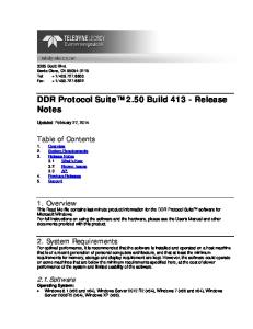
Probing System Response Performance of probing system is a combination of both scope and probe. You need the flattest probing response for full confidence in DDR measurement results. Select a probing where the signals track directly with the signals measured with SMA connection. As DDR signals are mostly single-ended, probing is a major consideration for accurate and repeatable measurement. Agilent DSA91204 + N5381A
Magnitude (dB)
Choose a probing solution you are confidence with. Evaluate its performance if you have to. You need to have the full confidence especially if you are validating a new design.
6.0 5.0 4.0 3.0 2.0 1.0 0.0 -1.0 -2.0 -3.0 -4.0 -5.0 -6.0
Company X+ Various Solder-ins
Solder-in
1 2 3 4 5 6 7 8 9 10 11 12 13 14 15 16 17 18 19
Frequency (GHz)
Magnitude (dB)
Magenta: SMA direct Green: Probing
6.0 5.0 4.0 3.0 2.0 1.0 0.0 -1.0 -2.0 -3.0 -4.0 -5.0 -6.0
High BW 00D High BW 90D Short Solder-in Med Solder-in Long Solder-in 1 2 3 4 5 6 7 8 9 10 11 12 13 14 15 16 17 18 19
Frequency (GHz)
DDR Measurements Page 26
DDR Measurement Challenges
Mar. 2008
13
More InfiniiMax Probe Innovations Need temperature characterization?
N5450A InfiniiMax Extreme Temperature Cable Extension
Solution with Gore Cable Extension specially developed for InfiniiMax Perfect solution for the environmental chamber testing Agilent exclusive solution with 36 inches long (92cm) reach Two Different Operating Temp depending of the probe head N5381A solder-in: -55 to +150°C E2677A solder-in: -25 to +80°C
Need probing with larger pitch size? N5451A InfiniiMax Long Wire ZIF Tip
Wider span than standard ZIF Tip to probe signal like DDR system with larger pitch size. Need to reach to the ground point on the board. Two different wire length: 7 mm (>6GHz) and 11 mm (>4.5GHz)
DDR Measurements Page 27
Mar. 2008
Use InfiniiScan to separate Read and Write signals There is no rule how to use the zones to separate the read or write signals. It depends on the silicon characteristics and DIMM loading which shows distinctive difference between the read and write signals.
High Impedance State DQS read or write normal bits
DQS read or write normal bits High impedance state
DQS read or write preamble bit
Use InfiniiScan ““Zone Zone Qualify Qualify”” to trigger on Read and Write distinctive waveform pattern. DDR Measurements Page 28
DDR Measurement Challenges
Mar. 2008
14
Read-Write Separation – Step 1 A “Must Not Intersect” zone is drawn on the DQS waveform to discard the normal bits or idle state signals.
With the “Must Not Intersect” zone drawn, the scope consistently tracks the preamble DQ signal is tracked at bits of the read and write the beginning of the signals. read or write burst, but not separated yet. DDR Measurements Page 29
Mar. 2008
Read-Write Separation – Step 2 Drawing a “Must Intersect” zone at the upper pre-amble bit voltage isolates the Write separation. Compare the DQS and DQ edges. Write Separation – Edges not aligned
Drawing a “Must Intersect” zone at the lower pre-amble bit voltage isolates the Read separation. Compare the DQS and DQ edges. Read Separation – Edges are aligned
Read and Write separation made easy with InfiniiScan ““Zone Zone Qualify Qualify”” DDR Measurements Page 30
DDR Measurement Challenges
Mar. 2008
15
Debugging Clock Jitter Issues with EZJIT tool
Find Correlation Analyze Jitter spectrum
25MHz oscillator
50MHz oscillator
EZJIT is a great tool to debug clock jitter issues. Analyzing the clock error spectrum, you can identify the source of the clock jitter coupled to your DDR clock signal.
Power switching line
Clock error trend
Comparing the low-pass filtered jitter trend with signals like power line, you can correlate the clock jitter with power switching line with EZJIT.
DDR Measurements Page 31
Mar. 2008
List of JEDEC DDR3 Test Parameters Specification JESD79-3 DDR3 SDRAM Specifications
Test Parameters
Table 26 – Single Ended AC and DC Input Levels (Page 103) Vih(dc), Vil(dc), Vih(ac), Vih(dc) Table 27 – Differential AC and DC input levels (Page 105) VIHdiff, VILdiff Table 28 – Cross Point Voltage for Differential Input Signals Vix (CK, DQS) (Page 105) Table 31 – Single Ended AC and DC Output Levels (Page 109) Voh(dc), Vom(dc), Vol(dc), Voh(ac), Vol(ac) Table 32 – Differential Output Slew Rate (Page 109) VOHdiff(ac), VOLdiff(ac) Table 34 – Output Slew Rate (Single-Ended) (Page 110) SRQse Table 36 – Differential Output Slew Rate (Page 111) SRQdiff Table 37 – AC Overshoot/Undershoot Specification for Maximum peak amplitude for overshoot area, Maximum peak Address and Control Pins (Page 113) area for undershoot area, Maximum overshoot area above VDD, Maximum undershoot area below VSS Table 38 – AC Overshoot/Undershoot Specification for Clock, Maximum peak amplitude for overshoot area, Maximum peak Data, Strobe and Mask (Page 114) area for undershoot area, Maximum overshoot area above VDDQ, Maximum undershoot area below VSSQ Table 66 – Timing Parameters by Speed Bin (Page 153) tCK(avg), tJIT(per), tJIT(cc), tERR(2per), tERR(3per), tERR(4per), tERR(5per), tERR(nper), tERR(nper2), tCH(avg), tCL(avg), tJIT(duty), tAC, tDQSCK, tDQSQ, tQH, tDQSS, tDSS, tDSH, tHZDQ, tHZDQS, tLZDQ, tLZDQS, tWPRE, tWPST, tRPRE, tRPST, tDQSH, tDQSL, tDS(base), tDH(base), tIS(base), tIH(base)
Huge list of DDR3 test parameters that have to be verified. DDR Measurements Page 32
DDR Measurement Challenges
Mar. 2008
16
Setting Up the DDR App for Measurements - 1 Select the DDR speed grade.
Selecting the tests.
Configure the apps before the measurements.
DDR Measurements Page 33
Mar. 2008
Setting Up the DDR App for Measurements - 2 Making sure you have made the right connections to your device and scope. User can choose to repeat the measurements. Run the tests.
Result summary page. Includes margin analysis on how close your device passes of fails the spec. DDR Measurements Page 34
DDR Measurement Challenges
Mar. 2008
17
Example of Automated Measurements Eye-Diagram Analysis
Write Preamble Width
DQ Setup Time
Falling Edge Slew Rate
DDR Measurements Page 35
Mar. 2008
Automated HTML Report Generation
The app automatically generates a HTML report for sharing with others or result archiving purpose.
DDR Measurements Page 36
DDR Measurement Challenges
Mar. 2008
18
Summary • New DDR technology speeds and architecture are driving new design and measurement techniques. • Superior signal integrity and BGA probing technology is required for the most accurate DDR validation. • Validation that would have otherwise been very difficult are made easy through new instrument capabilities • Powerful triggering and signal processing • Automated testing of compliance thru SW applications • Protocol aware calibration and data capture
DDR Measurements Page 37
Mar. 2008
For Additional Information Agilent’s DDR technology webpage: • www.agilent.com/find/ddr BGA Probe Information: • www.agilent.com/find/ddr2bga • www.agilent.com/find/ddr3bga-scope A Time-Saving Method for Analyzing Signal Integrity for DDR Buses Application Note: • http://cp.literature.agilent.com/litweb/pdf/5989-6664EN.pdf • http://www.techonline.com/learning/techpaper/199701791 InfiniiScan Product Info • www.agilent.com/find/InfiniiScan Memory Solution with Logic analyzer: • http://www.home.agilent.com/USeng/nav/-536902586.0/pc.html
DDR Measurements Page 38
DDR Measurement Challenges
Mar. 2008
19
Questions and Answers
DDR Measurements Page 39
Mar. 2008
Backup Information
DDR Measurements Page 40
DDR Measurement Challenges
Mar. 2008
20
DDR2 and DDR3 BGA Probe Model Number DDR2 BGA Probe Adapter for Logic Analyzer and Scope W2631A
DDR2 x16 BGA command and data probe (4 units)
W2632A
DDR2 x16 BGA data probe (4 units)
W2633A
DDR2 x8 BGA command and data probe (4 units)
W2634A
DDR2 x8 BGA data probe (4 units)
E5384A
46-ch single-ended ZIF probe for x8/x16 DRAM BGA probe connect to 90-pin LA cable
E5876A
46-ch single-ended ZIF probe for x16 DRAM data only BGA probe connect to 90-pin LA cable
E5877A
46-ch single-ended ZIF probe for 2 x8 DRAM data only BGA probe connect to 90-pin LA cable
1130/60A
InfiniiMax probe amplifier
N5424A/25A
ZIF probe head and tips
N5381A
Solder-in probe head
DDR3 BGA Probe Adapter for Scope W2635A-010
x8, 10 mm width DDR3 BGA probe adapter for x4 and x8 DRAM package (10 units)
W2635A-011
x8, 11 mm width DDR3 BGA probe adapter for x4 and x8 DRAM package (10 units)
W2636A-010
x16, 10 mm width DDR3 BGA probe adapter for x16 DRAM package (10 units)
W2636A-011
x16, 11 mm width DDR3 BGA probe adapter for x16 DRAM package (10 units)
1130/60A
InfiniiMax probe amplifier
N5424A/25A
ZIF probe head and tips
N5381A
Solder-in probe head
DDR Measurements Page 41
DDR Measurement Challenges
Mar. 2008
21