SINGLE STAGE YIA ABSORPTION Chillers WITH OPTIVIEW TM CONTROL CENTER OPERATION and maintenance
New Release
Form 155.21-oM1 (510)
YIA MOD D SINGLE STAGE STEAM / HOT WATER WITH OPTIVIEW TM CONTROL CENTER
LD14498
1A1 through 14F3
FORM 155.21-OM1 (510)
IMPORTANT!
Read BEFORE PROCEEDING! GENERAL SAFETY GUIDELINES
This equipment is a relatively complicated apparatus. During installation, operation, maintenance or service, individuals may be exposed to certain components or conditions including, but not limited to: refrigerants, oils, materials under pressure, rotating components, and both high and low voltage. Each of these items has the potential, if misused or handled improperly, to cause bodily injury or death. It is the obligation and responsibility of operating/service personnel to identify and recognize these inherent hazards, protect themselves, and proceed safely in completing their tasks. Failure to comply with any of these requirements could result in serious damage to the equipment and the property in which it is situated, as well as severe personal injury or death to themselves and people at the site.
This document is intended for use by owner-authorized operating/service personnel. It is expected that this individual possesses independent training that will enable them to perform their assigned tasks properly and safely. It is essential that, prior to performing any task on this equipment, this individual shall have read and understood this document and any referenced materials. This individual shall also be familiar with and comply with all applicable governmental standards and regulations pertaining to the task in question.
safety symbols The following symbols are used in this document to alert the reader to areas of potential hazard:
DANGER indicates an imminently hazardous situation which, if not avoided, will result in death or serious injury.
CAUTION identifies a hazard which could lead to damage to the machine, damage to other equipment and/or environmental pollution. Usually an instruction will be given, together with a brief explanation.
WARNING indicates a potentially hazardous situation which, if not avoided, could result in death or serious injury.
NOTE is used to highlight additional information which may be helpful to you.
External wiring, unless specified as an optional connection in the manufacturer’s product line, is not to be connected inside the micro panel cabinet. Devices such as relays, switches, transducers and controls may not be installed inside the micro panel. No external wiring is allowed to be run through the micro panel. All wiring must be in accordance with YORK’s published specifications and must be performed only by qualified Johnson Controls personnel. Johnson Controls will not be responsible for damages/problems resulting from improper connections to the controls or application of improper control signals. Failure to follow this will void the manufacturer’s warranty and cause serious damage to property or injury to persons. 2
JOHNSON CONTROLS
FORM 155.21-OM1 (510)
Changeability of this document In complying with YORK/Johnson Controls policy for continuous product improvement, the information contained in this document is subject to change without notice. While Johnson Controls makes no commitment to update or provide current information automatically to the manual owner, that information, if applicable, can be obtained by contacting the nearest YORK/Johnson Controls Service Office.
It is the responsibility of operating/service personnel as to the applicability of these documents to the equipment in question. If there is any question in the mind of operating/service personnel as to the applicability of these documents, then, prior to working on the equipment, they should verify with the owner whether the equipment has been modified and if current literature is available.
Associated Literature DESCRIPTION
FORM NO.
OPERATION – YIA UNIT
155.21-OM1
INSTALLATION – YIA UNIT
155.21-N1
SERVICE – YIA OptiView Control Center
155.21-M1
RENEWAL PARTS – YIA OptiView Control Center
155.21-RP1
RENEWAL PARTS – YIA UNIT
155.21-Rp2
WIRING DIAGRAM – YIA UNIT
155.21-W1
WIRING DIAGRAM – YIA Field Control Modifications
155.21-W2
WIRING DIAGRAM – YIA Field CoNNECTIONS
155.21-W3
Application Data – Chiller materials for various water qualities
160.00-AD5
nomenclature yIA
ST
1A1
46
C
S COOLING ONLY
HEAT SOURCE ST=Steam HW=Hot Water
UNIT SIZE 1A1 - 14F3
UNIT TYPE YORK IsoFlow Absorption Chiller JOHNSON CONTROLS
VOLTAGE CODE 17=208-3-60 28=230-3-60 46=460-3-60 50=380/400/415-3-50 58=575-3-60
D DESIGN LEVEL SPECIAL S = Std Tubes X = Special Tubes
3
FORM 155.21-OM1 (510)
table of contents Section 1 INTRODUCTION............................................................................................ 7 GENERAL................................................................................................... 7 Section 2 ABSORPTION SYSTEM OPERATION......................................................... 9 GENERAL INFORMATION......................................................................... 9 Evaporator................................................................................................ 9 Absorber................................................................................................... 9 Generator................................................................................................. 9 Condenser................................................................................................ 9 DESCRIPTION OF MAJOR COMPONENTS AND SUB-SYSTEMS......... 9 General Condenser Shell Assembly........................................................ 9 Evaporator-Absorber Shell Assembly...................................................... 9 Solution Pump.........................................................................................11 Refrigerant Pump....................................................................................11 Heat Exchanger......................................................................................11 Purge System..........................................................................................11 Controls and Wiring................................................................................11 CONTROL DESCRIPTIONS.....................................................................11 Components in the Control Center.........................................................11 Components of Power Panel..................................................................11 Components External to the Control Center......................................... 12 CONTROL SEQUENCE........................................................................... 13 SYSTEM OPERATION............................................................................. 19 General................................................................................................... 19 Capacity Control.............................................................................. 20 General................................................................................................... 19 Maximum Load Limits at Reduced Condensing Water Temperatures.. 19 Solution and Refrigerant Interchange During Operation....................... 19 Anti-Freeze Line..................................................................................... 22 Chilled Water Control Stability............................................................... 22 Stabilizer Refrigerant Solenoid (2SOL).................................................. 22 Capacity Control Valve Override............................................................ 22 Automatic Decrystallization Control....................................................... 22 DISCUSSION OF SUB-SYSTEM OPERATION....................................... 22 Automatic Decrystallization Feature...................................................... 22 Basic Automatic Decrystallization Piping Circuit – Model YIA, All Sizes... 22 ADC Flush Line...................................................................................... 23 Combination of Basic ADC Piping Circuit and ADC Control Feature.... 23 2SOL – Refrigerant Valve Blowdown..................................................... 23 Section 3 PURGing and non-condensables................................................... 27 NON-CONDENSABLES........................................................................... 27 INTERNAL PURGING WHILE UNIT IS OPERATING.............................. 27 PURGE COMPONENTS.......................................................................... 27
4
JOHNSON CONTROLS
FORM 155.21-OM1 (510)
Section 4 PURGE PUMP OPERATION....................................................................... 33 GENERAL................................................................................................. 33 Cleanliness............................................................................................. 33 Types of Lubricants................................................................................ 33 PURGE PUMP PIPING AND OPERATING VALVES................................ 33 The Principle of Gas Ballast.................................................................. 33 OIL LEVEL DETERMINATION.................................................................. 33 Section 5 PURGE PUMP MAINTENANCE................................................................. 35 VACUUM PROBLEMS.............................................................................. 35 Pressure Determinations....................................................................... 35 Oil Contamination................................................................................... 35 Oil Changes and Oil Levels........................................................... 35 Draining The Pump................................................................................ 35 Flushing The Pump................................................................................ 35 Refilling The Pump................................................................................. 36 SHAFT SEAL REPLACEMENT................................................................ 36 REPAIRING OIL LEAKS........................................................................... 36 Location, Cause and Effect.................................................................... 36 Repairing Technique.............................................................................. 36 Drive Problems.................................................................................. 36 Section 6 BUFFALO PUMPS...................................................................................... 39 INTRODUCTION....................................................................................... 39 TROUBLESHOOTING.............................................................................. 39 Pump Tripping On Overloads................................................................ 39 Pump Tripping On Thermal Protection.................................................. 39 Unusual Noise/Vibration......................................................................... 39 Pump Overhaul...................................................................................... 39 Section 7 STEAM AND WATER QUALITY CONTROL.............................................. 41 GENERAL.................................................................................................... 41 STEAM/CONDENSATE OR HOT WATER QUALITY................................. 41 TUBE CLEANING........................................................................................ 42 Section 8 UNIT OPERATING PROCEDURES............................................................ 43 GENERAL................................................................................................. 43 START-UP (NORMAL).............................................................................. 43 OPERATING DATA................................................................................... 44 General................................................................................................... 44 Performance Data and Calculations...................................................... 44
JOHNSON CONTROLS
5
Introduction
Section 9
FORM 155.21-OM1 (510)
PTX CHART................................................................................................. 47 READING THE PTX CHART....................................................................... 47 CRYSTALLIZATION..................................................................................... 47 REFRIGERANT CONCENTRATION........................................................... 47 PRESSURE DROP CURVES...................................................................... 53
Section 10 PREVENTATIVE MAINTENANCE.............................................................. 65 CLEANING AND MAINTAINING THE TUBES WITHIN THE SHELLS....... 65 Tubes......................................................................................................... 65 Brush Cleaning of Tubes.................................................................. 65 TROUBLESHOOTING TABLE..................................................................... 66 PREVENTATIVE MAINTENANCE SCHEDULE.......................................... 67 APPENDIX Glossary Of Terms.................................................................................... 69
list of FIGURES FIGURE 1 - COMPLETE CYCLE DIAGRAM...........................................................................................................10 FIGURE 2 - TYPICAL POWER PANEL (60 Hz, NEMA 1 standard unit power panel shown)................ 12 FIGURE 3 - MODEL YIa ABSORPTION UNIT, FRONT VIEW.................................................................................15 FIGURE 4 - system control component locations...............................................................................16 FIGURE 5 - BASIC FLOW DIAGRAM......................................................................................................................18 FIGURE 6 - Evaporator.....................................................................................................................................19 FIGURE 7 - Absorber..........................................................................................................................................19 FIGURE 8 - SOlution Pump................................................................................................................................19 FIGURE 9 - Generator.......................................................................................................................................19 FIGURE 10 - Condenser.....................................................................................................................................20 FIGURE 11 - Solution and refrigerant level variation with load................................................. 21 FIGURE 12 - EVAPORATOR AUX. DRAIN PAN......................................................................................................21 FIGURE 13 - automatic decrystallization feature...............................................................................25 FIGURE 14 - YIA PURGE SYSTEM.........................................................................................................................28 FIGURE 15 - YIA PURGE TANK..............................................................................................................................29 FIGURE 16 - PURGE EDUCTOR............................................................................................................................29 FIGURE 17 - GAS SEPARATOR.............................................................................................................................30 FIGURE 18 - THE COMPLETE ISOflow PURGE SYSTEM.................................................................................32 FIGURE 19 - purge pump piping and valves - normal operation....................................................... 33 FIGURE 20 - MODEL 1402 VACUUM PUMP FOR YORK.......................................................................................37 FIGURE 21 - flow of refrigerant water or lithium bromide through pump............................. 40 FIGURE 22 - acceptable internal unit pressures.................................................................................43 FIGURE 23 - OPERATING DATA SHEET................................................................................................................45 FIGURE 24 - PTX CHART.......................................................................................................................................48 FIGURE 25 - SPECIFIC GRAVITY - CONCENTRATION........................................................................................49 FIGURE 26 - pressure drop curves.............................................................................................................53 FIGURE 28 - pressure equivalents..............................................................................................................73 FIGURE 29 - vacuum units of measurement..............................................................................................73 6
JOHNSON CONTROLS
FORM 155.21-OM1 (510)
section 1 – INTRODUCTION GENERAL This manual contains instructions and information required by the operator for proper operation and pre ventative maintenance of the YORK IsoFlow Absorption Liquid Chillers. Included in this instruction are discussions of the basic principles of operation of Lithium Bromide Absorption Systems and descriptions of the functional operation of major components and sub-systems. Instructions relat ed to the controls and normal operating sequence of the various modifications of the IsoFlow units can be found in YIA Control Panel Operation Manual Form 155.21O1 and YIA Installation Manual Form 155.21-N1.
JOHNSON CONTROLS
1
Procedures and checks to be conducted by the operator are described extensively for all areas of operation. These involve the Pre-Start modes of units, normal operation of units and operational functions related to general performance of the system. Information and guides are given pertaining to care and general maintenance of the unit. A glossary of terms has been included in the back of this manual. Review these definitions in order to be familiar with the concepts found throughout this manual.
7
Absorption System Operation
FORM 155.21-OM1 (510)
THIS PAGE INTENTIONALLY LEFT BLANK
8
JOHNSON CONTROLS
FORM 155.21-OM1 (510)
section 2 – ABSORPTION SYSTEM OPERATION GENERAL INFORMATION The principle of refrigeration is the exchange of heat and, in absorption liquid chilling, there are four basic heat exchange surfaces: the evaporator, the absorber, the generator and the condenser (refer to FIGURE 1). In absorption chilling, the refrigerant is water like any refrigeration system, absorption chilling uses evaporation and condensation to remove heat. To maintain effective evaporation and condensation, absorption chilling employs two shells which operate at different controlled vacuums. The lower shell (Evaporator and Absorber) has an inter nal absolute pressure of about one one-hundredth that of the outside atmosphere - or six millimeters of mer cury, a relatively high vacuum. The vacuum allows water (the refrigerant) to boil at a temperature below that of the liquid being chilled. Thus, chilled liquid entering the evaporator can be cooled for air conditioning or process cooling applications. Evaporator Refrigerant enters the top of the lower shell and is sprayed over the evaporator tube bundle. Heat from the liquid being chilled evaporates the refrigerant. Absorber The refrigerant vapor then migrates to the bottom half of the lower shell. Here the vapor is absorbed by a lithium bromide solution. Lithium bromide solution is basically nothing more than salt water. However, lithium bromide is a salt with an especially strong attraction for water. The mixture of lithium bromide and the refrigerant vapor - called the “dilute solution” - now collects in the bottom of the lower shell. Generator The dilute solution is then pumped through the heat exchanger, where it is preheated by hot concentrated solution from the generator. The heat exchanger improves the efficiency of the cycle by reducing the amount of steam or hot water required to heat the dilute solution in the generator. The dilute solution then continues to the upper shell containing the Generator and Condenser, where the absolute pressure is approximately one-tenth that of the outside atmosphere, or seventy millimeters of mercury. The dilute solution flows over the generator tubes and is heated by steam or hot water passing through the JOHNSON CONTROLS
interior of the tubes. The amount of heat input from the steam or hot water is controlled by a motorized valve and is in response to the required cooling load. The hot generator tubes boil the dilute solution, releasing refrigerant vapor. Condenser The refrigerant vapor rises to the condenser and is condensed by the cooler tower water running through the condenser tubes. The liquid refrigerant flows back to the lower shell, and is once again sprayed over the evaporator. The refrigerant cycle has been completed. Now the concentrated lithium bromide solution flows from the generator back to the absorber in the lower shell, ready to absorb more refrigerant. Its cycle has also been completed. DESCRIPTION OF MAJOR COMPONENTS AND SUB-SYSTEMS YORK IsoFlow Absorption Chillers consist of the following major components and sub-systems: Generator-Condenser Shell Assembly This is the upper of two cylindrical shells, and it contains two tube bundles - the generator and the condens er. The generator is a single pass flooded tube bundle when operated with steam, and may be a one or twopass flooded tube bundle when operated with hot water. The steam or hot water flowing through the tube bundle boils the water vapor from the solution that surrounds the outside surface of the generator tubes. The condens er section of this shell assembly consists of a singlepass tube bundle through which cooling water is circulated (condensing the water vapor boiled off in the generator) and a condenser pan to collect the water. Evaporator-Absorber Shell Assembly This is the lower shell assembly and it also contains two sections, the evaporator and the absorber. The evaporator consists of a single or multi-pass tube bundle, a refrigerant pan, and a refrigerant spray header assembly. The liquid to be chilled (usually water) flows through the tubes to be cooled by vaporization of the liquid refrigerant (water condensed in the condenser). The liquid refrigerant is pumped through the sprays and flows down over the outside surface of the evaporator tubes. 9
2
Absorption System Operation
FORM 155.21-OM1 (510)
model yia standard steam cycle diagram
KEY
HP1
PT1
RT4
CoNDENSER
CoNCENTRATED SoLUTIoN (LiBr)
TowER wATER
VR40
DILUTE SoLUTIoN (LiBr) INTERMEDIATE SoLUTIoN (LiBr)
oUTLET
PT4
HT1
VP10
RT9
CHILLED LIqUID TowER wATER REFRIGERANT LIqUID Low TEMPERATURE
RT7
HoT wATER oR STEAM
REFRIGERANT LIqUID HIGH TEMPERATURE
**PT2
GENERAToR
DILUTE PURGE LIqUID
PURGE TANK
STEAM oR HoT wATER CoNTRoL VALVE
Typ 2 Places GENERAToR
GAS / VAPoR
VS3
VENT
Anti-Freeze Line
To GENERAToR
RT1
VP2
CHILLED wATER oUTLET
RT6
VP4
CHILLED wATER INLET
EVAPoRAToR
***VP1
FRoM GENERAToR
AUToMATIC DE-CRYSTALLIZATIoN PIPE
RT8
RT2
Abs. Press. Gauge
1F
RT5
7 SoL
ABSoRBER
RT3
2SoL (Stabilizer)
Suction Bypass Line
ADC Flush Line
1A1 & 1A2 Units only
VS12
VS20
8 SoL
VR8 VR9
VR11 3SoL (Unloader)
PT3
VR10
3F
VS17
RT10
TowER wATER INLET
REF. PUMP
1-1/2” Purge Absorber Return
oil Trap VP8
SoL PUMP VS13
VS18
VS19
Purge Pump
* orifices may differ between various models. ** PT2 is for Steam units only. *** May differ between various models. Not Installed on Models 5C3, 6C4, 12F1, 13F2, & 14F3 Not Installed on Models 7D1, 7D2, 8D3, 9E2, 10E3, & 14F3
Note: Some orifices may differ between various models.
LD04763
FIGURE 1 - COMPLETE CYCLE DIAGRAM 10
JOHNSON CONTROLS
FORM 155.21-OM1 (510)
The absorber consists of a single or multi-pass tube bundle, the absorber spray header assembly, and the lower part of the shell, which serves as a solution stor age pan. Tower water is circulated through the absorber tubes to cool the lithium bromide solution being sprayed over the outside of the tubes. This aids the absorption process. Solution Pump The unit has one solution pump mounted under the lower shell. This pump transfers dilute solution to the generator from the absorber and, with the aid of an eductor, pumps mixed (intermediate) solution to the absorber sprays. Refrigerant Pump All units have one refrigerant pump mounted beneath the lower shell to recirculate refrigerant to the evaporator sprays and over the evaporator tubes. Heat Exchanger The heat exchanger is mounted under the lower shell to improve system efficiency by transferring heat from the warm concentrated solution (low water content) to the relatively cool dilute solution (high water content) on its way to the generator. This assists both the generator in heating and the absorber in cooling the dilute and concentrated solutions respectively. Purge System YORK absorption systems are designed and manufac tured for extreme leak tightness to ensure against infiltration of non-condensables into the high-vacuum system. Leakage of air into the system will deteriorate the refrigeration capability of the unit as the absolute pressure in the unit rises, and corrosion problems could develop. The purge system provides a means for ridding the unit of any such accumulation of non-condensables. The system consists of a purge header arrangement in the bottom absorber section, a purge eductor, gas separator, purge storage tank, associated piping connections, wiring, solenoid valves, transducers and purge pump. The control logic provides for automatic and continuous purging of non-condensables from the unit. The logic will monitor, track and display non-condensables purging trends. The system allows for manually purging of non-condensables directly from the unit or the purge tank.
JOHNSON CONTROLS
Controls and Wiring An electronic control system is provided with each absorption unit to permit automatic or manual control of the system. Provisions are made for the following: 1. Automatic capacity control involving electronic controls for steam or hot water valves. 2. Safety controls involving flow switches, float switches, low refrigerant temperature cut-out, motor overloads and protective thermostats. 3. Special control features to provide for steam econ omy and for prevention of crystallization. 4. Functional controls which permit operation over a wide range of condenser water temperatures. Components in the Control Center See IsoFlow Control Panel Operation, Form 155.21-O1. Components in Power Panel (see FIGURE 2) 1SW – Service Disconnect Switch This is a non-fused, service disconnect switch. The incoming power lines from the customer-supplied fused disconnect switch or circuit breaker should be connected to terminals L1, L2, and L3 of this switch. 1T – Transformer This is a step-down transformer that reduces the unit's incoming power (primary) down to the required control voltage of 120/115-1-50/60 (secondary). 1FU, 2FU, 3FU – Control Fuses These are used on all 60 Hz standard (NEMA 1) units. 1FU and 2FU are on the primary side of the 1T transformer. The amperage rating of these fuses depends on the unit's voltage. The 3FU fuse is always a 10-amp fuse and is on one leg of the secondary coil of the 1T transformer. It is used for the control panel voltage. 1CB – Circuit Breaker This takes the place of 1FU and 2FU on 60 Hz NEMA 4 units and 50 HZ, 380 volts units. 2CB – Circuit Breaker This takes the place of 3FU on 60 Hz NEMA 4 units and 50 Hz, 380 volts units.
11
2
Absorption System Operation
FORM 155.21-OM1 (510)
1M – Starter/Contactor for Solution Pump This is used on all units. 2M – Starter/Contactor for Refrigerant Pump This is used on all units. 3M – Starter/Contactor for Purge Pump This is used on all units.
MTH1 and MTH2 – Motor Thermostats These are used on all units with Buffalo Pumps. These Klixon type thermostats are imbedded in the motor windings and will open when the motor internal temperature reaches 300°F (150°C) to 392°F (200°C), depending on pump type. The thermostats will automatically reset when the motor windings cool down 27°F (15°C) from the trip point.
1OL thru 3OL – Overloads Each starter/contactor is accompanied by a heater element overload with resetting capability. The designation number of the overload matches the designation number of the starter/contactor. POWER TRANSFORMER
SERVICE DISCONNECT SWITCH
1FU
2FU
3FU
1OL
2OL
3OL
1M
2M
3M
TB2
GROUND LD14568
FIGURE 2 - TYPICAL POWER PANEL (60 Hz, NEMA 1 standard unit power panel shown) 12
JOHNSON CONTROLS
FORM 155.21-OM1 (510)
Control Components External to the Control Center (see Figure 3) Hermetic Motor Thermostats (not shown) The Solution and Refrigerant pump motors are cooled by the circulating fluid. In the case of inadequate cooling, each motor has an internal motor protector of the Klixon type imbedded in the motor windings to protect the motor from damage if overheating occurs. Refer to Section 6 for additional details.
3SOL – Refrigerant Level Solenoid Valve (Unloader Valve) The function of 3SOL is to transfer solution to the refrigerant circuit of the machine. Normally, this is not a desired condition. However, is some situations it is used effectively to allow the unit to stay on line, make it run more stabwle, and keep the pumps from cavitating. Please refer to the OptiView Service Manual, Form 155.21-M1 for additional details on this valve and how it operates.
1F – Refrigerant Level Float Switch This level switch is located in separate chamber on the side of the refrigerant outlet box. Its function is to determine if a refrigerant level is present or not. If the refrigerant level is not present, either from a low chiller load or low tower water temperature, it could cause the refrigerant pump to cavitate, overheat or make the unit cycle on and off. In these cases the unloader solenoid valve (3SOL) will open to allow solution to mix with refrigerant. This mixing will cause the refrigerant level to increase to satisfy the pump needs and sustain unit operation.
4SOL – Automatic Shut-Off Valve (not shown) This valve is a customer supplied and installed valve. It ensures 100% shut-off during a cycling/safety shutdown or a power failure. It works in conjunction with the 6SOL steam condensate drain solenoid valve. For additional details on this valve, if installed, refer to Installation Manual, Form 155.21-N1.
3F – Refrigerant Pump Cutout Float Switch This level switch is located in a separate chamber just below the refrigerant outlet box on the vertical section of pipe leading to the pump. Like the 3F switch, it monitors the refrigerant level to determine if a level is present or not. If no level is detected the control logic will shutdown the refrigerant pump after some programmable refrigerant pump parameters are met.
6SOL – Steam Condensate Drain Solenoid Valve (if applicable) This valve is located on the condensate outlet box of the generator shell, opposite the steam inlet. It is a normally closed (NC) valve and is energized at all times during unit operation. The function of this valve is to stop all steam flow through the generator when the unit is off or during a power failure. This valve is shipped loose with the unit for field installation. See Form 155.21-N1, “IsoFlow Installation Manual” for details on installing this valve, and applicability.
Flow Switches (not shown) Units fabricated at the release of this document will be equipped with factory supplied and mounted analog thermal type flow sensors in the outlet nozzle of the evaporator and condenser sections. These devices will be wired into the control panel so no further installation process is necessary. 1SOL – Motor Coolant Solenoid Valve These are not used on units with Buffalo Pumps. 2SOL – Stabilizer Refrigerant Solenoid Valve The function of 2SOL is to supply refrigerant to the generators solution outlet line to reduce the solution concentration. There are certain conditions in which this valve will open automatically during unit operation. This valve can also be opened manually to facilitate service procedures. Refer to Control Panel Service manual 155.21-M1 for additional detail on this valve and how it operates. JOHNSON CONTROLS
5SOL – Purge Solenoid Valve This valve is no longer used with units that have Welsh vacuum pumps installed from the factory.
HP1 – High Pressure Cutout Switch This digital safety switch is located off the top of the condenser shell, and is hardwired directly into the control panel. It is factory preset to trip the unit when the unit internal pressure reaches 710 mm Hg Abs. It will automatically reset itself when the units pressure reduces to 40 mm Hg Abs. HT1 – High Temperature Cutout Switch This digital safety switch is located on the control panel side of the generator shell with an accompanying thermistor inserted into an adjacent thermowell. It is hardwired directly into the control panel and factory set to trip the unit when the generator shell skin temperature reaches 330°F (165.6°C). It has a manual reset push button and an amber light on the control to indicate it is functioning. 13
2
Absorption System Operation LRT – Low Refrigerant Temperature Cutout Switch This digital safety switch is located on the opposite side of the refrigerant outlet box from the 1F float switch. It has an attached thermistor, which is inserted into a thermowell that is located on the refrigerant line leading out of the bottom of the refrigerant outlet box. The switch protects the unit from freezing refrigerant. It is factory preset to trip at 34°F (1.1°C). It will automatically reset when the temperature difference increases 4°F.
14
FORM 155.21-OM1 (510)
Control Valve (not shown) This valve is used to control the amount of heat energy (steam or hot water) that enters the generator section of the unit. It receives a control signal from the Control Panel to open or close to control the leaving chilled Water Temperature (LCHLT) to the leaving Chilled Water Temperature Setpoint. If the heat source is steam, the maximum inlet temperature is 337°F (169°C). If the heat source is hot water, the maximum inlet temperature is 266°F (130°C).
JOHNSON CONTROLS
JOHNSON CONTROLS
SOLUTION SIGHT GLASS
power panel
OIl TRAP
ABSORBER
EVAPORATOR
GENERATOR
CONDENSER
PURGE SOLUTION GAS REFRIGERANT PUMP PUMP SEPARATOR OUTLET BOX
PURGE TANK
Hi-PressurE CUTOUT SWITCH (HP1)
RUPTURE DISK
LD14500
SOLUTION RETURN FROm GENERATOR
GENERATOR OUTLET BOX
REFRIGERANT Auto Refrigerant Refrigerant OPTIVIEW PUMP DECRYSTALLIZATION Pump CONTROL PANEL PIPE (ADC) Cutout Level switch (1F) switch (3F)
HIGH-TEMP CUTOUT (HT1)
Major Component Location
FORM 155.21-OM1 (510)
2
FIGURE 3 - MODEL YIa ABSORPTION UNIT, FRONT VIEW
15
Absorption System Operation
FORM 155.21-OM1 (510)
PT1 RT9
HT1 PT4
HP1
8SOL
7SOL
RT3
3SOL RT10
2SOL
RT8 LRT
3F
1F
RT2 LD14498
LEGEND 1F Refrrigerant Level Switch 3F Reffrigerant Pump Cutout Switch HP1 HIGH PRESSURe CUTOUT SWITCH HT1 HIGH TEMP. CUTOUT SWITCH PT1 GENERATOR PRESSURE TRANSDUCER PT2 STEAm supply pressure transducer (Steam units only) RT1 TEMPERATURE Sensor leaving chilled water RT2 Temperature sensor auto-decrystallization RT3 Temperature sensor strong solution RT4 Temperature sensor Leaving Tower water RT5 Temperature Sensor Entering Tower Water RT6 Temperature Sensor Entering chilled water RT7 temperature Sensor Steam / hot water supply RT8 Refigerant Temperature Sensor RT9 Refrigerant Temp. Leaving the condenser RT10 STRONG SOLutioN TEMP. LEAVING HEAT EX. 2SOL Stabilizer Refrigerant Solenoid (for decrystallization) 3SOL refrigerant Level Solenoid (unloading) 6SOL Steam Condensate Drain Solenoid valve (NOT Shown) (not applicable on all units) 7SOL Purge tank solenoid 8SOL Purge Pump Solenoid LRT Low refrigerant temperature cutout switch
FIGURE 4 - system control component locations 16
JOHNSON CONTROLS
FORM 155.21-OM1 (510)
6SOL (NOT SHOWN)
2 EVAPORATOR SIGHT GLASSES
RT5
RT1
ld14570
LEFT END of unit
RT4
PT2 RT7
RT6 RT1
ld14569
Right END of unit figURE 4 (CONT'D) – system control component locations JOHNSON CONTROLS
17
Absorption System Operation
KEY
FORM 155.21-OM1 (510)
HP1
PT1
RT4
CoNDENSER
CoNCENTRATED SoLUTIoN (LiBr)
TowER wATER
VR40
DILUTE SoLUTIoN (LiBr) INTERMEDIATE SoLUTIoN (LiBr)
oUTLET
PT4
HT1
VP10
RT9
CHILLED LIqUID TowER wATER REFRIGERANT LIqUID Low TEMPERATURE
RT7
HoT wATER oR STEAM
REFRIGERANT LIqUID HIGH TEMPERATURE
**PT2
GENERAToR
DILUTE PURGE LIqUID
PURGE TANK
STEAM oR HoT wATER CoNTRoL VALVE
Typ 2 Places GENERAToR
GAS / VAPoR
VS3
VENT
Anti-Freeze Line
To GENERAToR
RT1
VP2
CHILLED wATER oUTLET
RT6
VP4
CHILLED wATER INLET
EVAPoRAToR
***VP1
FRoM GENERAToR
AUToMATIC DE-CRYSTALLIZATIoN PIPE
RT8
RT2
Abs. Press. Gauge
1F
RT5
To PURGE SYSTEM
ABSoRBER
RT3
2SoL (Stabilizer)
Suction Bypass Line
ADC Flush Line
1A1 & 1A2 Units only
VS12
VS20
8 SoL
VR8 VR9
VR11 3SoL (Unloader)
REF. PUMP
1-1/2” Purge Absorber Return
oil Trap VP8
SoL PUMP VS13
VS18
Purge Pump
VS19
* orifices may differ between various models. ** PT2 is for Steam units only. *** May differ between various models. Not Installed on Models 5C3, 6C4, 12F1, 13F2, & 14F3 Not Installed on Models 7D1, 7D2, 8D3, 9E2, 10E3, & 14F3
ld13806
FIGURE 5 - BASIC FLOW DIAGRAM 18
7 SoL
PT3
VR10
3F
VS17
RT10
TowER wATER INLET
JOHNSON CONTROLS
FORM 155.21-OM1 (510)
SYSTEM OPERATION (Based On Standard Steam Units – Model YIA) The cycle diagram for Model YIA Steam/Hot Water operated systems is shown in FIGURE 5. The following discussion will describe the absorption system operation generally, in reference to this particular configuration.
Relatively dilute solution from the bottom of the absorber is pumped by the solution pump, through the heat exchanger, where it is regeneratively heated by hot concentrated solution draining from the generator. The solution then travels up to the generator (see FIGURE 8). ABSoRBER
RT3
Liquid, usually water, for air conditioning applications or process applications is chilled as it passes through the evaporator tubes by giving up heat to refrigerant flowing over the outside of the tubes. This heat causes refrigerant to evaporate since it is at a pressure with a corresponding boiling temperature lower than the leaving chilled water temperature. For example, water is chilled from 54°F to 44°F (12°C to 6.6°C) with the evaporator at 6.3 mmHg. absolute pressure which correlates to a 40°F (4.4°C) boiling point (refer to FIGURE 6).
RT1
RT5
TowER wATER INLET
ABSoRBER
SoL PUMP
VS13 VS19
ld13806c
FIGURE 8 - SOlution Pump
Generator tubes are submerged in lithium bromide solution which enters the generator in a dilute condition at one end and leaves concentrated at the opposite end. A portion of the refrigerant is vaporized by steam or hot water flowing through the generator tubes, thus concentrating the solution (see FIGURE 9).
GENERAToR
VS3
Refrigerant vapor in the evaporator is attracted and absorbed by intermediate lithium bromide solution flowing over the outside of the absorber tubes thus diluting the solution. Heat generated in the process (heat of absorption) is removed by condensing water from a cooling tower or other source flowing through the absorber tubes (see FIGURE 7).
VS20
VS18
ld13806a
FIGURE 6 - Evaporator
AUToMATIC DE-CRYSTALLIZATIoN PIPE
RT10
CHILLED wATER INLET
EVAPoRAToR
JOHNSON CONTROLS
VS12
CHILLED wATER oUTLET
RT6
FIGURE 7 - Absorber
3SoL (Unloader)
FIGURE 9 - Generator
STEAM oR HoT wATER CoNTRoL VALVE RT7 HoT wATER oR STEAM **PT2 GENERAToR oUTLET ld13806d
Concentrated solution flows by gravity and pressure dif ferential through the heat exchanger, where it is cooled regeneratively by cooler dilute solution. The heat exchanger has thus improved the efficiency of the system by reducing the amount of steam or hot water required to heat the dilute solution in the generator and the amount of concentrated solution cooling required in the absorber. An intermediate solution, consisting of a mixture of cooled concentrated solution from the generator heat exchanger with dilute solution from the bottom of the absorber, is recirculated over the absorber tubes by the solution pump, with the aid of the eductor, to complete the solution cycle (see FIGURE 7).
ld13806a
19
2
Absorption System Operation
FORM 155.21-OM1 (510)
Refrigerant vapor released from the dilute solution in the generator is condensed on the condenser tubes by giving up its heat of condensation to condensing water passing through the tubes. This condensing water is the same water that was used to cool the absorber (see FIGURE 9). HP1
PT1
RT4
CoNDENSER
TowER wATER
VR40
oUTLET
HT1 RT9
RT7
GENERAToR
**PT2
FIGURE 10 - Condenser
STEAM oR HoT wATER CoNTRoL VALVE HoT wATER oR STEAM GENERAToR oUTLET ld13806E
Condensed refrigerant flows by gravity and pressure differential through an orifice or expansion device to the evaporator. This refrigerant, plus that recirculated by the refrigerant pump, is distributed over the evapo rator tubes to complete the refrigerant cycle. Capacity of the unit is automatically controlled from the temperature of the chilled water leaving the evaporator. The steam or hot water control valve meters the steam or hot water flow to the generator. Refer to FIGURE 5 for complete cycle diagram. Capacity Control The YIA control panel controls the capacity of the unit by throttling the control valve, which in turn regulates heat into the generator section of the unit. In prior YIA chiller controls sensors monitored incoming Cooling Tower Water Temperature (CTWT). Valve positions were controlled based on predetermined reduced temperatures (see Form 155.16-OM1). This feature was kept the unit design solution concentrations in balance so the unit would not crystallize, over dilute, or inhibit refrigerant vaporization at reduced CTWT temperatures.
1. Leaving Chilled Liquid Temperature Control (LCHLT Control) 2. Strong Solution Concentration Control (SSC Control) 3. Limited load by warning conditions. With the introduction of the RT10 sensor, the OptiView panel is now capable of continuous monitoring of the strong solution temperature in the most critical location where it would most likely begin to crystallize. The logic then analize the three control mechanisms and chooses the lowest limit to ensure trouble free operation. Listed below is a brief description of each control mechanism. Leaving Chilled Liquid Temperature (LCHLT) Control The goal of the LCHLT control is to match the leaving chilled liquid temperature with leaving chilled liquid temperature setpoint. It calculates an error value (current leaving chilled liquid temp minus the leaving chilled liquid temperature setpoint) and a rate value (leaving chilled liquid temperature from the current sample minus the leaving chilled liquid temperature from the previous sample) and returns an opening valve variation. This variation is added to the current valve opening value. Strong Solution Concentration (SSC) Control The goal of the SSC control is to avoid solution concentrations that can crystallize. It calculates an error value (current strong solution concentration – strong solution concentration limit) and a rate value (Strong solution concentration from the current sample – strong solution concentration from the previous sample) and returns an opening valve variation; this variation is added to the current valve opening value. Load Limited By Warning Conditions The control valve can also be under certain limitations depending upon unit operating conditions. These limits will take precedence over the LCHLT and SSC controls. Unit pull down limit, soft shutdown or ramp down, remote max load limit, warnings caused by refrigerant temp is less than 35.5°F (1.9°C), warnings caused by generator pressure is greater than 517 mm Hg Abs.
The capacity control logic in the OptiView panel is different from prior YIA absorption panel logic. There are three sub control mechanisms interacting constantly.
20
JOHNSON CONTROLS
FORM 155.21-OM1 (510)
Limiting Capacity by Mixing Solution and Refrigerant The YIA is capable of obtaining low load conditions with low cooling tower water temperatures. Achievement of low capacity at low cooling water temperatures involves reduction of concentration in the solution circuit; thus water removed from the refrigerant circuit is added to the solution circuit for dilution. This happens while the unit is operating at low loads.
Refrigerant Overflow An auxiliary refrigerant overflow pan is located near the left end tube sheet and can be viewed through the two evaporator sight glasses. To aid in viewing this internal component, use a focused-beam flashlight to shine through one of the two sight glasses (see FIGURE 4) while looking through the other. Since the amount of refrigerant in the refrigerant circuit is at a maximum at 100% capacity, overflow would normally start to take place at this condition or slightly above. The evaporator sight glasses allow the technician a visual means to track the refrigerant level in the evaporator pan. A 3/16” weep hole is drilled near the top of the evaporator pan just in front of the auxiliary refrigerant overflow. At the correct refrigerant level during full load conditions, refrigerant should be observed dripping out of this hole. If refrigerant is observed to be shooting out of this hole that means the level is above the hole. Any tendency to over-concentrate the solution further will cause the refrigerant to rise and overflow from the sides of the pan. FIGURE 12 is a depiction of what to look for.
ld04766
FIGURE 11 - Solution and refrigerant level variation with load
By diverting lithium bromide from the solution circuit to the refrigerant circuit under a controlled basis. The amount of lithium bromide transferred is kept to a minimum by introducing this lithium bromide only when the refrigerant level in the refrigerant circuit is at a minimum operational level. This is done by opening the 3SOL (unloader solenoid valve) only when 1F level switch opens and the chilled liquid temperature is +/- 2 °F from setpoint. This criterion will avoid 3SOL openings at unit start up when the refrigerant levels are inherently low. As the unit load increases, the contaminated refrigerant will clean up naturally as the refrigerant vaporization rate increases.
JOHNSON CONTROLS
ld14572
FIGURE 12 - EVAPORATOR AUXiliary DRAIN PAN
21
2
Absorption System Operation
FORM 155.21-OM1 (510)
Anti-Freeze Line
DISCUSSION OF SUBSYSTEM OPERATION
For sustained operation at low loads and low condensing water temperature, the concentration of lithium bromide by weight in the refrigerant circuit may approach 35% - 40%. With conditions such as these, the pressures in the lower shell are reduced. The pure water refrigerant entering the evaporator from the condenser would at these times be below the freezing point of water (32°F, 0°C) by as much as 12%, and could cause ice to hang up in the refrigerant condensate lines (from the condenser after the orifices).
Automatic Decrystallization (ADC) The likelihood of solution crystallizing increases as the concentration increases and/or the temperature decreases. This could happen in the shell-side of the heat exchanger and could extend to the piping and the eductor, causing stoppage of flow and producing a noisy condition. The automatic decrystallization feature is available on all YORK IsoFlow Absorption Systems. All models are equipped with this basic ADC piping circuit plus the ADC control feature.
To prevent this, a small amount of refrigerant (actually very dilute solution now in the refrigerant circuit) is routed from the discharge of the refrigerant pump to mix with the pure water refrigerant about to enter the evaporator from the condenser. This line is identified on the cycle diagram FIGURE 5 as the antifreeze line.
The automatic decrystallization aids for trouble-free operation of the unit. While the ADC piping circuit will not completely eliminate the possibility of crystallization requiring service assistance, it will greatly reduce the likelihood. A mild, temporary crystallization may occur in rather extreme condensing water temperature variations and can be automatically managed without loss of refrigeration or special attention from the operator. Still, more positive measures attacking the major factors in solution crystallization are taken in models where the ADC controls are utilized. Direct dilution of the solution with refrigerant and reducing the heat input to the generator when the tendency to crystallize is automatically detected are both affected by ADC controls, arranged to continue in effect until the tendency to crystallize disappears.
Chilled Water Control Stability Operation of an absorption system without the tower water bypass valve control (used to maintain a given cooling water temperature to a unit) requires certain control measures within the unit to maintain acceptable stability of operation. The effect of rapidly changing tower water temperature, such as occurs when tower fans cycle off and on, would affect the unit capacity control. This causes steam valve opening and closing tendencies to cut-out on refrigerant low temperature thermostat if provisions are not made to offset these tendencies. Stabilizer Refrigerant Solenoid (2SOL) YIA units are equipped with a control stabilizer arrangement. This control operates the refrigerant valve (2SOL) to permit immediate transfer of refrigerant to the generator drain line for immediate control of refrigerant temperature. This causes dilution of the solution and hence, reduction of absorption and refrigeration effect. This type of action, required when cooling water temperature fluctuates, corrects the low temperature condition, permits refrigeration effect to continue, and prevents unloading of the cooling tower.
22
ADC Piping Circuit in Detail Referring to FIGURE 13, the normal return solution flow from the generator is via. the return pipe (1), through the heat exchanger (2), and then through the eductor suction pipe (3) to the eductor (4). During normal operation, the flow of solution in the return pipe (1) is accomplished by a condition of “open-sewer” flow for a portion of the return pipe from (A) to (B). Below some point (B) a solid liquid level is established and solid liquid exists from (B) through the heat exchanger (2) and return pipe (3). If the solution concentration from the generator is excessively high, solution crystals will start to build on the shell side of the heat exchanger. This will restrict the flow through the normal system of return piping described above, and the established solution level (B) will rise in the return pipe (1). This will continue to rise until an elevation in the pipe (C) is reached.
JOHNSON CONTROLS
FORM 155.21-OM1 (510)
At this point, an emergency solution return pipe is provided. This return pipe (9), with connection entering the return piping at (8) is used. This return pipe (9), has a trapped section of pipe (10), riser portion (11), and pipe sections (12 and 13) leading to the absorber. The heat exchanger is bypassed in the operational use of this emergency return system of piping. Its operation is completely automatic. It should be noted that as crystallization proceeds, it is not necessary for the solution to back up into the gen erator itself to engage the use of the ADC. It is desirable to bring the device into operation before an extreme condition of crystallization ocurs. Connection (8) enters the normal return piping at a level appreciably below the normal generator operating level (17). Since this enters the return piping at a point where there is open sewer flow, there is no flow of solution down the ADC pipe during normal operation. It is necessary that this automatic decrystallization pipe contain a liquid trap. Otherwise, there would be unwanted flow of vapor from the top shell to the lower shell due to the difference in pressures between the two shells. ADC Flush Line To provide a liquid trap, a small capacity flush line is provided (14), to supply a small GPM flow of dilutesolution into the trapped portion of the decrystallization pipe. It is desirable that the riser portion of this trap be sufficiently high to take care of any extreme condition in top shell pressure, such as with unusually high condensing water temperature and degree of condenser fouling. Consequently, a riser portion is extended up into the exterior pipe (12). This pipe (11) inside the pipe (12) is an extension of the trapped section of the pipe (10).
There is a simple way to tell whether the solution flow from the generator is by normal return methods, through the heat exchanger, or whether the automatic decrystallization pipe is being used. If the trapped section of pipe (10), or pipe (13), is hot to the touch, such as that normally experienced at pipe (1), then the solution is returning by means of the automatic decrystallization pipe. If it is cold to the touch, corresponding to normal temperature of dilute solution or slightly above, then there is no return flow through the automatic decrystallization pipe. Combination of Basic ADC Piping Circuit and ADC Control Feature (see FIGURE 13) As hot concentrated solution backs up and overflows into the emergency solution return line (9), the temperature of the pipe increases and the ADC sensor item (18), attached to the pipe, senses this temperature. At a temperature of approximately 160°F, the ADC sensor (18) starts a control panel timer, which signals the capacity control valve (23) to close to 50% for a minimum of 10 minutes. During the first 2 minutes, 2SOL (16) is energized to permit refrigerant to be pumped into the return pipe (1) via connection (15). The cycle will be repeated every 10 minutes until line (8) cools to approximately 150°F or lower. At this point crystallization has been nor mal circulation of solution from the generator will proceed. It must be noted that the ADC operation will continue for at least 10 minutes regardless of a shutdown or subsequent restart. 2SOL – Refrigerant Valve Blowdown Manual operation of the refrigerant valve (2SOL) may be selected by using the manual pump key on the System Screen when in service access level. When this valve is energized, refrigerant will flow through the line, into the shell side of the heat exchanger and ultimately into the absorber shell, thus transferring refrigerant back into the solution side of the system.
This flow of flush solution through the trap also serves the purpose of sweeping out the small amount of water condensate that tends to be absorbed into the dilute solution at the liquid-vapor interface.
JOHNSON CONTROLS
23
2
Absorption System Operation
FORM 155.21-OM1 (510)
legend to figURE 13 item no. description 1 solution return pipe 2 solution heat exchanger 3 eductor suction 4 eductor 5 solution pump suction 6 solution pump discharge 7 generator SUPPLY line 8 a.d.c. pipe overflow connection 9 a.d.c. pipe 10 a.d.c. pipe (trapped section) 11 a.d.c. pipe (riser section) 12 a.d.c. overflow jacket
24
item no. description 13 a.d.c. overflow dump line 14 a.d.c. flush line 15 refrigerant valve connection 16 refrigerant valve (2sol) 17 solution level in generator 18 a.d.c. thermostat (RT2) 19 capacity control valve a start of open sewer flow b top of solid liquid level c a.d.c. solution overflow point
JOHNSON CONTROLS
FORM 155.21-OM1 (510)
KEY CoNDENSER
CONCENTRATED SOLUTION (LI.BR.)
CoNDENSER wATER
DILUTE SOLUTION (LI.BR.) INTERMEDIATE SOLUTION (LI. BR.) REFRIGERANT (WATER)
GENERAToR
CONDENSER WATER
2
STEAM oR HoT wATER CoNTRoL VALVE
17
CHILLED LIQUID
HoT wATER oR STEAM
STEAM
A
CHILLED LIqUID
C
8
7
9
15
11 2F
12 13
16
ABSoRBER
2SoL
14REFRIGERANT VALVE 6 To
ADC FLUSH LINE
10
PURGE DRUM
5
wATER
B
EVAPoRAToR
CoNDENSER
18
AUToMATIC DE-CRYSTALLIZATIoN PIPE
1
3SoL
REFRIGERANT LEVEL VALVE SoLUTIoN HEAT EXCHANGER
SoLUTIoN PUMP
2 4
EDUCToR
3
Note: orifices may differ between various models.
REFRIGERANT PUMP LD04768
FIGURE 13 - automatic decrystallization feature (hot water units & steam units with adc control) JOHNSON CONTROLS
25
Purging and Non-condensables
FORM 155.21-OM1 (510)
THIS PAGE INTENTIONALLY LEFT BLANK
26
JOHNSON CONTROLS
FORM 155.21-OM1 (510)
section 3 – Purging and NON-condensables NON-CONDENSABLES It is necessary to purge absorption chillers due to the potential for the systems to collect non-condensable gases. Non-condensables, if allowed to accumulate, will reduce the absorption unit’s performance and may cause corrosion within the unit. It could be speculated that over ninety percent of all capacity related complaints on IsoFlow™ units involve the presence of non-condensables. A non-condensable is defined as a gaseous substance that cannot be liquefied or condensed at the pressure and temperature surrounding it. Non-condensables appear in two forms in absorption units. 1. Internally generated non-condensables are formed as a by-product of corrosion. 2. Air may be drawn into a unit via leaks. Non-condensables that collect in the absorber section of the unit blanket the heat transfer tubes and reduce the absorber’s ability to capture the refrigerant vapor. Non-condensables that collect in the high side of the unit end up in the condenser where they blanket the condenser tubes, reducing the condenser’s capacity. Full load capacity will be prevented by high condensing pressure. NON-CONDENSABLE QUANTITIES An absorption unit’s general health can be determined by both the quantity and quality of non-condensables it produces. A properly maintained YORK IsoFlow™ unit will produce very few non-condensables—the fewer the better. A small amount of internally generated gases will always be present and should be considered normal. Air leaks, no matter how small, will almost always cause noticeable increases in the amount of non-condensables a unit produces.
JOHNSON CONTROLS
Since it is important to correct any air leaks as soon as possible, it is essential to develop a disciplined method of purging a unit so that any abnormalities can be discovered quickly. On SmartPurge™ equipped units, the purge tank is automatically evacuated only when necessary and the frequency of evacuation is continuously monitored by the OptiView control panel. CONTINUOUS INTERNAL PURGING WHILE UNIT IS OPERATING The purge system is designed to automatically and continuously remove non-condensables from the absorber section of a unit and store them in an area called a purge tank. Here they can be manually or automatically evacuated by the unit purge pump. The transport of the noncondensables to the purge tank is a continuous process accomplished without the use of any moving parts. The purge tank must be evacuated by the unit purge pump. This can be done either manually or automatically, depending if the unit is equipped with SmartPurge™ or not. SmartPurge™ monitors the purge tank pressure and evacuates the purge tank when the tank pressure reaches 80 mm Hg absolute. The automatic purge system stops evacuating the purge tank when its pressure is reduced to 30 mm Hg. PURGE COMPONENTS Several devices combine to provide the functional purge system. Many of the components can be found on the purge tree. The purge tree is a series of piping and valves connected together and located on the control panel side of the unit (see FIGURE 14). The valves are manifolded together for convenience so that nearly all purge operations can be performed from one location.
27
3
Purging and Non-condensables
FORM 155.21-OM1 (510)
The purge pump is factory mounted on a bracket system on the YIA units.
PURGE PUMP Each unit is equipped with a purge pump which is essentially a vacuum pump specially modified to work well in lithium bromide service. YIA units have a 5.6 cfm, belt driven, two-stage, rotary vane type vacuum pump. The purge pump exhausts the unit non-condensables.
The purge pump is used to: 1. Remove stored non-condensables from the purge tank. 2. Manually purge the absorber. The purge pump will go through a warm-up period when started. This will help keep the oil free of refrigerant.
Do not operate the purge pump without the belt guard in place!
Although occasionally some of the non-condensable gases produced are unpleasant in odor, the normal quantities are very small. If venting the purge exhaust is required, it can be done by running the purge piping outdoors or into a scrubbing unit of some type. Common sense should prevail in the piping design in venting the purge pump out doors. Total pressure drop of vent piping must not exceed 5 psig.
On units with SmartPurge™, be aware that the purge pump starts and stops automatically.
VP4
PT3
EDUCTOR 8SOL 7SOL
OIL TRAP
VP1
VP8
PURGE PUMP
GAS SEPARATOR FIGURE 14 - YIA PURGE SYSTEM 28
ld14573
JOHNSON CONTROLS
FORM 155.21-OM1 (510)
Explosion Warning: Never install an isolation valve on the discharge of the pump or in the vent line. Closing this valve while the pump is operating could result in an explosion. The purge pump should be operated with the gas ballast open to prevent refrigerant vapor from condensing in the oil. Close the purge pump gas ballast when performing a bubble leak test procedure. Leave the gas ballast valve in the open position, except when performing a leak test. See the Pumps section of this manual for further purge pump maintenance information. PURGE TANK The purge tank is a long round tank located on the upper shell. The purge tank is essentially a storage container where non-condensables are kept until they can be pumped out of the unit by the purge pump. The stored non condensables are pumped into the purge tank by the purge eductor system. Non-condensables stored in the purge tank do not affect the unit performance. The purge tank is kept separate from the rest of the unit by a liquid U-trap seal. Due to the liquid seal height, the purge tank can safely hold at least 100 mm Hg absolute of pressure without fear of the non-condensables venting into the absorber.
PT4
JOHNSON CONTROLS
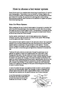
The purge eductor (FIGURE 16) is a liquid powered jet pump (ejector). Jet pumps have no moving parts and use a high pressure stream of liquid (solution from the solution pump discharge line) passing through a nozzle to cause a portion of a low pressure stream (condenser refrigerant vapor and non-condensables) coming into the side of the pump to combine with the nozzle stream. This causes a reduction in pressure at the low pressure inlet and induces the rest of the low pressure inlet substance to flow into the body of the pump. In the diffuser section of the pump some of the velocity of the combined liquid flow is converted back to pressure. The eductor outlet will be at a pressure between the high pressure inlet and the low pressure inlet (see FIGURE 16). Pressurized Solution Flow from Solution Pump Discharge Induced Flow of Saturated water Vapor containing NonCondensables from Condenser Nozzle
Low Pressure Area Created Around The Jet of Solution That is Forced Through the Eductor Nozzle
Solution Containing Non-Condensables to Gas Separator
Eductor outlet Should be 10°F (5.6°C) warmer than Solution Inlet when working Properly
ld05090d
FIGURE 16 - PURGE EDUCTOR VP10 VP2
FIGURE 15 - YIA PURGE TANK
PURGE EDUCTOR
VP4
ld1457c4
29
3
Purging and Non-condensables
FORM 155.21-OM1 (510)
GAS SEPARATOR The gas separator is where the non-condensables are removed from the solution flowing out of the purge eductor (FIGURE 16). Solution mixed with non-condensable gases flows into the side of the separator where it enters an annulus between the inner chamber and the outer wall of the separator. The swirling and overflowing action induced by the inner chamber causes the non-condensables to rise up and accumulate near the top of the separator. The solution outlet pipe extends down into the inner chamber where solution with no non-condensables is present. The non-condensables accumulating near the top of the gas separator pass upward through the noncondensable outlet pipe into the purge tank.
GAS SEPARAToR
Non-Condensables to Purge Tank
weak Solution Returns to Absorber
Level in outlet Pipe will Vary with Purge Tank Pressure
Swirling Action in outer Annulus and Spillover into Inner Chamber Separates NonCondensables from Solution
weak Solution with Entrained NonCondensables From Purge Eductor
FIGURE 17 - GAS SEPARATOR
ld05090
Valves Some special valves have been added to the YIA autopurge system. All of the valves are designed to be reliable and leak-free. There are several special purpose valves used, such as the check valve and the automatic purge valves. Please note all valves have been given a designation number for identification purposes.
VP1 This manual valve is used for initial purging of the unit at unit commissioning. When open it will pull noncondensables out of the absorber/evaporator shell from a higher location than VP4. It is connected in series just before valve VP4 on the purge tree end, both valves will need to be open for manual purging. Note: on larger units this valve maybe stand alone. VP2 This manual diaphragm valve is used to remove noncondensables from the purge tank. It must be always open when in the auto-purge mode. VP4 This valve is used to manually purge the absorber section of the unit. It is connected to the internal absorber purge header system located below the tube bundle. When open the purge pump will pull the non-condensables from the absorber. It is always in the closed position for auto-purging. 7SOL (Purge Tank Pressure Valve) This solenoid valve is only supplied on units with the auto-purge feature. The Optiview panel will control the opening and closing of this valve in auto or manual purge mode. It only opens when the pressure from PT3 is proven to be 15 mm Hg absolute or less. When this valve is open, non-condensables from the purge tank are allowed to be purged out. 8SOL (Purge Pump Pressure Valve) This motorized ball valve is only supplied on units with the auto-purge feature. The Optiview panel will control the opening and closing of this valve in auto or manual purge mode. After the purge pump is started and completed the warm up period, 8SOL will open. A 60 second timer is started to allow this valve to open completely. If the pressure as monitored at PT3 is not at or below 15 mmHg absolute after the 60 seconds has expired, an additional 60 timer will commence. If the pressure is still above 15 mmHg absolute after the second 60 seconds has expired, 8SOL will close and a purge pump failure will be displayed. 8SOL and 7SOL are connected in series in order for 8SOL to be open to purge the non-condensables from the purge tank.
The following is a description of each individual valve and its functional purpose. Not all valves may be used on some models.
30
JOHNSON CONTROLS
FORM 155.21-OM1 (510)
VP8 This check valve is located between the purge pump and oil trap. It is a flapper-type check valve which must be installed horizontally with the “hinge” marking up and the “free flow” arrow pointing towards the purge pump. Its purpose is to provide added protection from air entering if the purge valve were open during an unattended power failure situation. It works best at high pressure differentials. Note: this valve is a maintenance item and may malfunction with extended or severe usage. It is located so that it can be taken apart and cleaned with kerosene or similar degreaser. The stamped “hinge” hex end will unscrew (right handed threads) from the body of the valve to access the flapper assembly. Oil Separator The oil separator is located in the suction line of the purge pump. It is constructed so that oil from the vacuum pump cannot get drawn into the unit should a power failure occur during purging. The separator is sized to hold twice the volume of the purge pump oil charge. The oil separator also serves as a trap in the unlikely event that solution gets drawn into the purge piping and helps prevent contamination of the purge pump. Absolute Pressure Gauge This gauge is important for reading the very low pressure in the absorber section of the unit or the vacuum pump. The gauge is no longer a manometer type gauge that contains mercury. It is a dial type, non-mercury absolute gauge that will meet todays standards for prohibiting mercury in the work environments. The gauge reads in Torr, which is the same as mmHg absolute. However, due to the extreme sensitivity of this gauge, the uppermost range is 40 Torr. Unlike the manometer gauge, it will not read purge tank pressure. Care should be taken to prevent lithium bromide solution from contaminating the gauge. Contamination will cause inaccuracies in the pressure reading and may damage the internal working components. The gauge will ship loose for field installation in the purge tree. It is highly recommended to install an isolation valve between the gauge and the purge tree for when the gauge is not in use.
JOHNSON CONTROLS
Purging Frequency The purge tank evacuation frequency will be dependent on several factors such as unit size, operational parameters, running time, solution chemistry, and of course, leak tightness of the unit. Some units may only need to have their purge tank evacuated a few times per year. Others may require more frequent evacuation. Although very frequent purge tank evacuation is a matter of concern, a change in the frequency is also an indicator of a unit problem. For instance, a unit may routinely accumulate 80 mm Hg of pressure in the purge tank over 200 hours of operation (approximately one month). If, all of the sudden, the purge tank accumulates 80 mm Hg pressure in 100 hours of operation (approximately two weeks), there is a strong indication that either a leak is developing, or there is a problem with the solution chemistry, or both. Therefore, if a unit is manually purged, it is important to keep track of the purging history. If the unit is equipped with SmartPurge™, the micro processor keeps track of the purging frequency and alerts you if it has become excessive. When to purge the purge tank The old philosophy of purging an absorption unit was to have the equipment room operator manually purge the unit once per day, whether it was necessary or not. In addition to purging from the purge tank, most operators preferred to purge from the absorber with the purge pump for a given period of time. Although some users may still prefer this method, it should not be necessary, providing the unit is in good health. Since the YIA unit’s internal purge system is automatically and continuously (while the unit is operational) moving non-condensables from critical areas of the unit, such as the absorber or condenser to the purge tank, it is only necessary to monitor the purge tank pressure and evacuate it periodically. It should not be necessary to purge the absorber with the purge pump on a properly operating unit. Although the purge tank can adequately maintain 100 mm Hg pressure, autopurge will evacuate the tank if the pressure exceeds 80 mm Hg. The purge tank will be evacuated until the tank pressure is reduced to 30 mm Hg. It is recommended that units without autopurge be purged the same way.
31
3
Purge Pump Operation
FORM 155.21-OM1 (510)
VP10
PURGE TANK
PT4
VP2 VP4 VACUUM GAUGE PT3 VENT To ABSoRBER To ABSoRBER
7SoL VP1
NoN-CoND. FRoM ABSoRBER
8SoL
FRoM SoLUTIoN PUMP DISCHARGE
oIL TRAP VP8
VENT To ABSoRBER
VENT
TEST HoSE GAS BALLAST
PURGE PUMP
To SoLUTIoN PUMP SUCTIoN
GAS SEPARAToR
LD14575
FIGURE 18 - THE COMPLETE ISOflow PURGE SYSTEM 32
JOHNSON CONTROLS
FORM 155.21-OM1 (510)
section 4 – purge pump operation GENERAL As previously discussed, each machine is equipped with a vacuum pump (refer to FIGURE 19) which is designed to remove non-condensables from various areas of the machine. The following issues should be kept in mind whenever operating a YORK Vacuum Pump. Cleanliness Take every precaution to prevent foreign particles from entering the pump. A fine mesh screen is provided for this purpose in the intake passage of all YORK Vacuum Pumps. Types of Lubricants All YORK mechanical vacuum pumps are tested with DUOSEAL® oil and shipped with a full charge to prevent unnecessary contamination. DUOSEAL® oil has been especially prepared and is ideally suited for use in mechanical vacuum pumps because of its desirable viscosity, low vapor pressure, and chemical stability. The vacuum guarantee on all YORK vacuum pumps applies only when DUOSEAL® oil is used. Purge Pump Piping and Operating Valves The purge pump piping and valves, illustrated in FIGURE 15, is installed at the factory and can be used for several functions. During normal operation, both the gas ballast and the leak rate test valve must be open at all times. The Principle of Gas Ballast The Effects of Unwanted Vapor - Systems which contain undesirable vapors cause difficulty from both the standpoint of attaining desirable pressures, as well as contamination of the lubricating medium. A vapor is defined as the gaseous form of any substance which is usually a liquid or a solid. Refrigerant (water) and alcohol vapors are two of the most common vapors encountered in absorption chillers. When such vapors exist in a system, the vapors or mixtures of gas and vapor are subject to condensation within the pump. This precipitated liquid may dissolve or become emulsified with the oil. This emulsion is recirculated to the chambers of the pump where it is again volatized, causing increased pressure within the system. JOHNSON CONTROLS
oil Trap Bubble Test Hose
Leak Rate Test Valve (open)
Gas Ballast Valve (open)
Purge Pump oil Drain ld06051
FIGURE 19 - purge pump piping and valves - normal operation
4
The Presence and Removal of Condensate Condensation takes place particularly in the compression stroke of the second stage of a two-stage pump. The compression stroke is that portion of the cycle during which the gas drawn from the intake port is compressed to the pressure necessary to expel it past the exhaust valve. Condensation takes place when the ratio between the initial pressure and the end pressure of the compression is high, that is, when the mixture of vapor and gas drawn from the intake port is compressed from a low pressure to a high pressure. By adding air through the gas ballast valve to the mixture of vapor and gas being compressed, the pressure required for delivery past the exhaust valve is reached with a considerably smaller reduction of volume of the mixture. Depending upon the amount of air added, condensation of the vapor is either entirely avoided or substantially reduced. Oil Level Determination The amount of oil suitable for efficient and satisfactory performance should be determined after the pump has reached its operating temperature. Initially the pump should be filled with fresh oil while the pump is idle. Fill the pump through the pump discharge port until the oil level falls halfway up the oil level window. If after a short period of operation, the level should fall, it is likely the result of oil entering some of the interior pockets of the pump. If the oil level rises, this means oil has drained into the pump cavity while idle. To correct this shut off the pump, then drain oil down to proper level. 33
Purge Pump Operation If a gurgling sound occurs, additional oil may need to be added. Mechanical pumps will gurgle in varying degrees under four conditions of performance: (1) when operating at high pressure as in the beginning cycles of evacuation of the purge drum; (2) when the oil level in the pump reservoir is lower than required;
34
FORM 155.21-OM1 (510)
(3) when a large leak is present in the system; and (4) when the gas ballast is open. Best performance of a mechanical pump is generally obtained after sufficient time has been allowed for the pump to come to operating temperature.
JOHNSON CONTROLS
FORM 155.21-OM1 (510)
section 5 – purge pump MAINTENANCE Vacuum Problems Pressure Determinations A simple test for the condition of a mechanical pump is a determination of its ultimate pressure capability. This can be accomplished by attaching a gauge directly to the pump. The gauge may be any suitable type provided consideration is given to the limitations of the gauge being used. The pump must be capable of pulling a vacuum of at least 2 mmHg absolute. If the pressure is unusually high, the pump may be badly contaminated, low on oil, or malfunctioning. On the other hand, if the pressure is only slightly higher than the guaranteed pressure of the pump, an oil change may be all that is required. Oil Contamination The most common cause of a loss in efficiency in a mechanical pump is contamination of oil. It is caused by condensation of water and alcohol vapors and by foreign particles. The undesirable condensate emulsifies with the oil which is recirculated and subjected to re-evaporation during the normal cycle of pump activity, thus reducing the ultimate vacuum attainable. Some foreign particles and vapors may form sludges with the oil, impair sealing and lubrication and cause eventual seizure. Although the gas ballast valve is helpful in removing vapors, especially water, it is not equally effective on all foreign substances; therefore, periodic oil changes are necessary to maintain efficient operation. The required frequency of changes will vary with the particular system. The oil should be changed when it looks dirty, cloudy, milky, or when the pump is not capable of pulling below 2mmHg Abs. Oil Changes and Oil Level Draining the Pump An oil change is most easily accomplished when the pump is warm and the oil is less viscous. Use a clear plastic container large enough for the oil in the particular pump. Stop the pump, and open the drain valve. Thoroughly drain the pump by tipping the pump slightly, if this is possible. The small residue remaining in the pump may be forced out by handrotating the pump pulley with the exhaust port par-
JOHNSON CONTROLS
tially closed and the intake port open. Closing the exhaust port completely under these conditions will create excessive pressure at the drain valve which may cause the oil being drained to splatter. Flushing the Pump This procedure should be performed whenever the performance of the pump is poor and changing the oil didn’t correct this shortcoming. 1. Check the oil level. a. If the oil level is well above the fill mark, this can indicate the pump has ingested lithium bromide solution. Go to step 2. b. If the oil level is even with the fill mark and you do NOT suspect lithium bromide solu tion has been ingested accidentally by the pump, run the pump for 15 minutes and allow the pump oil to warm up before going to step 2. 2. Turn off the motor for the vacuum pump. Drain the oil into a clear plastic container. Look for water settling to the bottom of the container. In some cases, an emulsion of oil and water can be seen between the oil and the water. If water is noticed, perform steps 3 through 5 several times until the oil comes out clear.
The oil drained from the pump is from the oil case only. There may be water or other contaminants in the pumping mechanism. To be sure all contaminants have been removed, the pump mechanism needs to be flushed. 3. Make sure the belt guard is installed before proceeding further. Attach a short hose to the drain valve which runs into a clear plastic container. Secure the hose end in the container so that it does not blow around during the next step. 4. Flushing the pump is carried out by adding a cup of new DUOSEAL® oil through the exhaust (OUT) port while the pump is turned on for 15-20 seconds. While adding the pump oil, the exhaust (OUT) port is blocked by the palm of your hand. Look for water coming out of the drain hose. Turn off the pump.
35
5
Purge Pump Operation 5. Repeat step 4 until only clean oil comes out of the drain hose. 6. Fill the pump (through the exhaust port) with 2.25 quarts of DUOSEAL® vacuum pump oil. 7. Plug the intake (IN) port with a rubber stopper. Turn the pump on and run the pump for 10 minutes. Close the gas ballast valve. Refilling the Pump Refill the pump by pouring new DUOSEAL® oil into the exhaust port. Fill to the indicated level and start the pump with the intake closed. A gurgling noise is normal when high pressure air is drawn through the pump. It should disappear quickly as the pressure within the pump is reduced. If gurgling continues (with gas ballast closed), add sufficient additional oil through the exhaust port until gurgling ceases. Shaft Seal Replacement To replace the shaft seal of a pump, drain the oil and remove the pump pulley and key. Remove the screws securing the old seal and pry it loose with a screwdriver or similar wedge, being careful not to mar the surface of the pump body against which the seal fits. Discard the seal and its gasket, inspect all surfaces and repair any damages with a fine abrasive stone. Wipe all sealing areas clean and place a film of DUOSEAL® oil on both the shaft and the inside bore of the new shaft seal. Using a new gasket, carefully slide the new seal into position and center it on the shaft. It is not necessary to apply any sealant to the gasket. Tighten the mounting screws uniformly and refill the pump with DUOSEAL® oil. Follow instructions included in repair kit. Repairing Oil Leaks Location, Cause and Effect Oil leaks may develop wherever two mating faces are sealed with a gasket. Such seams may fail as the result of deterioration of the gasket material, loosening of the screws caused by temperature variations, or improper care as the result of previous reassembly. Typical gasketed seams in a mechanical pump are located at the oil level window, the shaft seal, the oil drain and the mating faces of such mechanical surfaces as the intake chamber cover. The importance of a gasketed seam is determined principally by its function. If it is a vacuum seal, the ultimate performance of the pump is dependent upon it. If it is an oil seal, the pump may be operated satisfactorily for some time 36
FORM 155.21-OM1 (510)
without loss of function. Eventually, of course, a great loss of oil may cause harmful damage. Repairing Technique An oil seam may be sealed by any of several methods. When an O-ring is employed, the surfaces of the O-ring and its groove should be wiped clean. If the O-ring is not badly deformed or scratched, it may be reused by sealing with a slight film of vacuum oil or vacuum grease. Thin composition gaskets are generally used for large irregularly shaped areas. A replacement joint of this type should be thoroughly cleaned of all previous gasket material and the mating surfaces cleaned of any nicks. Drive Problems
When troubleshooting drive problems or checking belt tension, always shutoff and lock out power at the main disconnect switch. If for any reason the pump will not operate, turn off and lock out the power at the main circuit breaker or disconnect. Check the overload assembly and electrical connections. Remove the guard cover followed by the belt. Re-establish power to the pump. If the motor operates properly try hand-rotating the pump in the proper direction with the pump intake port open. If both turn freely, then replace the belt and check the belt tension. The tension should be sufficient to drive the pump without visible slippage. Any greater tension will cause noise and possible damage to the bearings of both the motor and pump. Make certain that both pulley grooves are clean and free from oil. The pulleys must be fastened securely on their respective shafts, and in parallel alignment. Re-install the belt guard and check for proper operation and amperage. Replace or re-build any defective components.
JOHNSON CONTROLS
FORM 155.21-OM1 (510)
GAS BALLAST PoRT 1/4" NPT FEMALE CoNNECTIoN
ld05105a
1-13/16" INTAKE NIPPLE, ACCEPTS 5/8" To 3/4" ID HoSE
3/4 - 20 THREAD
1-20 THREAD
5
STD MoToR, 1/2 HP 12-5/8"
41-0669 MTG. STRIP 2-01-0312 BoLT 2-61-3100 wASHER
9"
4"
3-1/2"
2"
1-7/8"
41-0929 BUMPER 2-02-5708 SCREw
7-3/16"
4-7/8"
2-01-0316 BoLT 41-2363 wASHER 2-35-3800 NUT
10-1/4"
ld05105B
SPECIFICATIONS: Free- Air Displacement, L/M . . . . . . . . . . . . . . . . . . . . . . . . . . . . . . . . . . . . . . . 160 CFM . . . . . . . . . . . . . . . . . . . . . . . . . . . . . . . . . . . . . . . . . . . . . . . 5.6 Guaranteed Partial Pressure Blankoff, millitorr . . . . . . . . . . . . . . . . . . . . . . . . . . . . . . . . . . . . . . . . . 0.1 Pump Rotational Speed, RPM . . . . . . . . . . . . . . . . . . . . . . . . . . . . . . . . . . . . . 525 Number of Stages . . . . . . . . . . . . . . . . . . . . . . . . . . . . . . . . . . . . . . . . . . . . . . . . . 2 Oil Capacity, qts . . . . . . . . . . . . . . . . . . . . . . . . . . . . . . . . . . . . . . . . . . . . . . . 2-1/4 Net Weight, Pump Only, lbs . . . . . . . . . . . . . . . . . . . . . . . . . . . . . . . . . . . . . . . . 82 Net Weight, Mounted Pump, lbs . . . . . . . . . . . . . . . . . . . . . . . . . . . . . . . . . . . . 112 Shipping Weight, Mounted Pump, lbs . . . . . . . . . . . . . . . . . . . . . . . . . . . . . . . . 125 FIGURE 20 - MODEL 1402 VACUUM PUMP FOR YORK JOHNSON CONTROLS
37
Buffalo Pumps
FORM 155.21-OM1 (510)
THIS PAGE INTENTIONALLY LEFT BLANK
38
JOHNSON CONTROLS
FORM 155.21-OM1 (510)
section 6 – buffalo pumps Introduction The Buffalo pumps used on YORK IsoFlowTM chillers are single suction, single-stage, hermetically sealed centrifugal pumps designed for zero leakage, Totally Closed Liquid Cooled (TCLC) applications. The pumps employ a unique spring-loaded conical bearing design that allows for long life between overhauls. The pump bearings are cooled and lubricated by the pumping fluid (refrigerant water or lithium bromide solution). The pumping liquid also carries away heat generated by the motor.
Do not run the pump dry. Even momentary operation without the pump and motor casing filled with liquid will damage pump bearings. FIGURE 21 shows a cutaway view of a single-ended pump. The arrows indicates the cooling circuit through the pump. Troubleshooting Pump Tripping on Overloads Check voltage supply on all three phases to be sure it is correct for the pump motor in question. Check overload for proper amperage setting (Pump Motor FLA), loose wires or poor connections that generate heat and trip the overload. If no problems are found, shut off all power to the unit, and lock-out / tag-out all disconnects. Check the motor connections to be sure the pump is wired correctly. Using a megohm meter, check the pump motor windings for shorts or grounds. If motor problems are found, motor replacement will be necessary (Contact your local York Factory Service office for details). If no problems are found during this procedure, reconnect the motor. Apply power to the unit and run the pump while watching the operating amps. If high amps are encountered, the problem may be mechanical, such as bearing seizure. Pump inspection will be necessary. If the overload continues to trip, but the motor amperage is within the allowable range, the overload is defective.
JOHNSON CONTROLS
Pump Tripping on Thermal Protection If the winding temperature thermostat is tripping the pump, allow the thermostat to reset. Exercise caution as the motor housing skin temperature may be in excess of 300°F (148.9°C) when the winding temperature thermostat trips. Although rare, if the thermostat will not reset in a reasonable period of time, it may be defective. If this is the case, temporarily bypass the thermostat and run the pump. Check the motor housing temperature with an infrared thermometer. The average outside skin temperature of a solution pump motor housing is 190°F (87.8°C) at stable operating conditions [100°F (37.8°C) suction temperature]. Refrigerant pumps run cooler than this. Check to be sure that the pump is not running dry periodically or that either the suction/discharge isolation valves are closed. Check to see that the pump is not pumping abnormally high-temperature liquid for some reason. If no problems related to flow through the pump are found, the internal coolant passages may be blocked. Pump disassembly will be required. Contact your local YORK Factory Service office for details. Unusual Noise/Vibration Pumps will make some noise during normal operation. If pump is experiencing cavitation, the noise and vibration will be more severe. Abnormal sounds and vibration may be due to foreign material trapped in the coolant circuit and rubbing between the stator and rotor. Noise may also be a result of extreme bearing wear. Pump disassembly is required. Pump Overhaul The expected time span between Buffalo Pump overhauls on a properly maintained IsoFlowTM unit should be between 50,000 and 60,000 hours. Pumps installed on units running with high amounts of suspended solids or high amounts of dissolved copper in the solution will suffer shorter lives. It is therefore recommended to install a solution filtration kit on the unit to remove the suspended solids and/or perform a copper removal procedure as indicated on the solution chemistry report. Contact your local York Factory Service office for details.
39
6
FORM 155.21-OM1 (510)
ld05106A
Steam and Water Quality Control
FIGURE 21 - flow of refrigerant water or lithium bromide through pump 40
JOHNSON CONTROLS
FORM 155.21-OM1 (510)
section 7 – STEAM and water quality control WaterSide general Information The absorber/condenser and evaporator water must be free of corrosive elements or inhibited to prevent attack of the waterside tubing. Impurities and dissolved solids can cause scaling that reduces heat exchanger efficiency and causes corrosion of tubes. Corrosion, in turn, can result in more serious problems, such as metal wastage and contamination of the solution and refrigerant if through-wall pitting occurs. For additional various water qualities see Chiller Materials Application Guide YORK Form 160.00-AD5. YORK IsoFlowTM Absorption Chillers can only deliver design output and efficiency if they are properly operated and maintained. One of the most important elements of proper maintenance is the cleanliness of the tubes to prevent fouling, scaling and corrosion during daily operations and shutdowns. It is the responsibility of the owner (operator) of this equipment to engage the services of an experienced and reputable water treatment specialist for both the initial charging of the system and its continuous monitoring and treatment. Improperly treated or maintained water will result in decreased efficiency, high operating costs and premature failure due to waterside corrosion. For water treatment programs to be acceptable, they must protect all exposed metal (i.e., carbon steel, copper and brass) from corrosive attack. The use of corrosion inhibitors must be effective at low concentrations, must not cause deposits on the metal surfaces, and must remain effective under a broad range of pH, temperature, water quality and heat flux. Furthermore, the inhibitor package must prevent scale formation and disperse deposits, while having a minimal environmental impact when discharged. Water samples should be collected and analyzed on at least a monthly basis by the water treatment specialist. A quarterly review with the treatment supplier should address the conditions of the water systems and develop action plans based on these analyses. A third party water consulting company can help oversee the water treatment programs in order to properly protect the physical plant and avoid costly downtime.
JOHNSON CONTROLS
It is equally important that the owner (operator) of the equipment performs tube cleaning and inspection of the absorber, condenser and evaporator waterside tubes at the frequencies recommended in the Tube Bundle Section of the "Preventive Maintenance Schedule" located in this manual. In addition to periodic cleaning with tube brushes, tubes must be inspected for wear and corrosion. Tube failures usually occur due to corrosion, erosion, and fatigue due to thermal stress. Eddy current analysis and visual inspection by boroscope of all tubes are invaluable preventative maintenance methods. These provide a quick method of determining waterside tube condition at a reasonable cost. Steam/Condensate or hot water Quality YORK IsoFlow™ units use corrosion resistant CuNi tubes in the generator. As with the waterside of the system, it is the responsibility of the owner (operator) of this equipment to engage the services of an experienced and reputable steam/condensate or hot water treatment specialist for both the initial charging of the system and its continuous monitoring and treatment. Improperly treated or maintained steam/condensate or hot water will result in decreased efficiency, high operating costs and premature failure due to steam/condensate or hot water side corrosion. Steam/Condensate or hot water samples should be collected and analyzed on at least a monthly basis by the treatment specialist. A quarterly review with the treatment supplier should address the conditions of the steam systems and develop action plans based on these analyses. A third party consulting company can help oversee the treatment programs in order to properly protect the physical plant and avoid costly downtime.
41
7
Unit Operating Procedures It is equally important that the owner (operator) of the equipment performs an inspection of the generator tubes at the frequencies recommended in the Tube Bundle Section of the "Preventive Maintenance Schedule" located in this manual. In addition to periodic cleaning with tube brushes, tubes must be inspected for wear and corrosion. Tube failures usually occur due to corrosion, erosion, and fatigue due to thermal stress. Eddy current analysis and visual inspection by boroscope of all tubes are invaluable preventative maintenance methods. These provide a quick method of determining steam generator tube condition at a reasonable cost. Your local YORK Service Representative will be more than happy to supply any or all of these services. Tube Cleaning If during an inspection, scale is identified in any of the tube bundles, it will be necessary to remove this scale to prevent operational and or corrosion problems.
42
FORM 155.21-OM1 (510)
A build-up of scale on the tubes can cause a wide range of problems including:
• Reduced chilling capacity • High solution concentration • Crystallization • Pitting and corrosion of tubes • Reduced efficiency
The first step in trying to clean scales from tubes is to brush clean them. Only soft nylon brushes should be used, as damage to the copper or CuNi tubes will result if harder brushes (such as steel) are used. If the brush cleaning is unsuccessful in removing all the scale from the tubes, it will be necessary to chemically clean them. An experienced and reputable contractor should be consulted. If the chemical cleaning is not performed properly, extensive tube damage may result.
JOHNSON CONTROLS
FORM 155.21-OM1 (510)
section 8 – unit operating procedures general For complete details on installation and how to set-up the companion parameters that control the YIA absorption units refer to Form 155.21-N1.
It is recommended that Manual/Off/ Automatic switches be used for control of the condensing water pump, the chilled water pump, and the tower fan motor. However, the chilled water pump and the condensing water pump must always be operating when the unit is in operation, and are thus preferred in the "Automatic" position. This is necessary to provide proper dilution of the solution, thus protecting against crystallization during shutdown, and to avoid freezing up the evaporator tubes during unit operation, including the dilution cycle operation during which refrigeration effect still occurs.
2. Refer to the chart in FIGURE 22 to compare the saturation pressure within the unit to the equivalent plant room temperature. If the measured internal unit pressure is within the shaded area of the chart, the start-up may continue. If not, purge the unit until the internal unit pressure reaches the shaded area of the chart. 3. Open the main shut-off valves in condensing water, chilled water, and steam or hot water supply lines to the system. 4. Close all disconnect switches to the control panel, the cooling water pump, chilled water pump, and tower fans. 5. Place the condensing water pump, chilled water pump, and tower fan switches in the "Automatic" position. (If manual operation is required for special considerations, refer to the NOTE under General). 50
This start-up covers units that have previously been started.
See Form 155.21-O1, “Control Panel Operation Manual” for detailed instruction on how to operate the OptiView control panel. 1. If the chiller has been idle for a long period of time, such as at the first start-up of the cooling season, it will be necessary to check the internal pressure of the unit to ensure a smooth start-up and possibily perform a purge from the absorber section.
PRESSURE IN mm Hg Abs.
start-up (Normal)
10
8 1
40
60
80
100
120
PLANT RooM TEMPERATURE °F ld06021
FIGURE 22 - acceptable internal unit pressures
JOHNSON CONTROLS
43
Unit Operating Procedures operating data General A complete set of data on operating temperatures and pressures should be recorded for the unit regularly. The purpose is to permit early recognition of an abnormal condition or trend that requires corrective maintenance, before serious damage occurs to the unit. Daily observation of the unit is useful to disclose any sudden changes. Record these changes on FORM 155.16-F2. All measurements that are recorded should be taken as simultaneously as possible with a steady load and a steady cooling tower water temperature, near the design conditions. A progressive gradual deterioration in unit performance is an indication that scaling is occurring, that there is a gradual buildup of inerts or that there is a malfunction of controls. It is mandatory that all performance analyses be based on date, and taken on units that are free of leaks. Otherwise, the lithium bromide concentrations and the steam pressure and steam flow requirements for a given load, as well as a complete set of operating temperatures, will be abnormal. A thorough check of system performance, including sampling of the unit fluids, requires the services of a Johnson Controls Field Service Representative. He will take samples of the refrigerant, the lithium bromide charge, and the cooling water, as well as a complete set of operating data. He can assist in a complete performance analysis and report on the condition of the unit. Samples can be analyzed and a complete report obtained on the chemical content and pH levels. The investment by the customer in the cost of these services is nominal compared to the cost of the unit and the ultimate cost of repairs or increased operating costs, should the unit be inadequately maintained. Inadvertent introduction of air into the unit by the operator or the existence of leaks are to be avoided at all times to ensure a long life of the unit. The proper method of taking samples is straight forward but requires special training so that conclusions reached concerning the condition of the unit, the solution chemistry and the cooling water are valid.
44
FORM 155.21-OM1 (510)
For greatest accuracy of the data taken on operating units, calibrated 1/5°F increment thermometers should be used, particularly for measuring temperatures of chilled water and cooling water. Calibrated test type pressure gauges and manometers also contribute to the attainment of accurate data. Accurate flow meters for water and steam condensate flow (with a subcooler) complete the instrumentation requirements for the attainment of an accurate heat balance. This instrumentation is not normally available in the field. However, it can be obtained by special arrangements. Nevertheless, a measure of the trend of system performance can be obtained by the systematic measurement of data taken with instrumentation normally available in the field. In all cases, however, any analysis is only as good as the degree of accuracy of the data taken. A steady state of operating conditions with all readings taken as simultaneously as possible, assists in obtaining valid data. All thermometers and pressure measuring devices should be calibrated so that readings are corrected to the true values. Insulation placed around the pipe and the outside well will improve the accuracy and validity of readings. With the assumption that all data taken are accurate and valid, the following method of analysis for system performance is recommended. Performance Data and Calculations Refer to the sample operating data sheet in FIGURE 23. This data is simulated by a computer for a YIA6C4 unit with nominal passes. The assumed operating condition is 80% of the design load rating with assumed fouling factors of .0005, .001 and .0015 in the absorber and condenser, but with .0005 in the evaporator tubes. The effect of fouling on all readings is readily apparent. This data also assumes that the 2-Ethyl-1-Hexanol additive is present in the unit at the proper concentration to promote optimum shell side coefficients of heat transfer. This additive is charged into the unit upon initial start-up, and rarely does more Hexanol have to be added. The effect of Hexanol additive on unit performance appears later in this section. The design load rating for the YIA-6C4 unit used for the data simulation is as follows:
JOHNSON CONTROLS
FORM 155.21-OM1 (510)
100% Design Load Condenser Water Flow Entering Condenser Water Temp Chilled Water Flow Chilled Water Range
517.9 Tons 1870 GPM 85°F 1243 GPM 54°F to 44°F
Passes - Chiller/Condenser/Absorber 2/1/1 Fouling Factor for Absorber, Condenser and Evaporator .0005 Steam Pressure at Generator 9.2 PSIG Steam Flow 9478 lb/hr
Valve Inlet Steam Pressure 12PSIG = 299°F Normal Installation Ambient Pressure 29.5" Hg (14.5 PSIA) Steam Source 15PSIG@300°F
Assume steam condensate is flashed at atmospheric pressure before it is weighed for test data purposes.
8
LD04771
FIGURE 23 - OPERATING DATA SHEET JOHNSON CONTROLS
45
PTX Chart
FORM 155.21-OM1 (510)
THIS PAGE INTENTIONALLY LEFT BLANK
46
JOHNSON CONTROLS
FORM 155.21-OM1 (510)
section 9 – ptx chart READING THE PTX CHART
CRYSTALLIZATION
The PTX chart (Pressure, Temperature, and Concentration chart) shown in FIGURE 24 is an invaluable tool when it comes to absorption cooling. It can be used for almost every kind of troubleshooting situation, plotting solution cycles through each heat exchanger, and determining if air is within the system.
All absorption chillers that use lithium bromide and water as the solution/refrigerant pair are subject to crystallization. This is due to the fact that some areas of the unit operate with solution liquid concentration levels that are only possible at higher than the normal ambient temperature surrounding the unit. For example, the solution concentration in the generator of a single stage absorption unit is typically 64.3% lithium bromide by weight. Referring to FIGURE 24, 64.3% solution will begin to crystallize at 110°F (43.3°C). Since the solution temperature in the generator normally is higher than 200°F (93.3°C) at most load conditions, no crystallization will occur as long as the higher solution temperatures are maintained. Special measures do have to be taken before the unit is shut down so that the solution is sufficiently diluted in all areas of the unit to prevent crystallization during the off cycle, since the solution temperature will eventually equal the surrounding ambient temperature.
However, for this exercise the PTX chart will be explained only for determining the concentration of solution samples.
Taking solution samples must only be done by a trained and qualified Johnson Controls Field Service Representative. Determining the Solution Concentration The PTX chart (FIGURE 24) shows pressure in mm Hg. absolute (horizontal lines), temperature in degrees fahrenheit (vertical lines), and Solution Concentration in percentages (diagonal lines). The amount of water necessary to make the compound turn into a fluid is represented by the area to the left of the crystallization zone on the PTX Chart, at the corresponding temperature. The "Crystallization Area" is the right half of the chart. In reading the PTX chart, two of three pieces of information are required. With these two pieces of data the third data point can be obtained. The temperature is the easiest to obtain and the pressure can be obtained via the unit gauges. Use caution when using the unit mounted vacuum gauge for checking the internal unit pressure – do NOT under any circumstances let air into the unit when checking the pressure. See the Purging section of this manual for the correct method to check the unit pressures. Looking at the PTX chart, follow the vertical temperature line and the horizontal pressure line to where the two intersect. The closest diagonal line to this intersection would be the correct solution concentration. As the concentration of lithium bromide increases, reducing water content, the solution becomes more viscous. When all water is removed the solution returns back to its natural state as a solid. JOHNSON CONTROLS
All units employ some sort of dilution cycle, which fulfills this requirement. As long as the unit is allowed to dilute itself during an orderly shutdown sequence, the unit should be able to sit idle at fairly low plant room ambient temperatures for extended periods of time without any threat of crystallization. Typically, after a dilution cycle, the average solution concentration within the chiller will be below 45% lithium bromide by weight. Although the crystallization line on FIGURE 24 does not extend that far, it can be seen that the solution at 45% concentration will have no tendency to crystallize at normal ambient temperatures. Why Does Crystallization Occur? Probably the most common reason for crystallization is due to power failures. If a chiller is running at full load and power is interrupted for a sufficient length of time, the concentrated solution in the high side of the unit will eventually cool down. Since no dilution cycle was performed, the solution concentration in some areas of the unit may still be relatively high. If the temperature of this concentrated solution is allowed to fall low enough, the solution will reach its crystallization point. Plant room temperature, insulation quality and the solution concentration all play a part in the determination of how long it will take before the unit will crystallize. 47
9
48
FIGURE 24 - PTX CHART
°F + 40 1.8
–
40
°F = (°C+ 40) x 1.8 – 40
90
100
110
120
130
140
% 55
150
160
% 60
170
180
% 65
190
200
210
% 50
250
220
230
240
250
cRYSTALLIZATION AREA
240
260
260
270
% 55
270
280
280
290
% 60
290
300
300
310
% 65
310
320
320
330
330
340
340
% 70
60
70
80
90
100
110
120
130
140
150
160
170
180
190
200
210
220
350
8
SOLUTION TEmPERATURE F
30 350
30 40 80
% 50
% 45
230
4.2
% 45
% 40
220
40
70
% 40
170
200
210
220
210
40
60
100
110
120
130
160
F
180
190
900
200
6
50
80
90
80
E UR AT R PE m TE 150
300
T AN ER G 140 I FR RE
g h
400
500
600
700
800
995.5
50
60
70
50
70
100 90
N IO AT R 150 U T SA
m m E R SU ES 200 PR
TM
50
10
15
20
30
40
60
1 ton refrigeration (12,000 Btu/hr) = 3.52 kw
1 inch = 25.4 mm
1 U.S. gallon = 3.785 liters
1 liter = .2641 U.S. gal = 1.057 U.S. quarts
1 lb = .4536 Kg = 453.6 gms
1 ft H2o = .433 psi
1 psi = 2.036 in Hg = 51.7 mm Hg = 2.31 ft H2o
1 in Hg = 25.4 mm Hg = .491 psi
1 mm Hg = 1000 microns = 0.3937 inch Hg = .01934 psi
1 atm (atmosphere at sea level) = 14.696 psia = 0 psig = 760 mmHg = 29.92 in Hg
°C =
To convert °C (Centigrade) to °F (Fahrenheit) or °F to °C:
Useful Conversion Formulas
Absorption Liquid Chillers
TM
ParaFlow and IsoFlow
FORM 155.17-PTX1 (609)
PTX Chart FORM 155.21-OM1 (510)
LD14221
JOHNSON CONTROLS
FORM 155.21-OM1 (510)
FORM 155.17-PTX1 (609)
SPEcIFIc GRAVITY - cONcENTRATION TABLES AQUEOUS LiBr SOLUTIONS Refrigerant Table (%LiBr by Weight) Temperature F S.G. 1.00 1.01 1.02 1.03 1.04 1.05
40 –– 0.98 2.43 3.84 5.22 6.57
45 –– 1.08 2.52 3.94 5.32 6.67
50 –– 1.17 2.62 4.03 5.42 6.77
55 –– 1.27 2.72 4.13 5.51 6.87
60 –– 1.37 2.82 4.23 5.61 6.96
65 –– 1.47 2.91 4.33 5.71 7.06
70 0.08 1.56 3.01 4.42 5.81 7.16
75 0.18 1.66 3.11 4.52 5.90 7.26
80 0.28 1.76 3.20 4.62 6.00 7.35
85 0.37 1.85 3.30 4.72 6.10 7.45
90 0.47 1.95 3.40 4.81 6.19 7.55
95 0.57 2.05 3.50 4.91 6.29 7.64
100 0.67 2.15 3.59 5.01 6.39 7.74
Solution Tables Temperature F S.G 1.350 1.360 1.370 1.380 1.390 1.400 1.410 1.420 1.430 1.440 1.450 1.460 1.470 1.480 1.490 1.500 1.510 1.520 1.530 1.540 1.550 1.560 1.570 1.580 1.590 1.600 1.610 1.620 1.630 1.640 1.650 1.660 1.670 1.680 1.690 1.700 1.710 1.720 1.730 1.740 1.750 1.760 1.770 1.780 1.790 1.800 1.810 1.820 1.830 1.840 1.850
60 37.27 38.03 38.78 39.52 40.25 40.97 41.69 42.39 43.10 43.79 44.47 45.15 45.82 46.48 47.13 47.78 48.42 49.05 49.67 50.29 50.89 51.49 52.09 52.67 53.25 53.81 54.37 54.93 55.47 56.01 56.54 57.06 57.58 58.08 58.58 59.07 59.55
70 37.5 38.26 39.01 39.75 40.48 41.20 41.91 42.62 43.32 44.01 44.69 45.37 46.03 46.69 47.35 47.99 48.63 49.26 49.88 50.49 51.10 51.69 52.28 52.87 53.44 54.01 54.57 55.12 55.66 56.20 56.72 57.25 57.76 58.26 58.76 59.25 59.73 60.20 60.67 61.13
80 37.75 38.50 39.24 39.98 40.70 41.42 42.14 42.84 43.54 44.23 44.91 45.58 46.25 46.91 47.56 48.20 48.84 49.46 50.08 50.69 51.30 51.89 52.48 53.06 53.64 54.20 54.76 55.31 55.85 56.38 56.91 57.43 57.94 58.44 58.94 59.42 59.90 60.38 60.84 61.30 61.74
90 37.98 38.73 39.47 40.20 40.93 41.65 42.36 43.06 43.76 44.45 45.13 45.80 46.46 47.12 47.77 48.41 49.04 49.67 50.28 50.89 51.50 52.09 52.68 53.26 53.83 54.39 54.95 55.49 56.03 56.57 57.09 57.61 58.12 58.62 59.11 59.60 60.08 60.55 61.01 61.46 61.91 62.35 62.78
100 38.21 38.96 39.70 40.43 41.16 41.87 42.58 43.28 43.98 44.66 45.34 46.01 46.67 47.33 47.97 48.61 49.25 49.87 50.49 51.09 51.69 52.29 52.87 53.45 54.02 54.58 55.13 55.68 56.22 56.75 57.27 57.79 58.29 58.79 59.29 59.77 60.25 60.72 61.18 61.63 62.08 62.51 62.94 63.37 63.78
110 38.44 39.19 39.93 40.66 41.38 42.09 42.80 43.50 44.19 44.88 45.55 46.22 46.88 47.54 48.18 48.82 49.45 50.07 50.68 51.29 51.89 52.48 53.06 53.64 54.21 54.77 55.32 55.86 56.40 56.93 57.45 57.97 58.47 58.97 59.46 59.94 60.42 60.88 61.34 61.80 62.24 62.68 63.10 63.52 63.94 64.34
cRYSTALLIZATION AREA
120 38.67 39.42 40.15 40.88 41.60 42.31 43.02 43.72 44.41 45.09 45.76 46.43 47.09 47.74 48.38 49.02 49.65 50.27 50.88 51.49 52.08 52.67 53.25 53.83 54.39 54.95 55.50 56.05 56.58 57.11 57.63 58.14 58.65 59.14 59.63 60.11 60.59 61.05 61.51 61.96 62.40 62.84 63.26 63.68 64.09 64.50 64.89
130 38.90 39.64 40.38 41.10 41.82 42.53 43.24 43.93 44.62 45.30 45.97 46.6 47.30 47.95 48.59 49.22 49.85 50.47 51.08 51.68 52.28 52.86 53.44 54.02 54.58 55.14 55.69 56.23 56.76 57.29 57.81 58.32 58.82 59.31 59.80 60.28 60.75 61.22 61.67 62.12 62.56 63.00 63.42 63.84 64.25 64.65 65.05 65.43
140 39.13 39.87 40.60 41.32 42.04 42.75 43.45 44.15 44.83 45.51 46.18 446.85 47.50 48.15 48.79 49.42 50.05 50.66 51.27 51.87 52.47 53.05 53.6 54.20 54.77 55.32 55.87 56.41 56.94 57.46 57.98 58.49 58.99 59.48 59.97 60.45 60.92 61.38 61.84 62.28 62.72 63.16 63.58 64.00 64.40 64.81 65.20 65.58 65.96
150 39.35 40.09 40.82 41.54 42.26 42.97 43.67 44.36 45.04 45.72 46.39 47.05 47.70 48.35 48.99 49.62 50.24 50.86 51.46 52.06 52.66 53.24 353.82 54.39 54.95 55.50 56.05 56.59 57.12 57.64 58.15 58.66 59.16 59.65 60.14 60.61 61.08 61.54 62.00 62.44 62.88 63.31 63.74 64.15 64.56 64.96 65.35 65.73 66.11 66.48
FIGURE 25 - SPECIFIC GRAVITY - CONCENTRATION JOHNSON CONTROLS
160 39.58 40.31 41.04 41.76 42.48 43.18 43.88 44.57 45.25 45.93 46.59 47.25 47.91 48.55 49.19 49.82 50.44 51.05 51.66 52.25 52.84 53.43 54.00 54.57 55.13 55.68 56.23 56.76 57.29 57.81 58.33 58.83 59.33 59.82 60.30 60.78 61.25 61.71 62.16 62.60 63.04 63.47 63.89 64.30 64.71 65.11 65.50 65.88 66.26 66.63 66.99
170 39.80 40.53 41.26 41.98 42.69 43.39 44.09 44.78 45.46 46.13 46.80 47.46 48.11 48.75 49.38 50.01 50.63 51.24 51.84 52.44 53.03 53.61 54.18 54.75 55.31 55.86 56.40 56.94 57.46 57.98 58.50 59.00 59.50 59.99 60.47 60.94 61.41 61.87 62.32 62.76 63.20 63.62 64.04 64.46 64.86 65.26 65.65 66.03 66.41 66.77 67.13
180 40.02 40.75 41.48 42.20 42.90 43.61 44.30 44.99 45.67 46.34 47.00 47.66 48.30 48.94 49.58 50.20 50.82 51.43 52.03 52.63 53.21 53.79 54.37 54.93 55.49 56.04 56.58 57.11 57.64 58.15 58.67 59.17 59.66 60.15 60.63 61.10 61.57 62.03 62.48 62.92 63.35 63.78 64.20 64.61 65.01 65.41 65.80 66.18 66.55 66.92 67.27
190 40.24 40.97 41.69 42.41 43.12 43.82 44.51 45.19 45.87 46.54 47.20 47.85 48.50 49.14 49.77 50.39 51.01 51.62 52.22 52.81 53.40 53.97 54.55 55.11 55.66 56.21 56.75 57.28 57.81 58.32 58.83 59.33 59.83 60.31 60.79 61.26 61.73 62.18 62.63 63.07 63.51 63.93 64.35 64.76 65.16 65.56 65.94 66.32 66.70 67.06 67.42
200 40.46 41.19 41.91 42.62 43.33 44.03 44.72 45.40 46.07 46.74 47.40 48.05 48.70 49.33 49.96 50.58 51.20 51.80 52.40 52.99 53.58 54.15 54.72 55.28 55.84 56.38 56.92 57.45 57.97 58.49 59.00 59.50 59.99 60.48 60.95 61.42 61.89 62.34 62.79 63.23 63.66 64.08 64.50 64.91 65.31 65.70 66.09 66.47 66.84 67.20 67.56
210 40.68 41.41 42.12 42.83 43.54 44.23 44.92 45.60 46.27 46.94 47.60 48.25 48.89 49.52 50.15 50.77 51.38 51.99 52.59 53.18 53.76 54.33 54.90 55.46 56.01 56.55 57.09 57.62 58.14 58.66 59.16 59.66 60.15 60.64 61.11 61.58 62.04 62.50 62.94 63.38 63.81 64.23 64.65 65.06 65.46 65.85 66.24 66.61 66.98 67.35 67.70
220 40.90 41.62 42.34 43.04 43.75 44.44 45.12 45.80 46.47 47.14 47.79 48.44 49.08 49.71 50.34 50.96 51.57 52.17 52.77 53.36 53.94 54.51 55.07 55.63 56.18 56.72 57.26 57.79 58.31 58.82 59.32 59.82 60.31 60.79 61.27 61.74 62.20 62.65 63.09 63.53 63.96 64.38 64.80 65.21 65.60 66.00 66.38 66.76 67.13 67.49 67.84
230 41.11 41.83 42.55 43.25 43.95 44.64 45.33 46.00 46.67 47.33 47.99 48.63 49.27 49.90 50.53 51.14 51.75 52.35 52.95 53.53 54.11 54.68 55.25 55.80 56.35 56.89 57.43 57.95 58.47 58.98 59.49 59.98 60.47 60.95 61.43 61.89 62.35 62.80 63.25 63.68 64.11 64.53 64.95 65.35 65.75 66.14 66.52 66.90 67.27 67.63 67.98
240 41.33 42.05 42.76 43.46 44.16 44.85 45.53 46.20 46.87 47.53 48.18 48.82 49.46 50.09 50.71 51.33 51.93 52.53 53.12 53.71 54.29 54.86 55.42 55.97 56.52 57.06 57.59 58.12 58.63 59.14 59.65 60.14 60.63 61.11 61.58 62.05 62.50 62.95 63.40 63.83 64.26 64.68 65.09 65.50 65.89 66.28 66.67 67.04 67.41 67.77 68.12
9
LD14221
49
PTX Chart Power failures result in the unit pumps stopping completely. Without the pumps inducing flow through the various sections of the unit, concentrated solution becomes trapped in the generator section and the solutionto-solution heat exchanger. If this concentrated solution is allowed to cool down to a low enough temperature, it may turn to a slushy liquid and eventually to a solid substance. The potential for a YORK IsoFlowTM Chiller to crystallize during a power interruption is directly related to the following: 1. The concentration of the solution in the solution heat exchanger is very important. The higher the concentration at the time of power failure, the more likely the unit is to crystallize. a. The higher the load, the higher the concentration. b. A unit with dirty tubes or non-condensables will be more susceptible due to higher concentrations in the solution heat exchanger. c. Overfiring the unit will tend to over concentrate the strong solution and make it more susceptible for crystallization. 2. A decrease of the solution temperature. The ambient temperature of the machine room and the amount of thermal insulation on the solution-tosolution heat exchanger will also determine the likelihood of crystallization. Improper or inadequate thermal insulation on the hot sections of the unit will allow heat loss to progress rapidly and therefore shorten the amount of time before the concentrated solution cools down to its crystallization temperature. Outside air dampers that remain open during a power failure may allow the plant room to cool down quickly, which will hasten crystallization. 3. The duration of the power interruption is very important. Although it is very difficult to quantify the acceptable time before crystallization occurs, it is doubtful that harmful crystallization will occur if the power interruption is less than fifteen minutes. Power interruptions lasting thirty minutes or longer have been experienced during full load operation of some machines with no problems. Although a more rare occurrence, units can also crystallize during operation. Two of the chief causes of crystallization during operation are non-condensables in the absorber and rapidly fluctuating tower water temperatures. 50
FORM 155.21-OM1 (510)
Non-condensables in the Absorber Non-condensables in the absorber result in less refrigerant being absorbed by the solution. The solution never gets as diluted as it should. It leaves the absorber and is heated in the generator. If the unit’s heat input is at or near full load, the leaving solution concentration may exceed the level at which it can remain liquid when passing through the solution-to-solution heat exchanger. For example, the normal concentration of solution leaving the absorber at full load is between 58% and 59.3%. If there are non-condensables present in the absorber, the solution concentration may exceed 61%. Since the unit is attempting to operate at full load, the firing rate will be sufficient to raise the solution concentration in the generator by at least the same amount as when the absorber solution was normal, which was approximately 5%. Raising the solution concentration by 5% would result in 66% solution leaving the generator. Referring to the PTX chart in FIGURE 24, it can be seen that the crystallization temperature for 66% solution is approximately 140°F (60°C). Since the generator temperature is higher than 140°F (60°C), the solution will be okay while it is still in the generator. The problem occurs when this over concentrated solution passes through the solution-to-solution heat exchanger on its way back to the absorber sprays. This solution concentration remains constant as it passes through the solution-to-solution heat exchanger. If it is cooled below 140°F (60°C) at any point in the route, crystallization will begin. The cool solution leaving the absorber is the solution-to-solution heat exchanger’s medium that cools the concentrated solution leaving the generator as it passes on the shell side of the solutionto-solution heat exchanger. This relatively cool solution temperature is the determining factor of whether crystallization occurs. Tower water inlet temperature will greatly affect the leaving solution temperature of the absorber. If the tower water temperature is lower than design or is allowed to fluctuate in a downward trend fairly rapidly, the potential exists to over cool the concentrated solution in the solution-to-solution heat exchanger resulting in crystallization. To further compound this type of situation, if the absorber is not performing well due to the presence of non-condensables, the amount of solution flowing to the generator will be less than normal since there is less refrigerant in it. Since the unit is attempting to make design capacity, the firing rate will be sufficient to raise the solution concentration higher than the design 5%. JOHNSON CONTROLS
FORM 155.21-OM1 (510)
This will result in even higher solution concentrations leaving the generator. The temperature of the solution leaving the absorber will also be lower than normal due to the amount of subcooling that will be present as a result of the lack of mass transfer taking place. This will result in a greater potential for over cooling the concentrated solution in the solution-to-solution heat exchanger. Fluctuating Tower Water Temperature Rapidly fluctuating tower water temperature can also cause crystallization. The reasons are essentially the same as described in the previous example. Rapidly falling tower water temperature will cause the leaving solution temperature from the absorber to drop quickly. This cool solution may over-cool the concentrated solution leaving the generator as it passes on the shell side of the solution-to-solution heat exchanger. This can happen at normal generator solution concentrations, although the problem would be compounded if there were already abnormally high solution concentrations in the generator. Unit Features That Help Prevent Crystallization During operation, the chiller has some inherent features that will help prevent crystallization from occurring. They are as follows: 1. When the refrigerant charge is adjusted properly at full load conditions, the level of refrigerant in the evaporator pan will be near the top of the pan but not spilling over. If the absorber section begins to malfunction due to a loss of mass transfer (rate of refrigerant being absorbed into the solution) either by tube fouling or presence of non-condensables, the concentration will increase (i.e. less refrigerant present in solution). Consequently, the refrigerant quantity in the evaporator pan will increase and begin to spill over into the absorber section. This spilling will act to reduce the solution concentration and thus lower the chances of crystallizing. 2. The OptiView logic constantly monitors the temperatures from the refrigerant leaving the condenser section at RT9 and strong solution temperature at RT3. From these two temperatures the logic will calculate the solution concentration as it leaves the generator section. When the solution concentration reaches 65.5% the control status field will display “High Concentration Control in Effect” This control algorithm will reduce the control valve opening to keep the solution concentration at a safe level while maintaining the highest level of unit operation under the present conditions. JOHNSON CONTROLS
3. The third type of crystallization prevention is through the Automatic Decrystallization Cycle (ADC). Essentially, when crystallization starts to occur, a blockage usually forms in the strong solution side of the solution-to-solution heat exchanger (STS) and the solution starts to back up into the generator. As solution starts to fill the generator outlet box it will begin to exit through the ADC line. Sensor RT2, attached to the side of the ADC line, senses the temperature rise in this line due to the high temperature solution flowing through it. At 160°F (71.1°C) the OptiView panel will energize the 2SOL (stabilizer) solenoid valve to allow refrigerant to flow from the discharge of the refrigerant pump into the STS, thus diluting the solution. Depending on the operational conditions of the unit, the ADC cycle may go through certain steps to help reduce the solution concentration. These steps are Normal, Limited, Primary and Secondary ADC cycles. Measures to Prevent Crystallization Good practices to help prevent crystallization should always be employed. These include: 1. Insulating the solution-to-solution heat exchanger, generator solution outlet box and all interconnecting piping. 2. Tower water (absorber cooling water) must be controlled to prevent rapid fluctuations in temperature. 3. Keep the absorber, condenser and evaporator tubes clean. 4. Do not allow non-condensables to accumulate in the unit. Proper purging techniques and solution chemistry control will greatly reduce the likelihood of crystallization. 5. Be sure the refrigerant charge is adjusted so that refrigerant spill will occur if solution concentrations exceed the norm. Refrigerant may need to be adjusted after several years of operation due to the amount of refrigerant vapor removed during purging.
9
51
PTX Chart
FORM 155.21-OM1 (510)
PRESSURE DROP CURVES FIGURE 26 shows the pressure drops for the chilled water, condenser water, and the hot water in relationship to the rate of flow in GPM. The absorber/condenser includes 1-2 PSI pressure drop through the cross-over line. For construction of the cross-over line, see YORK Form 155.21-N1. The data shown are for pressure taps on the water boxes near the inlet and outlet nozzles. If pressure gauges are used to determine pressure drop, they should be calibrated so that maximum efficiency is obtained. Also, a correction for static head difference must be made if the gauges are not located at the same elevation or level. The conversion from PSI to ft. of water is 2.31 ft. for 1 PSI.
52
JOHNSON CONTROLS
FORM 155.21-OM1 (510)
pressure drop curves
MoDEL YIA – 1A2
50
50 3P AS S
2P AS S 1P AS S
4
50
C
2
700
600
500
400
300
GPM TowER wATER
N
Co
3
1
R
SE
N DE
GPM TowER wATER
*
700
S
EN
D oN
ER
600
5
7 5
500
7
10
400
10
SS PA /1 3 SS ND PA /Co /1 2 S D AB oN S/C B A
20
300
SS PA ND /1 o 2 D S/C oN AB S/C B A
30
200
PRESSURE DRoP–FT. wATER
SS PA 3/1
20
1
1600
GPM CHILLED wATER
40 30
200
PRESSURE DRoP–FT. wATER
GPM CHILLED wATER
1000
2 1
1600
1000
700
400 500
300
1
200
2
6
700
4
10
400 500
1P AS S
6
20
300
2P AS S
10
30
200
3P AS S
20
100
4P AS S
30
4P AS S
70
PRESSURE DRoP–FT. wATER
70
100
PRESSURE DRoP–FT. wATER
MoDEL YIA – 1A1
*
30
* See Notes on page 63
PA SS 3
PA SS 2
PA SS
5 3 2
9 GPM HoT wATER
500
400
1
300
GPM HoT wATER
500
400
300
1
200
2
7
1
1P AS S
5
10
200
2
PA SS
10
90 100
3
PRESSURE DRoP–FT. wATER
PA SS
20
90 100
PRESSURE DRoP–FT. wATER
20
LD14576
FIGURE 26 - pressure drop curves JOHNSON CONTROLS
53
PTX Chart
FORM 155.21-OM1 (510)
MoDEL YIA – 2A4
PA SS
PA SS 4
2
PA SS
3
20
PA SS
10
1
7 5 3
1600
1000
700
500
60
20
20
3
PRESSURE DRoP–FT. wATER
PA SS
30
PA SS 2
PA SS
7 1
5 4 3
1000
GPM TowER wATER *
*
30
10
500
1000
N
Co
2 1
N DE
800
GPM TowER wATER
800
700
600
400
300
2
500
N
Co
R
SE
4 3
400
3
SS PA 2/1
600
R
SE
N DE
500
5
SS PA 3/1
D oN /C S AB
10 8 6
400
7
ND Co S/ B A
20
300
ND Co S/ B A
10
SS PA 2/1
40 30
200
ND Co S/ B A
20
SS PA 3/1
PRESSURE DRoP–FT. wATER
30
200
2
3
SS PA
10 8
2
SS PA
6 5 4
1
SS PA
3 2
300
500
400
300
200
90 100
GPM HoT wATER * See Notes on page 63
200
1
1
90 100
PRESSURE DRoP–FT. wATER
50
PRESSURE DRoP–FT. wATER
400
GPM CHILLED wATER
GPM CHILLED wATER
1
300
2 1
1600
1000
700
400 500
300
1
200
2
40 30
200
1P AS S
10 7 5 4 3
80 60
100
20
2P AS S
4P AS S 3P AS S
40 30
PRESSURE DRoP–FT. wATER
80 60
100
PRESSURE DRoP–FT. wATER
MoDEL YIA – 2A3
GPM HoT wATER LD14577
FIG. 26 (CONT’D) – pressure drop curves 54
JOHNSON CONTROLS
FORM 155.21-OM1 (510)
MoDEL YIA – 3B2
1P AS S
2
3
3
GPM CHILLED wATER
60
60
2
Co
GPM TowER wATER
GPM TowER wATER *
40
30
30
20
20
* See Notes on page 63
GPM HoT wATER
SS PA
1
PA SS
6 5 4 3 2 1
9 GPM HoT wATER
650
650
500
400
300
200
100
1
2
500
2
*
SS PA
400
3
3
300
1
PA SS
6 5 4
10 8
100
2
10 8
PA SS
3
PRESSURE DRoP–FT. wATER
PA SS
40
1500
1
1000 1100
700 800
600
500
400
300
200
1
ER
NS
E ND
900 1000
Co
2
7 5 4 3
800
ER
NS
E ND
10
700
7 5 4 3
20
200
10
SS PA 3/1 D oN SS PA S/C SS /1 AB 2 PA /1 ND 1 o D S/C oN AB S/C B A
600
D SS SS PA oN PA /1 /C 1 / 2 S 1 D AB ND oN /C Co / S S AB AB
20
40 30
500
SS PA 3/1
375
40 30
PRESSURE DRoP–FT. wATER
PRESSURE DRoP–FT. wATER
2100
2
GPM CHILLED wATER
PRESSURE DRoP–FT. wATER
PA SS
PA SS
PA SS 4
5
1
2100
800 1000
400 500 600
300
1
200
2
7
800 1000
3
10
400 500 600
5
20
120
7
40 30
200
1
10
80 60
300
PRESSURE DRoP–FT. wATER
PA SS
2
3
20
PA SS
4
PA SS
40 30
PA SS
80 60
120
PRESSURE DRoP–FT. wATER
MoDEL YIA – 2B1
LD14578
FIG. 26 (CONT’D) – pressure drop curves JOHNSON CONTROLS
55
PTX Chart
FORM 155.21-OM1 (510)
MoDEL YIA – 4B4
PA SS
2
1
GPM CHILLED wATER
7 5 4 3
C
2
1P AS S
6 5 4 3
1500
900 1000
800
6 5 4 3
GPM HoT wATER
GPM HoT wATER
650
500
400
300
200
100
650
500
400
300
200
100
8
2
2
* See Notes on page 63
10
1P AS S
PRESSURE DRoP–FT. wATER
2P AS S
8
20
*
2P AS S
30
3P AS S
40
30
10
700
375
GPM TowER wATER
*
40 20
R
SE
EN
D oN
1
1500
900 1000
800
700
500
600
Co
2
10
600
N
E ND
20
500
R SE
SS PA /1 3 D SS oN PA S/C /1 B 2 A SS ND PA /1 /Co 1 S D AB oN S/C AB
40 30
3P AS S
7 5 4 3
GPM TowER wATER
PRESSURE DRoP–FT. wATER
PRESSURE DRoP–FT. wATER
10
1
65
SS PA
SS PA SS PA 2/1 /1 D 1 N o D oN S/C AB S/C AB
20
375
PRESSURE DRoP–FT. wATER
60 /1 D3 oN C / S AB
PA SS
3
2
GPM CHILLED wATER
40 30
PA SS
PA SS 4
3
1
2100
800 1000
400 500 600
120
1
300
2
5
2100
3
7
800 1000
5
10
120
7
20
400 500 600
PA SS 1
10
40 30
300
PA SS 2
20
80 60
200
PA SS
PA SS
3
4
40 30
PRESSURE DRoP–FT. wATER
80 60
200
PRESSURE DRoP–FT. wATER
MoDEL YIA – 3B3
LD14579
FIG. 26 (CONT’D) – pressure drop curves 56
JOHNSON CONTROLS
FORM 155.21-OM1 (510)
MoDEL YIA – 5C2
3
PA SS
2
1
3
65
7 5 4 3
2000 2200
2P AS S
1P AS S
6 5 4
9
3
GPM HoT wATER
800
600
500
400
2
1000
GPM HoT wATER
8
300
1000
800
600
500
400
300
200
2
10
200
1P AS S
3
20
150
PRESSURE DRoP–FT. wATER
2P AS S
8
150
800 900 1000
C
3P AS S
30 3P AS S
40
* See Notes on page 63
R
GPM TowER wATER *
30
6 5 4
SS PA 1/1
SE
EN
D oN
2
40
10
SS PA 2/1
D oN S/C B A
10
1
1600
900 1000
800
600
2
400
EN
ND
Co
R SE
700
7 5 4 3
D oN S/C B A
700
10
SS PA 3/1
D oN S/C B A
20
500
20
40 30
600
SS PA SS ND PA 2/1 /Co D S 1/1 N D AB o oN S/C AB S/C AB
PRESSURE DRoP–FT. wATER
SS PA 3/1
500
PRESSURE DRoP–FT. wATER
40 30
GPM TowER wATER *
PRESSURE DRoP–FT. wATER
3000
GPM CHILLED wATER
65
20
2000
2
GPM CHILLED wATER
1
PA SS
PA SS
PA SS 4
5
1
3000
2000
1000
800
200
1
400 500 600
2
7
1000
3
10
800
5
20
200
7
40 30
400 500 600
1
10
80 60
300
PRESSURE DRoP–FT. wATER
PA SS
2
20
PA SS
PA SS
3
4
40 30
PA SS
80 60
300
PRESSURE DRoP–FT. wATER
MoDEL YIA – 4C1
LD14580
FIG. 26 (CONT’D) – pressure drop curves JOHNSON CONTROLS
57
PTX Chart
FORM 155.21-OM1 (510)
MoDEL YIA – 6C4
PA SS
PA SS
2
1
7 5 3
GPM TowER wATER
7 5 4 3
3000
2000
R
SE
N DE
N
Co
2
2200
800
700
500
900 1000
*
50
6 5 4 3
10 1P AS S
1P AS S
8
20
2P AS S
2P AS S
PRESSURE DRoP–FT. wATER
3P AS S
30
3P AS S
40
10
8 6 5 4 3
1000
800
600
500
400
300
200
1000
800
600
500
400
300
200
* See Notes on page 63
GPM HoT wATER
150
2
2
150
10
GPM TowER wATER
30
PRESSURE DRoP–FT. wATER
20
*
40
20
30
1
2000 2200
900 1000
700
800
Co
SS PA /1 3 D SS oN PA S/C B 2/1 A SS D PA oN /1 C 1 / S D AB oN S/C B A
50
600
NS
E ND
2
500
ER
PRESSURE DRoP–FT. wATER
7 5 4 3
600
PRESSURE DRoP–FT. wATER
10
1
70
SS PA 3/1
SS PA /1 SS 2 PA ND /1 1 o D S/C oN AB S/C B A
20
1000
GPM CHILLED wATER
65 ND /Co S AB
800
2
GPM CHILLED wATER
40 30
PA SS
3
10
1
3000
2000
1000
800
200
1
400 500 600
2
PA SS
3
400 500 600
5
20
200
7
40 30
4
1
10
80 60
300
PA SS
2
20
PRESSURE DRoP–FT. wATER
PA SS
PA SS
3
4
40 30
PA SS
80 60
300
PRESSURE DRoP–FT. wATER
MoDEL YIA – 5C3
GPM HoT wATER LD14628
FIG. 26 (CONT’D) – pressure drop curves 58
JOHNSON CONTROLS
FORM 155.21-OM1 (510)
MoDEL YIA – 7D2
PA SS
2
1
7 5 4 3
30
2P AS S
1P AS S
6 5 4
9
3
GPM HoT wATER
1200
700 800
600
2
500
1200
1000
700 800
600
500
GPM HoT wATER
8
300
1P AS S
* See Notes on page 63
400
300
200
2
10
200
PRESSURE DRoP–FT. wATER
2P AS S
3
20
*
3P AS S
40 3P AS S
PRESSURE DRoP–FT. wATER
30
3100
1
50
6 5 4
4200
R R SE EN D D oNN CCo
GPM TowER wATER
10
SS PA
2
40
8
L1 TA To
10
GPM TowER wATER *
20
SS PA
1000
2000
800 900 1000
1
L2 TA To
400
2
20
SS PA
2000
EN
ND
Co
R SE
L3 TA To
30
900 1000
7 5 4 3
70 50
800
10
SS PA /1 3 D oN SS S/C PA SS AB 2/1 PA D /1 N 1 o D S/C oN AB S/C AB
PRESSURE DRoP–FT. wATER
20
3000
2
GPM CHILLED wATER
3100
PRESSURE DRoP–FT. wATER
30
PA SS
3
3
GPM CHILLED wATER
70 50
PA SS
PA SS 4
5
1
4200
3000
2000
1000
250
1
800
2
7
2000
3
10
1000
5
20
250
7
40 30
800
1
10
80 60
400 500 600
PA SS
2
20
PRESSURE DRoP–FT. wATER
PA SS
PA SS
3
4
40 30
PA SS
80 60
400 500 600
PRESSURE DRoP–FT. wATER
MoDEL YIA – 7D1
LD14629
FIG. 26 (CONT’D) – pressure drop curves JOHNSON CONTROLS
59
PTX Chart
FORM 155.21-OM1 (510)
MoDEL YIA – 8D3
MoDEL YIA – 8E1
PA SS
2
1
3
GPM TowER wATER
7 5 4 3
1000
5500
4000 4500
Co
3000
2
ER
NS
E ND
GPM TowER wATER *
40
2P AS S
1200
1000
700 800
600
500
400
300
* See Notes on page 63
GPM HoT wATER
1P AS S
1700
2
2
1000
3
700 800
3
6 5 4
600
6 5 4
8
500
1P AS S
8
10
400
2P AS S
10
20
3P AS S
PRESSURE DRoP–FT. wATER
3P AS S
30
20
200
10
*
40
PRESSURE DRoP–FT. wATER
20
1
50 30
SS PA /1 2 SS ND PA /Co 1/1 S D AB oN S/C B A
30
2000
N
70 50
300
800
R SE
DE
N Co
2 1
PRESSURE DRoP–FT. wATER
7 5 4 3
3100
10
/1 D3 oN C SS / S PA SS AB 2/1 PA D 1/1 N o D S/C oN AB S/C AB
2000
20
GPM CHILLED wATER
SS PA
900 1000
PRESSURE DRoP–FT. wATER
30
4000
2
GPM CHILLED wATER 70 50
PA SS
PA SS
PA SS
3
4
5
1
4200
3000
2000
800
1000
250
1
400 500 600
2
7
3000
3
10
2000
5
20
300
7
40 30
800 1000
1
10
80 60
400 500 600
PA SS
2
20
PRESSURE DRoP–FT. wATER
PA SS
3
4
PA SS
40 30
PA SS
PRESSURE DRoP–FT. wATER
80 60
GPM HoT wATER LD14630
FIG. 26 (CONT’D) – pressure drop curves 60
JOHNSON CONTROLS
FORM 155.21-OM1 (510)
MoDEL YIA – 10E3
PA SS
2
1
3
20 10
2
2000
1
40
30
30
* See Notes on page 63
GPM HoT wATER
PA SS
PA SS 2
1
10 8 6 5 4 3
9 1700
2
1000
1700
1000
700 800
600
300
500
3
20
500
6 5 4
S AS 3P
400
2
1P AS S
PA SS
20
300
3
PRESSURE DRoP–FT. wATER
PA SS
50
40
400
PRESSURE DRoP–FT. wATER
GPM TowER wATER *
50
2
5500
Co
GPM TowER wATER *
10 8
ER
NS
E ND
4000 4500
7 5 4 3
700 800
2000
1000
1
4000 4500
Co
2
SS PA /1 2 S D AS oN 1P C / / 1 S D AB oN /C S AB
30
1000
ER
NS
E ND
70 50
3000
PRESSURE DRoP–FT. wATER
7 5 4 3
3000
PRESSURE DRoP–FT. wATER
SS PA /1 2 S D AS oN 1P C / / 1 S D AB oN /C S AB
10
4000
GPM CHILLED wATER
70 50
20
3000
2
GPM CHILLED wATER
30
PA SS
PA SS
PA SS
3
4
5
1
5500
4000
3000
2000
300
1
800 1000
2
7
2000
3
10
800 1000
5
20
600
7
40 30
400 500 600
1
10
80 60
300
PA SS
2
20
PRESSURE DRoP–FT. wATER
PA SS
3
4
PA SS
40 30
PA SS
80 60
400 500 600
PRESSURE DRoP–FT. wATER
MoDEL YIA – 9E2
GPM HoT wATER LD14631
FIG. 26 (CONT’D) – pressure drop curves JOHNSON CONTROLS
61
PTX Chart
FORM 155.21-OM1 (510)
MoDEL YIA – 13F2
PA SS PA SS
3
PA SS
2
1
3
500
7000
2 1
7000
5000
GPM CHILLED wATER
70 50 30 D oN S/C B A
20
SS PA 2/1 D oN S/C B A
10 7 5 4 3
SS PA 1/1
ER
NS
E ND
Co
5000
6000 2500
2000
1500
1
2000
2
4000
PRESSURE DRoP–FT. wATER
GPM CHILLED wATER
3000
4000
3000
2000
500
1
1000
2
5
5000
3
7
4000
5
10
3000
7
20
2000
1
10
40 30
1000
PA SS
2
20
80 60
700
PA SS
3
PA SS
40 30
PRESSURE DRoP–FT. wATER
80 60
700
PRESSURE DRoP–FT. wATER
MoDEL YIA – 12F1
GPM
50
40
40
* See Notes on page 63
GPM HoT wATER
2P AS S
PA SS 1
3 2
1000
2500
2000
1000
400
2
600 700 800
3
6 5 4
600 700 800
PA SS 1
6 5 4
10 8
500
2P AS S
10 8
20
400
PRESSURE DRoP–FT. wATER
30
20
500
PRESSURE DRoP–FT. wATER
30
3P AS S
50
3P AS S
TowER wATER *
GPM HoT wATER
LD14630
FIG. 26 (CONT’D) – pressure drop curves 62
JOHNSON CONTROLS
FORM 155.21-OM1 (510)
80 60 PA SS
3
PA SS
40 30
PA SS
2
20
1
10 7 5 3
7000
5000
4000
3000
2000
500
1
1000
2
700
PRESSURE DRoP–FT. wATER
MoDEL YIA – 14F3
70 50
SS PA 2/1 D SS oN PA S/C 1/1 AB D oN S/C AB
30 20 10 7 5 4 3
ER
NS
E ND
Co
6000
5000
2000
1500
1
4000
2
3000
PRESSURE DRoP–FT. wATER
GPM CHILLED wATER
PA SS
2
PA SS
20
1
10 8
400
2
* See Notes on page 63
GPM HoT wATER
2500
* Pressure drop curve for the condenser water circuit only is shown as a dotted line. For total tower water pressure drop through the chiller use the appropriate solid line. For example, a chiller with a 2-Pass absorber and a 1-Pass condenser, use the “ABS/COND 2/1 curve.”
2000
3
1000
* Pressure drop curves include 1 psi pressure drop for cross-over line.
600 700 800
6 5 4
500
PRESSURE DRoP–FT. wATER
30
3
60 50 40
PA SS
GPM TowER wATER *
LD14633
FIG. 26 (CONT’D) – pressure drop curves JOHNSON CONTROLS
63
9
Preventive Maintenance - Tubes
FORM 155.21-OM1 (510)
THIS PAGE INTENTIONALLY LEFT BLANK
64
JOHNSON CONTROLS
FORM 155.21-OM1 (510)
section 10 – PREVENTatIVE MAINTENANCE – tubes cleaning and maintaining the tubes within the shells Tubes The necessity for tube cleaning will be indicated by a drop in capacity or other symptoms. The frequency of cleaning will vary as influenced by local water characteristics, atmosphere contamination, operating conditions, etc. In many major cities, reliable commercial organizations are now available which offer a specialized service of cleaning water sides of pressure vessels. These organizations will analyze the type of dirt or scale to be removed and then use the proper cleaning solution for the specific job. Tube fouling is commonly due to deposits of two types of elements: 1. Dirt, rust or sludge which is carried from some other part of the system into the tubes. This material does not usually build up to coat the entire tube surface, but lies in the bottom of the tubes. When this accumulation of sludge is great enough, water flow through the tubes will be restricted and the heat transfer surface will be reduced. This type of tube fouling is easily visible and can be removed by a thorough brushing with a soft bristle bronze brush as outlined under "Brush Cleaning of Tubes". 2. Scale is a hard layer of mineral deposit which precipitates out of the water and forms a hard coating on the inside surfaces of the tubes. This coating is often invisible but always highly resistant to heat transfer. The most common types of scale found within the tubes are calcium carbonate, calcium sulphate and silica, although other scales do form, depending upon local water conditions. Since scale is usually invisible when tubes are wet, it is better to blow the water out of the tubes and allow the tubes to thoroughly dry before checking for scale. After the tubes have thoroughly dried, calcium scale will usually show up as a white coating inside the tube (silica scale may not show up at all); but the scale can usually be flaked off of the inside of the tube with a small knife.
The only positive method of identifying a scale is a chemical analysis, although an analysis of the water used in a specific system will indicate the type of scale which may be expected to form. Although other good commercial cleaning agents are available for removing a specific scale, factory experience shows with commercial inhibited hydrochloric (muriatic) acid to be a good cleaning agent for most scales. When it becomes necessary to clean condenser tubes, the absorber tubes should also be cleaned. If the chilled water system is kept clean during installation and is filled with clean water, it should not be necessary to clean the evaporator tubes, except if cooling water is used in an air washer. The lines to the purge drum and its coil must be acid cleaned when the cooling circuit is cleaned. brush cleaning of tubes Tube fouling consisting of dirt and sludge can usually be removed by brushing the tubes. To do this drain the water sides of the circuit to be cleaned (cooling water or chilled water), remove the heads and thoroughly clean each tube with a soft bristle bronze brush. DO NOT USE A STEEL BRISTLE BRUSH. A steel brush may damage the tubes. Improved results can be obtained by admitting water into the tube during the cleaning process. This can be done by mounting the brush on a suitable length of 1/8" pipe with a few small holes at the brush end and connecting the other end to the water supply by means of a hose.
10 JOHNSON CONTROLS
65
Preventive Maintenance - Tubes
FORM 155.21-OM1 (510)
TROUBLESHOOTINg table
SYMPTOM
1. ABSORPTION UNIT WILL NOT START
POSSIBLE CAUSE CORRECTIVE ACTION A. Power supply and unit fuses.
Replace if necessary.
B. Flow switches open.
Check chilled water and cooling tower pumps.
C. Starter overloads open.
Push reset buttons of both starters.
D. Motor coolant float switch open.
Contact local district office for service.
2. UNIT CYCLING OR A. ERRATIC CHILLED WATER B. TEMPERATURE
Air in water piping causing varying water flow to the unit.
Purge air from the water piping.
Control valve not functioning properly (not closing).
Check actuator and linkage. Adjust if necessary. Check max. rate setting normal 1.0.
C. Low temperature thermostat Check cutout setting using 1/5°F thermometer not cutting out at correct setting 39°F. (If not working properly, contact temperature settings. local district office.) D. Fluctuating steam pressure or hot water temperature.
Correct supply source.
E. Cooling water temp. cycling improper tower fan setting.
Readjust settings.
3. UNIT NOT MAKING A. Air in unit. CAPACITY a. Improper purging See “Purge System Operation” section for proper procedure for purging.
b. Purge pump malfunctioning. See “Purge Pump Maintenance” section for servicing information.
c. Leak in unit.
Contact local district office for service.
B. Cooling (Tower) water GPM Set to correct quantity using design pressure drop below design. for your unit. C. Insufficient steam to the Check supply. Readjust steam valve and regulating generator flange. valves, if necessary. D. Condensate backup into generator tubes.
Check steam trap float and/or valves.
E. Tube fouling excessive. See “Preventive Maintenance” section for proper method of cleaning tubes. F. Crystallization a. Air in unit See “Purge System Operation” section for proper procedure for purging. b. Improper dilution cycle. Check float operation. Check dilution time operation. See that condenser water and chilled water pumps run until completion of dilution cycle. G. Cooling tower water temperature Readjust setting or replace controller and/or fan fluctuating rapidly. thermostats as necessary. H. ADC circuit malfunction. Check sensor and 2SOL refrigerant solenoid for proper operation. I. Steam pressure too high. Check setting of pressure reducing valve, if used. Adjust steam valve to reduce maximum opening..
4. PURGE PUMP INCA- PABLE OF PULLING BELOW 1MM
A. Contaminated oil.
Change oil as recommended.
B. Ballast valve cracked or scored.
Repair with kit listed in “Renewal Parts” list.
C. Malfunctioning pump.
Repair or replace.
5. PURGE PUMP OIL LEAKAGE
A. Faulty shaft seal rubber.
Repair with kit in “Renewal Parts” manual.
66
JOHNSON CONTROLS
FORM 155.21-OM1 (510)
PREVENTATIVE MAINTENANCE SCHEDULE Component
Preventative Maintenance Operation Solution Chemistry Analysis (Add inhibitors as needed)
Maintenance Interval (Months unless otherwise indicated) See Note Below
As Needed
Monthly
6
48
60
T
T
T
T
T
T
Check For Proper Solution Levels,
T
T
T
T
T
T
Check For Proper Refrigerant Levels,
T
T
T
T
T
T
T
T
T
T
T
T
T
T
T
LRT - Low Refrigerant Temperature Cutout Switch
T
T
T
T
T
Chilled Water Flow Switch
T
T
T
T
T
Condenser Water Flow Switch
T
T
T
T
T
HT1 - High Temperature Cutout Switch
T
T
T
T
T
Accuracy check of thermistors and transducers
T
T
T
T
T
Accuracy check of Condenser Pressure Gauge (if applicable)
T
T
T
T
T
Check For proper Concentration of Octyl Alcohol
T
Check Unit Level and/or Pitch
T
Check solenoids for bypass
Unit Safety Controls - Performance Test
Inspection (pump bearing and seal wear) Rebuild as required Solution and Refrigerant Pumps
36
(2)
Replace Sight Glasses or Glass Gaskets
Instrumentation
24
O
Check Electrical Connections
Unit
12
(1), T
Record Operational Data (Data Form) Leak Test Unit
Daily
T
(3)
T
Inspection of pump contactors and overloads
T
T
T
T
T
T
T
T
T
T
T
Check electrical connections to pumps
T
T
T
T
T
T
Check performance of pumps (pressures, etc.)
T
T
T
T
T
T
Check operating amperage of pumps.
T O
T = YORK / Johnson Controls Qualified Service Technician O = Operator
10 JOHNSON CONTROLS
67
Preventive Maintenance - Tubes
FORM 155.21-OM1 (510)
PREVENTATIVE MAINTENANCE SCHEDULE (CONT’D) Component
Preventative Maintenance Operation
Solution and Refrigerant Pumps (cont’d)
Maintenance Interval (Months unless otherwise indicated) See Note Below
As Needed
Daily
6
12
24
36
48
60
Check average skin temperatures of pumps
T
T
T
T
T
T
Inspection of belt - replace or tighten as needed
O
O
O
O
O
O
Check electrical connections to pump
T
T
T
T
T
T
Inspection of pump contactor and overload
T
T
T
T
T
T
T
T
T
T
T
T
T
T
T
T
T
T
T
T
T
T
T
Inspection for wear of steam valve - Rebuild or replace as needed
T
T
T
T
T
Check for proper steam valve modulation
T
T
T
T
T
Check operating amperage of pump Purge Pump
O
Change oil
O
Determine ultimate vacuum of pump
Purge System
Tube Bundles
Build or replace pump
T
Rebuild Purge Diaphragm Valves
T
Accuracy check of Vacuum Gauge Clean tubes in absorber, condenser, evaporator and hot water heat exchanger (where applicable) Eddy current
Steam (Steam-fired Units Only)
Monthly
(4)
Inpect steam system piping and components for leaks
O
Inspect for design steam entering conditions
O
NOTES: 1. Units that provide year-round cooling: Once every four months, and as required due to excess purge requirements. Units that provide only seasonal cooling: Once at the beginning of the cooling season, once in the middle, and as needed due to excess purge requirements. 2. Units should be leak-tested when excessive purging is required. Note: The solution chemistry should always be checked (and adjusted as necessary) prior to performing a leak test. 3. More frequent rebuilds will be required if solids and/or dissolved copper is present in the solution. 4. Perform every 2-3 years or as required. T = YORK / Johnson Controls Qualified Service Technician O = Operator
68
JOHNSON CONTROLS
FORM 155.21-OM1 (510)
glossary of terms Absorber The concentrated solution coming back from the generator is pumped to a solution spray header where it is sprayed over the tubes in the absorber. Refrigerant vapor is absorbed into the solution and the solution is thus diluted. This diluted solution is collected at the bottom of the absorber where it is again pumped to the generator. Auto De-crystallization (ADC) Flush Line The ADC line runs between the solution pump discharge and the ADCline. When the solution pump runs, weak solution is constantly supplied to the ADC line. This keeps the ADC line from crystallizing, due to it being exposed to the low pressures generated within the absorber while the unit is running. ADVAGuardTM 750 YORK's newest Inhibitor. An inorganic inhibitor providing excellent corrosion protection to the unit's internal steel and copper surfaces. Also see Inhibitor. Alcohol (2-Ethylhexanol) A liquid added to an absorption chiller to enhance the heat and mass transfer in the Absorber. It is an octyl alcohol whose chemical name is 2-Ethyl-1-Hexanol (C8H18O) with a molecular weight of 130.2, a boiling point of 364.3°F (184.6°C), and a flash point of 177.8°F (81°C) @ 760 mmHg. Having a colorless, clear appearance, it has a somewhat pungent odor. By adding 2-Ethylhexanol to the absorption cycle, overall unit performance increases by 5-15%. In addition, cycle temperatures, pressures, and concentrations tend to decrease with the addition of 2-Ethylhexanol. Automatic De-crystallization (ADC) Pipe The ADC pipe is a U-shaped line coming off the generator solution outlet box and terminating in the absorber shell. During normal unit operation, this line has no flow in it. If crystallization were to occur, it would normally be in the strong solution side of the heat exchanger. This blockage would back up solution into the generator and into the automatic de-crystallization pipe. Once the hot solution goes into the ADC pipe, it bypasses the heat exchanger and goes directly into the absorber shell, thus heating the solution in the absorber shell. The heated solution in the absorber then heats up the crystallized heat exchanger from the opposite side of the tubes and causes the crystallized lithium bromide to dissolve back into solution. JOHNSON CONTROLS
Blowdown While running the unit, refrigerant is intentionally dumped into the absorber shell section by opening 2SOL (stabilizer solenoid valve). A refrigerant blowdown will further dilute the solution in the absorber shell. A blowdown is required before taking a solution sample for analysis, to separate the alcohol from the refrigerant, and to hasten the refrigerant clean-up procedure. C.O.P. Coefficient of performance. A means of comparing the performance of a chiller as the ratio of the cooling output divided by the heat input. Concentration The percent by weight of lithium bromide present in solution. New solution is sent with a concentration of 53% if the inhibitor is ADVAGuard 750, 55% if the inhibitor is molybdate, 54% if Chromate, 53% if Nitrate. Condensate Condensed steam leaving the unit. Condenser Vapor produced by the generator enters the condenser and is cooled and condensed back into a liquid by the tower water flowing through the inside of the condenser tubes. The condensed vapor liquid drips down into a collection pan located at the bottom of the condenser. From there it flows out of the pan, through an orifice, and into the evaporator. Condenser (Tower) Water The external water loop which is used to remove heat from the unit. This water first passes through the Absorber and then to the Condenser. Typical temperatures are entering the Absorber at 85°F, leaving the Absorber (entering the Condenser, i.e., crossover) at 92°F (33.3°C), and leaving the Condenser at 95°F (35°C). Some external means of removing this heat is necessary. Typically a cooling tower is used for this application. Crystallization Under certain conditions, lithium bromide solution may increase in viscosity and become slush-like, or even solidify. The likelihood of solution crystallizing increases as the concentration increases and/or the temperature decreases. For reference, here are some points where 69
Glossary of Terms the liquid solution of lithium bromide will crystallize, assuming a saturation condition: • 240°F (115°C) @ 70% • 207°F (97°C) @ 69% • 182°F (83°C) @ 68% • 158°F (70°C) @ 67% • 138°F (59°C) @ 66% • 120°F (49°C) @ 65% Typically, crystallization occurs where the heated, high concentrated solution leaves the generator and passes through the heat exchanger. This is where the solution is at its highest concentration that meets the lowest temperature. Under normal running conditions, crystallization is not a problem. Extreme cold ambient temperatures, power failures, and unit air leakage are the typical causes for crystallization. Dilution Cycle Intentionally running the solution, refrigerant, tower water, and chilled water pumps after the unit has been shut down to allow the concentrated solution to become more dilute. Essentially, the cycle continues without the addition of heat, thus, slowly diluting the solution to concentration levels where it is more difficult to crystallize. Note: The dilution cycle is dependent upon many factors. Please see the micropanel instructions for details. Eductor An eductor is a liquid-powered jet pump. Jet pumps have no moving parts and use a high-pressure stream of liquid to pass through a nozzle, causing a portion of of a low-pressure stream coming into the side of the pump to combine with the nozzle stream. This causes a reduction in pressure at the low-pressure inlet and induces the rest of the low-pressure inlet substance to flow into the body of the pump. On IsoFlowTM units, an eductor is used in place of a centrifugal pump to induce strong concentrated solution exiting the generator outlet box to combine with weak concentrated solution exiting the solution pump discharge, before going to the absorber spray header. Evaporator The section of a chiller that is responsible for removing the heat from the chilled water circuit, thus cooling the chilled water used to cool a building, a manufacturing process, or whatever application it is intended. Typically, the chilled water is cooled from 54°F to 44°F (12°C to 6.6°C). In an absorption chiller, the 70
FORM 155.21-OM1 (510)
pure refrigerant generated in the generator is cooled and condensed in the condenser and supplied to the evaporator. Here, it is immediately exposed to a much lower pressure which causes some immediate flashing (boiling). Most of the refrigerant cools to the saturation temperature and remains in liquid form. It is then pumped and sprayed over the Evaporator tube bundle. As the refrigerant passes over the outer surface of the tubes, it evaporates (i.e. flashes or boils) due to the low pressure, approximately 5.5-6.5 mmHg, which is equivalent to a saturation temperature of 36-41°F (2.25°C). The refrigerant vapor is then immediately drawn through the eliminator towards the absorber. This vacuum is caused by the hygroscopic action, the affinity lithium bromide has for the refrigerant vapor. Evaporator Sprays A series of spray nozzles that evenly distribute refrigerant from the refrigerant pump discharge to the evaporator section tubes. Level Switch (1F), (3F) There are two level switches that sense liquid levels on the IsoFlow units. Both are located in the refrigerant circuit. Switch (1F) is at the side of the evaporator refrigerant outlet box, and senses the level in the box. At low levels in this box, the 1F switch will open, causing the micropanel to initiate corrective procedures to keep the unit from running out of refrigerant. Level switch (3F) is located just before the inlet of the Buffalo refrigerant pump. It's main purpose is to keep the Buffalo pump from cavitation and eventual overheating. For more details on the operation of these floats, see YIA Mod D Operation YORK Form 155.21O1. Generator This component of the absorption system heats diluted lithium bromide solution coming from the absorber shell. The generator can receive its heat source from either hot water (of 266°F (130°C) and 300 PSIG) or steam (up to 337°F (169°C) and 17 PSIG). As the solution is heated, refrigerant vapor is boiled off and rises to the condenser. The resulting concentrated lithium bromide solution flows back to the absorber sprays. G.P.M. A measure of volumetric flow rate (Gallons Per Minute). JOHNSON CONTROLS
FORM 155.21-OM1 (510)
Heat Balance This is also sometimes called an energy balance. It is based on the physics principle “conservation of energy” which states that the energy that is put into a cycle is equal to the energy coming out of the cycle, e.g., Heat in = Heat out.
Lithium Bromide Lithium bromide, or LiBr, is a solid salt chemical compound of lithium and bromine. When mixed with water it becomes a liquid solution. Its extreme hygroscopic character makes LiBr useful as a desiccant in absorption chiller systems.
The above equation is used to mathematically prove within a cerain tolerance (+/- 5%) that the energy we put into the machine (or cycle) is coming out of the cycle. If this is proven, then we know our measurements used to compute unit capacity are correct.
Magnetite An iron oxide layer formed on the internal unit surfaces to help reduce corrosion rates.
Hot Water Valve The capacity control valve that regulates the amount of hot water to the generator (hot water units only). Inhibitor A chemical used to help form a magnetite layer to minimize or inhibit the corrosion on the internal steel surface area of the unit. The Magnetite lyer, not the inhibitor, helps reduce corrosion rates in the unit. YORK's current inhibitor is ADVAGuardTM 750. Insulation Units should be insulated in the field according to the installation manual. Insulation should be installed for a variety of reasons: 1. Decreases the heat loss through the walls of the vessel to its surroundings, thus increasing the efficiency of the machine. 2. Helps reduce the potential of crystallization in the event of a power failure. 3. Burn protection for operating personnel in high temperature areas. 4. Eliminates condensation on low temperature areas of the machine. IsoFlowTM Our trademark name for a single-stage absorption unit. Isolation Valve One isolation valve is located at each Buffalo Pump inlet and outlet. It is a positive sealing, butterfly type valve mounted between standard ANSI flanges. Each valve incorporates an EPDM liner on the valve face to act as a sealing surface. When closed, the valves will isolate the unit vacuum from the pump area to offer ease of serviceability when working on the pumps.
JOHNSON CONTROLS
Micropanel The "brains" of the unit. The micropanel is the electronic control panel which instructs the entire unit on when and how to run. Integrated into the logic of the micropanel are sensors to measure key temperatures and pressures which are then used to monitor realtime conditions. Model Number A series of abbreviations or designations used to identify IsoFlow™ units. Molybdate Lithium Molybdate (Li2MoO4) the current corrosion inhibitor used for YORK’s absorption units. By chemically slowing down the natural tendency of steel to oxidize or corrode, the inhibitor is supplied in solution with the Lithium Bromide (also refer to Inhibitor). Non-Condensables A gaseous substance that cannot be liquified or condensed at the pressure and temperature surrounding it. The presence of non-condensables in the unit can cause severe performance problems. Noncondensables appear in two forms in the unit: 1. Internally generated non-condensables are formed as a by-product of corrosion. 2. Air may be drawn into a unit via leaks. Non-condensables that collect in the absorber section of the unit (low side) blanket the heat transfer tubes and raise the internal pressure, thus reducing the absorber’s ability to capture the refrigerant vapor. Non-condensables that collect in the condenser (high side) blanket the condenser tubes, thus reducing the condenser’s capacity. It should be noted that the only non-condensable that is not self-generated by the chemistry inside the unit is nitrogen. Air is over 70% nitrogen; an air leak is the only external source of nitrogen. All other non-condensables are generated by various chemical reactions that occur internally for many different reasons. 71
Glossary of Terms Oil Trap The oil trap is located between the purge pump suction connection and the unit. It is designed so it will hold one complete oil charge of the vacuum pump. In the event air was to get into the unit through the vacuum pump, the low pressure in the absorber would induce the oil onto the system. Therefore, the oil trap is used as a safety measure to protect the absorption unit from the oil.
FORM 155.21-OM1 (510)
Refrigerant Anti-Freeze Line This line runs between the outlet of the refrigerant pump and the refrigerant condensate line(s) coming down off the condenser. When the refrigerant pump is operating, a constant supply of refrigerant is mixed with the refrigerant coming from the condenser to keep it from freezing during low loads and low condenser water temperatures.
Orifice A restriction in a liquid line for the purpose of reducing the internal diameter of the line. Usually created by a blank piece of metal with a small hole drilled into it, to create a pressure differential when a liquid passes through it.
Refrigerant Pump A hermetically sealed, centrifugal pump located downstream of the evaporator outlet box. This pump receives liquid refrigerant from the evaporator and discharges it back up to the evaporator sprays. It continues to re-circulate the refrigerant while the chiller is operational.
Pass Baffle A division plate or plates (baffles) inserted into a water box to create chambers which force the water to pass through different portions of the tube bundle, called passes. Although the pressure drop increases with each pass, the tradeoff for heat transfer optimization and nozzle locations are justified.
Rupture Disk Although IsoFlowTM absorption units operate at less than atmospheric pressure (a vacuum), if certain safeties fail and/or incorrect valves are closed, the unit could experience higher pressures in certain chambers. Therefore, a pressure relief apparatus, a rupture disk, is added only to hot water units.
Power Panel The power panel serves as single-point wiring location for the unit’s incoming power wiring. It houses all the unit pump contactors and overloads, as well as fuses and terminal lugs for ease of serviceability. A transformer is included to reduce the incoming unit voltage to the required control voltage to the micropanel.
Sight Glass A leak tight port hole used to visually inspect liquid levels within the unit. A threaded design with a quartz glass window is presently being used.
Pressure Drop The amount of pressure decrease experienced between two locations. Often referred to when describing the drop in pressure found while passing water through the tubes in a chiller. Typically measured in PSI or FtH20. Purge Pump An external pump connected to the purge system of the unit. This pump is used to evacuate non-condensables from the unit. Purging A process by which non-condensables present in a unit are removed through the use of a vacuum pump.
Solution A mixture of deionized water with a certain % by weight of dissolved lithium bromide (LiBr). Corrosion inhibitors are also added to the solution to reduce the internal corrosion rates in the unit. Solution Heat Exchanger A counterflow solution-to-solution heat exchanger. A component that exchanges heat between two streams of lithium bromide solution. The hotter the solution being supplied to the generator is, the less heat that needs to be added, thus improving efficiency. Likewise, the cooler the solution is going to the absorber, the less heat that needs to be removed by the cooling towers. Therefore, the heat exchanger pre-heats the solution going to the generator and cools the solution going to the absorber.
Refrigerant Deionized water is used as the refrigerant. 72
JOHNSON CONTROLS
FORM 155.21-OM1 (510)
Solution Pump A hermetically sealed, centrifugal pump located under the absorber. It receives diluted lithium bromide solution from the absorber shell and circulates it through a heat exchanger, and up to the generator. The discharge of this pump operates above atmospheric pressure. The pump is cooled by the solution it is pumping.
One atmosphere is equal to 760 millimeters of mercury absolute (Torr); 29.92 inches of mercury absolute; or 14.7 pounds per square inch absolute (see FIGURE 29).
Specific Gravity (S.G.) The ratio of the mass of a liquid to the mass of an equal volume of distilled water at 39°F (3.8°C).
When vacuum is measured relative to atmospheric pressure and toward absolute zero, the negative sign (–) is used to indicate that it is a negative gauge pressure value. When vacuum is considered in the other direction, i.e., from absolute zero, the term absolute (or abs.) is used (see FIGURE 29).
Steam Valve The capacity control valve which regulates the amount of steam to the unit (Steam units only).
From FIGURE 28, we can see that a pressure reading of 300 Torr is the same as 11.8 in Hg (abs.) and 5.8 PSI (abs.).
Tube Sheet (End Sheet) The book-ends of the mainshell. The tube sheets are located at each of the axial ends of the unit, where the tubes are rolled and waterboxes are mounted.
Water Box A structure designed to contain the water both entering and exiting the unit by using nozzles to restrict the water into a contained area. The nozzle directs the water into the waterbox where pressure builds up, forcing the water through the tubes. As the water exits the tubes on the opposite end, it is restricted by the waterbox on the other side of the tube bundle. Again, pressure builds up, and the water is either forced by a pass baffle back through another section of the tube bundle or directly out of the outlet nozzle.
Tube Support A smaller gauge steel sheet, identical in tube hole layout to the tube sheet, but used internally to provide support and rigidity for the bundle of tubes. Vacuum When the pressure within a vessel is less than standard atmospheric pressure (14.7 PSIA or 0 PSIG). The term “vacuum” usually refers to any pressure below atmospheric pressure. The degree of vacuum can be expressed in many ways, but most commonly (as in this manual) it is measured in inches of mercury or millimeters of mercury.
ToRR (mmHg) 760
Atmosphere at 32°F Inches Hg (abs) 29.92
700 600 500 400
PSIA 14.696
ABSoLUTE UNITS Measured From Absolute Zero
14 25
20
15
300
12 10 ATMoSPHERIC PRESSURE (0 PSIG) (14.7 PSIA)
8 6
200
0
0
mm Hg
0
in Hg
0 – mm Hg – in Hg
– PSIG
0
0
0
14.7
760
29.92
Absolute Zero Pressure or Perfect Vacuum
0 ld05113
JOHNSON CONTROLS
ToRR in Hg 147 (mm Hg) (Abs.) 760 29.92
DECREASING VACUUM
2
FIGURE 28 - pressure equivalents
PSIG
INCREASING VACUUM
4 5
GAUGE UNITS Measured From Atmospheric Pressure
PSIA
10
100
YIA YORK IsoFlow™ Chiller.
ld05114
FIGURE 29 - vacuum units of measurement 73
FORM 155.21-OM1 (510)
NOTES
74
JOHNSON CONTROLS
FORM 155.21-OM1 (510)
NOTES
JOHNSON CONTROLS
75
P.O. Box 1592, York, Pennsylvania USA 17405-1592 Copyright © by Johnson Controls 2010 Form 155.21-OM1 (510) New Release
Tele. 800-861-1001 www.york.com
Subject to change without notice. Printed in USA ALL RIGHTS RESERVED