History of Fuel Injection
2 Air Injection Although air injection has been superseded by solid injection since the early 1930’s, a knowledge of the system and its characteristics should still be of interest. For example, practically constant combustion was possible, with the maximum pressure being only about 120 psi higher than the engine compression pressure. This was the result of the controlled rate of burning and the cooling effect of the injection air. Dr. Diesel’s success with air injection can be attributed to the following features of this item: 1.
The fuel spray was finely atomized, penetration was adequate, and there was sufficient turbulence for mixing of fuel and air in the cylinder for good combustion with invisible exhaust up to 90 b.m.e.p.
2.
There were no hydraulic pressure waves during injection to interrupt or extend the spray duration.
3.
The process permitted the use of viscous and even dirty fuels.
4.
The fuel injection mechanism was robust and gave little trouble.
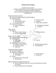
AIR INJECTION SYSTEM As shown in Fig. 15, the complete air injection system consisted of the following units:
Fig. 15. Typical air injection fuel system.
1.
An air compressor for providing an adequate supply of air at a pressure several hundred pounds higher than the engine compression pressure
2.
High pressure air bottles of sufficient capacity to provide a steady flow of high pressure air for injection as well as for engine starting.
3.
Atomizers in each engine cylinder for injecting the metered fuel by blasts of high pressure air into the combustion chamber in an adequately atomized and disbursed state.
4.
Cam mechanism for timing and lifting the atomizer valve to control the injection process.
5.
A fuel pump to meter and deliver to each atomizer the proper quantity of fuel in accordance with engine requirements of speed and load
History of Fuel Injection
AIR COMPRESSORS The air required for starting the engine and for fuel injection was generally supplied by a three-stage air compressor with stepped pistons actuated by a single crank and connecting rod. It was driven from one end of the engine crankshaft and consumed 7 to 13 percent of the indicated engine horsepower. This high power requirement was of the objectionable features of air injection.
Pressures Final pressures for each stage of a three-stage compressor ranged as follows: 40 to 90 psi for the first stage, 200 to 370 psi for the second stage, and 600 to 1150 psi for the third stage. The compressed air after each stage passed through intercoolers to reduce the air temperature to a safe value below the ignition temperature of the fuel and lubricating oil. Lowering the air temperature also served the additional purpose of (1) reducing the volume of air, and thereby the work necessary to compress it, and (2) inducing condensation of moisture in the air. At reduced speeds the spray valve was open for a longer period in absolute time so that the injection air pressure was reduced as low as 600 psi for idle. This prevented combustion knock resulting from too rapid injection of fuel, and it reduced the chilling effect on combustion of expansion of an excess of injection air. For starting at least 700 psi injection air pressure was desirable. The optimum air pressure was that which gave the lowest exhaust temperature.
Compr es s ion P roc es s For a three-stage compressor the compression process is shown in Fig. 16. If the air were compressed in a single stage, or in three stages without intercooling, the pressure volume relationship would follow the exponential compression line from 1 to A. The final temperature would to above 1500 deg. F, and the work required to compress the air would be represented by the area 1ABC. If the air were compressed isothermally, so that the heat of compression was removed continuously during compression, the work would be represented by the Fig. 16. Compression process of 3-stage compressor. area 1DBC. By compressing the air in stages and cooling it at the end of each stage, the work of compression lies between that required by exponential and isothermal compression. In the first stage the air is compressed from 1 to 1’, and after cooling its volume is reduced to 2. The second stage compression is along the exponential line 2-2’, and it is cooled along line 2’-3, etc. The shaded area represents the saving in work with staging and intercooling as compared with single-stage exponential compression. Representative conditions for a three-stage air compressor with intercooling were as follows: Compressor Stage Low pressure Intermediate High pressure Outlet
Final Pressure Psi 25-40 150-250 800-1000 800-1000
Air Temp.Suction 75 110 120
Deg. F Discharge 375 305 320 140
A ir R eq u ir em e nts Displacement of the air compressor, as measured by volume of the low pressure cylinder, was about 5 to 8 percent of the engine cylinder volume for stationery engines, and 50 to 100 percent greater than that for marine engines. Control of the compressor output was by throttling the suction or spilling the discharge from the low pressure stage. The volume of air required for efficient injection of the fuel was a function of the engine displacement and it was determined from the “mixing ratio”. This has been defined as the ratio of air volume at 882 psi (60 atmos) and 68 deg. F to the volume of fuel flowing through an atomizer during a single injection. It was determined, as shown in Fig. 17, that the mixing ratio depends only on the engine speed. It is apparent from the chart that as the engine speed increases, the time for fuel injection and Fig. 17. Mixing ratio vs. engine speed. combustion decreases so that the quantity of injection air required increases too. On a weight basis the quantity of air required per pound of fuel for mixture ratios of 15:1 and 25:1 is 1.27 pounds and 2.12 pounds, respectively.
2
History of Fuel Injection
C o mpr es s o r P ow e r The work of compressing air in a three stage compressor with perfect intercooling between stages can be obtained by the following formula: W = MRT1 3n / n-1 [1-(P2 / P1) n-1 / n] ft-lb (1) Where: • M = mols of air, 1 mol being its molecular weight of 28.8 pounds • R = universal gas constant, 1544 ft-lb per mol per degree F. • T1 = ambient air temperature, absolute temperature, degrees F. • n = exponent of compression • P2 = final air pressure, psi • P1 = atmospheric air pressure, psi Example. – Determine the percentage of power consumed by an air compressor using 2 lb. of injection air per lb. of fuel. Injection air pressure 1000 psi. Air temperature 70 deg. F. 80 percent efficiency. n = 1.28. The diesel engine has a specific fuel consumption of 0.41 lb. per bhp per hour. W= 2 x 1544 / 28.8 x 530 x 3 x 1.28 / 1.28 – 1 [1- (1000 / 14.7)0.073] = 262,000 ft-lb. Input to air compressor = 262,000 / 0.80 x 0.41 = 134,000 ft-lb per bhp output Power required to compress injection air = 134,000 / 33,000 x 60 x 100 = 6.8 per cent of engine output.
AIR BOTTLES AND PIPING Two air bottles were usually used for each engine: one for dampening the pressure fluctuations produced by the intermittent air flow from the compressor and the other one for storage of air for starting and standby. The bottles were made of seamless drawn steel tubing of about 6 to 8 inches inside diameter with a wall thickness of 1 inch. The capacity of the bottles was determined by experience. It ranged from 7 to 14 times the piston displacement, the smaller ratio applying engine cylinders larger than 22 inch diameter. The piping for the high pressure air consisted of seamless drawn steel tubing of extra heavy gauge. The main piping bore was about 4 percent of the engine cylinder bore, and the branch pipe bores were two percent of the cylinder bore.
ATOMIZERS Various types and modifications of atomizers were used. In all of them the metered fuel was delivered to the atomizer between injections, and injection occurred when its cam actuated air valve was lifted. The injection air then flowed through and out of the atomizer carrying the fuel with it and distributing it as a finely atomized spray throughout the combustion chamber. Specific fuel consumption was better with the closed atomizer (0.4l – 0.45 lb/bhp/hr) than with the open type (0.45 – 0.53 lb/bhp/hr).
Open Type Because of its simplicity this type of atomizer was used in many early horizontal engines. As shown in Fig. 18a there was a cavity or passage between the air valve and the atomizer into which the metered fuel was pumped during the engine intake stroke. This permitted the metered fuel to be delivered at low pressures, but since the cavity was always open to the combustion chamber, rapid carbonization of the fuel in it was often a problem. Turbulent flow of the injection air was usually adequate to produce an atomized spray, but sometimes perforated discs were added for an improvement.
Clos ed Type In this atomizer the cam operated valve seat was between the fuel cavity and atomizer tip to minimize carbonization. This necessitated a high pressure fuel pump since the metered fuel had to be pumped into the atomizer cavity against the air injection pressure. Three different constructions used for mixing the fuel and air to improve atomization were (1) Perforated discs, (2) Aspirating valve, and (3) Sleeve atomizer.
3
History of Fuel Injection
In the perforated disc atomizer, as shown in Fig. 2 of chapter 1, the fuel cavity surrounding the valve contained a stack of perforated discs. Each disc had as many as 36 holes of about .080 inch diameter. The number of discs varied from 5 to 8, and they were spaced about 1/8 inch apart. The discs were arranged to stagger the holes in adjacent discs for maximum turbulence of the air to promote mixing. Low viscosity oils required more discs than high viscosity oils. When the valve was lifted off its seat, the fuel deposited on the discs was entrained in the turbulent air created by the flow through the staggered holes, and it issued from orifice as well atomized spray. Fig 18b shows a perforated disc atomizer with a poppet valve which reportedly gave excellent performance. In the aspirating valve atomizer shown in Fig. 3 of chapter 1, the metered fuel was pumped into an annular space separated from but communicating with the clearance around the valve. When the valve was lifted, the outflowing injection air produced an aspirating effect on the fuel so that it was carried along and discharged as a fine spray. The sleeve atomizer shown in Fig. 18c was similar to the aspirating valve atomizer. Metered fuel was pumped into the annulus (a) around the sleeve, and when the valve was lifted the injection air flowed into the combustion chamber by first passing through holes (b) and then trough the reduced annular area around the valve stem communicating with the fuel storage annulus. Because of the reduced static pressure at this reduced area, the fuel was aspirated into the air stream and discharged as a fine spray.
Valve and Or ific e Siz e General practice was to make the valve diameter about twice the diameter of the axial hole below the valve seat, and the outside diameter of the perforated discs was about 2.25 times the valve diameter. The length of the axial hole was 1.25 times its diameter. The optimum orifice area was 90 to 100 percent of the flow past the valve seat at maximum lift. Many atomizers had a single orifice, or flame plate hole, through which the spray issued. When multiple orifices were used their total area was equivalent to that of the single orifice.
INJECTION CAM The atomizer valve timing and lift had considerable influence on combustion by controlling the beginning and rate of injection. Fig. 19, shows an “ideal” cam lift curve for an atomizer valve with a gradual ascending portion for combustion control. Since injection was almost completed at maximum valve lift, the descending portion was made as fast as possible, within stress and inertia limitations, to effect rapid seating for reducing the amount of injection air. In designing a cam it was necessary to know the dimensions of the atomizer passages, especially the valve lift required for sufficient flow area past the valve seat to discharge the fuel and air in the time required for efficient combustion. The following example presents some of the factors that were considered in the design of the atomizer and the valve actuating cam. Crank angle 15 deg. BTC 10 deg. BTC 5 deg. BTC 0 deg. TC 5 deg. ATC 10 deg. ATC 15 deg. ATC 20 deg. ATC 25 deg. ATC 30 deg. ATC 35 deg. ATC 40 deg. ATC
%Max.Lift 0 2 8 21 42 68 92 100 88 58 26 0
e=Max. valve lift/Mean valve lift=0.098in./0.046in.=2.12
Fig. 19. Valve lift of an ideal atomizer cam.
Example. Design a fuel cam for a one cylinder, 29.13 inch bore by 47.24 inch stroke, 4 cycle diesel engine developing 460 i.h.p. at 125 rpm using a perforated disc atomizer. The specific fuel consumption is assumed to be 0.32 lb/i.h.p./hr with oil of 0.86 specific gravity. The weight of fuel injected per cycle is: 460 x 0.32 x 2 / 60 x 125 = 0.0393 lb. Since one cubic inch of water weighs 0.0361 lb, the volume of fuel per cycle is: 0.0393 / 0.0361 x 0.86 = 1.26 cu.in.
4
History of Fuel Injection
From the curve in Fig. 3 the mixing ratio is found to be 15. Then the volume of injection air per cycle at 60 atmospheres and 68 degrees F is: 1.26 x 15 = 18.9 cu.in. This volume of air must pass through the nozzle and expand down to the engine compression pressure of 30 to 35 atmospheres. Although the compression pressure varies somewhat during injection, it is assumed that it remains constant at 35 atmospheres. The air temperature is also assumed to remain constant at 68 deg F. since the temperature drop on expansion is offset by the heat taken in from the walls. Thus the volume of outflowing air: 18.9x(60+1)/(35+1)=32 cu.in. The total volume of fuel and air is: 1.26+32=33.3 cu.in. This volume must flow past the valve seat with the flow area increasing from zero when the valve is closed to a maximum at full lift. The flow area past the 60 degree seat is a function of the axial hole or “channel” diameter below the seat as shown in Fig. 20. From the formula for air in the subcritical region, where P0/p1>0.53, the air/fuel velocity is: W0 = CV √{2g x K / (K-1) x P1 x V1 [ 1 – (P0 / P1)K-1/K ] } ft/sec (2) Where: • CV = the velocity coefficient of flow, taken as 0.8 • K = the coefficient of expansion for air, assumed 1.4 • P0 = the initial air injection pressure of 60 atmos. = 61 atmos. abs. • P1 = the final (combustion chamber) pressure of 35 atmos. = 36 atmos. abs. • V1 = the total volume of air and fuel per injection, 33.3 cu.in. • T1 = the initial temperature, 68 + 460 = 528 deg. F. abs. By substituting RT1 for P1V1, where R = 53.3 ft-lb per feg F., the equation (2) becomes: W0 = 109.4 CV √{T1 [1-(P0/P1)0.286] } ft/sec (3) Then by substitution, W0 = 761 ft/sec. For a valve lift opening period of 55 crank degrees, as shown in Fig. 19, the duration of injection is: 55 x 60 / 125 x 360 = 0.733 seconds Then to discharge the volume of air and oil of 33.3 cu.in. in 0.733 seconds, the mean flow area past the valve seat is: 33.3 / 12 x 761 x 0.733 = 0.050 sq.in. The valve lift and channel diameter can now be determined with the aid of Figs. 19 and 20. Selecting a channel diameter of 16 mm, the mean valve lift for a flow area of 0.50 sq.in. is 0.068 inch. From the relationship given in Fig. 19, this corresponds to a maximum valve lift of 0.068 x 2.12 = 0.144 inch, which is acceptable. The required valve lift curve can be determined by multiplying the lift percentages at various crank angle positions of the ideal cam in Fig. 19 by 0.144. This gives a valve lift curve from which the cam shape can be developed. In order to allow for tappet roller play, the cam must have a ramp with a dwell of 5 to 10 degrees to take up the clearance just before the valve lifts. In the development the base circle is parallel to the zero base line for a distance equal to the roller play. The clearance for this application was made .020 inch, and the desired lift curve is shown in Fig.21.
FUEL PUMPS Plunger type pumps with one element for each engine cylinder were used. Leakage by the plungers in early pumps was prevented by packed glands. Later pumps employed lapped plunger and barrel assemblies to minimize leakage. The pumps were designed to operate at pressures sufficient only to overcome the maximum air injection pressure of 1100 psi. In the representative pump shown in Fig. 15, each pumping element contained a spring loaded suction valve to admit the fuel, and the fuel quantity was controlled by holding the suction valve off its seat during part of the plunger delivery stroke. An eccentric was used to actuate the plunger. These pumps were cumbersome and expensive. Any of the present day commercial jerk pumps would be less expensive, but more accurate in the distribution of fuel to the various engine cylinders.
ENERGY OF ATOMIZATION Excellent atomization was obtainable with lower pressures and less expenditure of energy with air injection than with pressure of solid injection. This is readily apparent from calculations of the energy released in the two processes of injection. For an air injection at 850 psi and 60 deg F., average combustion chamber pressure of 650 psi, and injection air rate of 2 lb per 1 lb of fuel, the energy released by the air in isothermal expansion is: Ea = MRT loge P1/P2 = 2 x 53.3 x 520 loge 850/650 = 15,000 lb/lb.fuel The energy released from 1 lb. of fuel of 53 lb. per cu.ft of fuel is: pressure energy released = volume x pressure drop, so that: Ef = 1/53 x (850- 650) 144 = 540 ft/lb. The total energy with air injection is then 15,000 + 540 = 15,540 ft. lb/lb. With pressure injection at 6200 psi into air at 500 psi the energy released is, Ef = 1/53 x (6200-500) 144 = 15,500 ft-lb/lb fuel. Thus with air injection, using twice as much air by weight as fuel, a pressure drop of only 200 psi releases as much energy for atomization as a 5700 psi drop with pressure injection.
5