High Power Laser Shutter User Manual
2016 version L0.04
Contents 1.
Introduction ___________________ 3
1.1
Short description __________________ 3
1.2
General safety requirements _________ 3
1.3
Symbols _________________________ 3
1.4
Regulation _______________________ 3
1.5
Operating and storage conditions _____ 4
2.
Package contents _______________ 4
3.
Operation principle ______________ 5
4.
Specifications __________________ 5
4.1
5.
Shutting characteristics _____________ 6
Operation manual _______________ 7
5.1
Alignment ________________________ 7
5.2
Detailed description of switchers _____ 8
5.3
Control via RS232 port ______________ 9
2
While assembling or operating the shutter, do not stare
1. Introduction
at the direct or scattered laser light even with safety goggles. All parts of the body must be kept away from the
This user manual is designed to help to install and
laser radiation. While adjusting laser beam through the
operate High Power Laser Shutter. Before installing and
shutter, laser power must be kept as low as possible.
operating the product please read installation and
Hazardous laser radiation can increase while optical
operation instructions carefully. Safety instructions must
components or instruments are used in combination
be read carefully. If there are any questions about
with the shutter. Appropriate eye protection must be
contents
worn at all times. Electrical safety requirements must be
of
this
manual
please
contact
[email protected]. Altechna reserves the right to
complied while assembling and operating the shutter.
update contents of this manual without any notification.
1.3 Symbols 1.1 Short description High Power Laser Shutter is designed for fast single interruption or multiple exposure of high power laser beam. It can be utilized as safely device for fast laser beam shutting as well as a device for modulating laser beam exposure time or pulse trains. It can be controlled
Warning! Sections marked with this symbol explain dangerous situations that can result as personal injury or death. Always read the associated information carefully, before performing indicated procedure.
either manually, or via computer by sending TTL signal from external signal generator via BNC connection or
Attention!
commands via serial port. Paragraphs preceded by this symbol explain hazards that could damage the instrument and connected
1.2 General safety requirements
equipment or may cause loss of data.
High Power Laser Shutter is designed to operate in
Note
conjunction with laser systems. All applicable rules and regulations for safe operation of lasers must be known
This manual also contains “NOTES” and “HINTS” written in this form.
and applied while installing and operating the shutter. The user is solely responsible for laser safety while using
1.4 Regulation
High Power Laser Shutter as a standalone device or integrated into system. The user must consider
Attention!
protective measures. The following statement applies to the products covered in this manual, unless otherwise specified herein. The
3
statement for other products will appear in the
Cellular phones or other radio transmitters are not
accompanying documentation.
recommended to be used within the range of three meters of this unit since the electromagnetic field
These limits are designed to provide reasonable
intensity may then exceed the maximum allowed
protection against harmful interference in a residential
disturbance values according to IEC 61326-1.
installation. This equipment generates, uses, and can create radio frequency energy and, if not installed and
1.5 Operating and storage conditions
used in accordance with the instructions, may cause harmful interference with radio communications.
For proper High Power Laser Shutter functioning please
However, there is no guarantee that interference will not
use the assigned controller (found in the same package).
occur in a particular installation. If this equipment
Using unassigned controllers might be harmful to the
causes harmful interference to radio or television
device.
reception, which can be determined by turning the equipment off and on, the user is encouraged to try to correct the interference by one or more of the following measures:
Environmental conditions that must be hold while storing, servicing and operating are: • Storage temperature should be between -25 °C and
•
Reorient or relocate the receiving antenna.
•
Increase the separation equipment and receiver.
between
+60 °C. the
•
Connect the equipment into an outlet on a circuit different from that to which the receiver is connected.
•
Consult the dealer or an experienced radio/TV
• Operating temperature is 25 °C ± 10 °C. • High Power Laser Shutter must be protected from humidity, dust and corrosive vapors to avoid damaging optical components and electronics. • Avoid strong static electricity and electromagnetic fields.
technician for help.
2. Package contents Altechna is not responsible for any radio or television interference caused by modifications of this equipment
High Power Laser Shutter package includes:
or the substitution or attachment of connecting cables and equipment other than those specified by Altechna.
• Laser shutter head
The correction of interference caused by unauthorized
• Controller
modification, substitution or attachment will be treated
• RS232 cable (to connect the shutter to the controller)
as responsibility of the user.
• Ø10 mm optics adapters • Ø2 mm beam alignment adapters
Attention!
• Power Cable • User manual and serial command list in USB drive
4
3. Operation principle Operation of the shutter is based on the fast galvanomagnetic scanner. Scanner is incorporated in
4. Specifications Characteristic
Rating
Beam diameter
10 mm
Pulse energy, µJ
≤0.3µJ
Laser beam polarization
any
Max laser power, W
≤20
Switching frequency range, Hz
0-200
nondispersive optical system to achieve speed of blanking better than parts of milliseconds. This design ensures both- high speed and high damage threshold of the shutter.
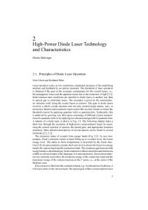
Construction of the shutter is based only on reflecting non-focusing optics and is presented in Fig.1.
Switching time (closed-opend), ≥0.2 / 1 ms
Figure 1. Beam diagram of collinear shutter. M1-rotating galvo mirror, M2-M4-adjustable 100% metal mirror.
Typical switching time (opened-opened), ms
≥0.5 /2
Control via RS232 port, TTL signal
Yes
Control from external (0-5V) generator
Yes
Control from internal (0-5V) generator
Yes
Manual control
Yes
Manual switching
Yes
Shutter position indication
Yes
Sinchro output
Yes
Shutter dimensions, mm
185 x 40 x 60
Controller dimensions, mm
252 x 145 x 74
Electrical power consumption, W
≤30
System includes: galvo driver and mount, power supply, galvo mirror, standard cable
(Master-Slave) for connecting controller with PC, cable for connecting galvo driver. As an option dpss green or red diode laser should be applied for system alignment (not included).
5
4.1 Shutting characteristics Main parameters of the shutter are opening/closing time and residual scattered light. Typical shutter operation results in the range of 10-250Hz are presented in Fig 3a and Fig 3b. The noise is attributed to the fact that the photodiode used for testing did not have either optical or electronic filters for suppressing background noise. The testing was performed using a 700 nm red laser.
Figure 2. Main temporal parameters of the shutter.
Figure 3b. Typical CW Ø1.5mm laser beam modulation oscilograms at 50Hz, 100Hz, 200Hz and 250Hz rates.
Figure 3a. Typical CW Ø1.5mm laser beam modulation oscilograms at 1Hz and 10Hz rates.
6
5. Operation manual
beam has disappeared; i.e. is not visible at the output. Now the shutter is ready for operation.
5.1 Alignment To align the shutter with the laser beam, the following actions should be performed:
1.
Align guiding beam with the high power operating beam (if operating before shutter beam is invisible) and turn off the high power beam, or set it to harmless power level if it will be used to guide beam.
2.
The beam must enter the shutter through the center of the entrance hole (use housingengraved arrow for reference). Make sure the beam that is entering the shutter is at right angle with respect to the housing. It is Figure 4. Shutter controller front and back panels.
recommend to place a mirror with