Handling Instructions DBD-Series 0-180 degree Rebar Benders Benner-Nawman, Inc. 3450 Sabin Brown Road Wickenburg, AZ 85390 (800) 992-3833 (928) 684-2813 FAX: (928) 684-7041
[email protected] www.bnrebartools.com
November 2006
1
When using electric tools, basic safety precautions should always be followed to reduce the risk of electric shock and personal injury, including the followings items: READ ALL INSTRUCTIONS AND SAVE THEM FOR FURTURE REFERENCE. 1. Keep hands away. From all moving parts and rollers while operating. 2. Dress properly. Loose clothing or jewelry can get caught in moving parts. Wear sturdy boots with non-skid soles. Steel toed boots and safety glasses are recommended. 3. Keep children and bystanders away. Distractions can cause you to lose control. 4. Do not overreach. Keep proper footing and balance at all times. This enables better control of the power tool in unexpected situations. 5. Stay alert. Watch what you are doing and use common sense when operating a power tool. Do not use a power tool while you are tired or under the influence of drugs or alcohol. A moment of inattention while operating power tools may result in serious personal injury. 6. Do not exceed the maximum number of bars that can be bent at one time. Please refer to specifications on page 3 -4. 7. When positioning the bar between rollers, make sure to lay it flat on the machine surface. Failure to do so may cause the rebar to fly out. 8. Do not expose tool to rain or use in damp locations.. Do not use tool in presence of flammable liquids or gases. Keep work area well lit. If the tool is used outdoors, keep it covered when not in use and protect it from rain or water. 9. Do not try to bend materials harder than “Grade 60 or 600N/mm2” as they will either crack and fly out or cause machine failure. 10. Disconnect tool from receptacle when not in use. Disconnect when servicing or changing rollers to prevent accidents. 11. Keep tool clean at all times for best and safest performance. Follow instructions for lubricating and changing parts. Keep hands dry and free of oil or grease. Inspect switches, tool cords periodically and have them repaired or replaced by an authorized service center if damaged. Check moving parts for alignment and binding as well as for breakage and improper mounting. Damaged parts should be repaired or replaced by an authorized service facility unless otherwise indicated in this instruction book.
NOTE: READ ALL INSTRUCTIONS AND SAVE THEM FOR FUTURE REFERENCE
Benner-Nawman, Inc.
2
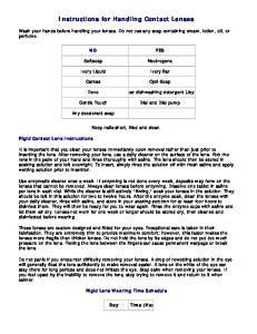
DBD-16X / DBD-20X 1. Moving bending roller 2. Center roller 3. Adjustable stopper 4. Main switch 5. Pilot lamp 6. Operation button On/Off 7. Angle setter (dial type) 8. Angle stopper (Left & Right) 9. Emergency stop button 10. Plug-in for foot switch 11. Roller set 12. Foot Operated Switch
2
1
3
5 6
4 9
7
10
8
12 11
SPECIFICATIONS Model Max. Bending Capacity Bending Angle Bending Speed Electric Power Supply Dimensions L x W x H (mm) Weight (Kg)
DBD-16X 5/8” (#5) (16 mm) Grade 60 Rebar 0-180° 5 seconds for 180° bend 115 Volts, 50/60Hz, 10 amps, 1050 watts 16.6” x 12.5” x 16.2” (425) x (320) x (415) 90 lbs. (40.8)
1
2
DBD-20X 3/4" (# 6) (19 mm) Grade 60 Rebar 0-180° 7 seconds for 180° bend 115 Volts, 50/60 Hz, 15 amps, 1725 watts 16.4” x 18” x 16.2” (420) x (462) x (415) 134.5 lbs (61)
DBD-25X / DBD-32X (foot operated switch included #12) 3
4 5 6
8 9
10
Model Max. Bending Capacity Bending Angle Bending Speed Electric Power Supply Dimensions (L x W x H) Weight (Kg)
7
1. Moving bending roller 2. Center roller 3. Adjustable stopper 4. Main switch 5. Pilot lamp 6. Operation button On/Off 7. Angle setter 8. Angle stopper 9. Emergency stop button 10. Plug in for foot switch
DBD-25X 7/8” (#7) (22 mm) Grade 60 Rebar 0-180 Degrees 6 Seconds for 180 degree bend 115 Volts, 50/60Hz, 12 amps, 1150 watts 19” x 21.5” x 17.2” (490) x (550) x (440) 190 lbs (86)
3
DBD-32X 1 1/8” (# 9) (29 mm) Grade 60 Rebar 0 – 180 Degrees 8 Seconds for 180 degree bend 115 Volts, 50/60 Hz, 12 amps, 1380 watts 23” x 24.2” x 18.7” (590) x (620) x (480) 397 lbs (180)
DBD-16X Rebar Bender Roller Selection Chart Rebar Diameter Size # 3 (3/8”) (10mm) # 4 (1/2”) (13 mm) # 5 (5/8”) (16 mm)
Center Roller # 5 (1.88” diameter) # 3 (2.50” diameter) # 1 (3.00” diameter)
Moving Roller # 6 (4.11” diameter) # 4 (3.19” diameter) # 2 (2.44” diameter)
# of Grade 60 Rebar Bent 3 pieces at one time 2 pieces at one time 1 piece at one time
DBD-20X Rebar Bender Roller Selection Chart Rebar Diameter Size # 6 (3/4”) (19mm) # 5 (5/8”) (16 mm) # 4 (1/2”) (13 mm) # 3 (3/8”) (10 mm)
Center Roller # 4 (3.71” diameter) # 4 (3.71” diameter) # 3 (2.93” diameter) # 1 (2.22” diameter)
Moving Roller # 2 (2.65” diameter) # 3 (2.93” diameter) # 5 (3.90” diameter) # 6 (4.80” diameter)
# of Grade 60 Rebar Bent 1 piece at one time 2 pieces at one time 3 pieces at one time 4 pieces at one time
DBD-25X Rebar Bender Roller Selection Chart Recommended Bending Roller Selection Chart for DBD-25X Bender on Standard Hook Details Combination of Center Roller and Moving Roller according to the bar size: Bar Diameter Size Center Center Roller CRSI Recommended Inside Bend Diameter Max. Grade 60 Roller # Outside Diameter 7 /8” (22mm) #7 No. 5 4.75” (120mm) 5.25” (134mm) ¾” (19mm) #6 No. 5 4.75” (120mm) 4.50” (115mm) 5 /8” (16mm) #5 No. 4 3.75” (96mm) 3.75” (96mm) ½” (13mm) #4 No. 3 3.12” (79mm) 3.00” (76mm) 3 /8” (10mm) #3 No. 1 1.95” (50mm) 2.25” (57mm) ** Use a second No. 4 Roller on moving roller to produce a complete 180° Bend.
Moving Roller No. 1 No. 1 No. 3** No. 5 No. 6
No. of bars that can be bent at one time 1 -Piece 2 -Pieces 2 -Pieces 3 -Pieces 4 -Pieces
Recommended Bending Roller Selection Chart for DBD-25X Bender on Stirrup Hooks Combination of Center Roller and Moving Roller according to the bar size: Bar Diameter Size Center Center Roller Max. Grade 60 Roller # Outside Diameter 5 /8” (16mm) #5 No. 1 1.95” (50mm) ½” (13mm) #4 No. 1 1.95” (50mm) 3 /8” (10mm) #3 1.63” (42mm) ** ** Use roller shaft only with no roller.
CRSI Recommended Inside Bend Diameter 2.50” (51mm) 2.00” (51mm) 1.50” (38mm)
Moving Roller No. 6 No. 6 No. 6
No. of bars that can be bent at one time 2 -Pieces 3 -Pieces 4 -Pieces
Bending Roller Sizes for DBD-25X Bender Only Part Number -Roller Number #1BR5140 -No. 1 #1BR5142 -No. 2 #1BR 5143 -No. 3 #1BR51441 -No. 4 #1BR51451 -No. 5 #1BR5146 -No. 6
Outside Diameter 1.95” (50mm) 2.73” (70mm) 3.12” (79mm) 3.75” (96mm) 4.75” (120mm) 6.13” (156mm) 4
Note: CRSI (Concrete Reinforcing Steel Institute) recommends the finished inside bend diameter or center roller outside dimension for standard hooks be 6 times the bar diameter from #3 to #8, and 8 times the diameter for #9, #10 and #11 rebar. For #3, #4 and #5 stirrup hooks it’s only 4 times the bar diameter, #6, #7 and #8 are again 6 times.
DBD-32X Rebar Bender Roller Selection Chart TABLE A Roller Selection Chart for DBD-32X Only Combination of Center Roller and Moving Roller according to the bar size: No. of bars that Bar Diameter Center Moving can be bent at one Size Grade 60 Roller Roller time 1 1- /8” (29mm) #9 No. 5 No. 2 1 Piece 1” (25mm) #8 No. 5 No. 3 1 Piece 7 /8” (22mm) #7 No. 5 No. 3 1 Piece ¾” (19mm) #6 No. 4 No. 3** 2 Pieces 5 /8” (16mm) #5 No. 3 No. 5 2 Pieces ½” (13mm) #4 No. 2 No. 6 3 Pieces 3 /8” (10mm) #3 No. 1 No. 7 4 Pieces ** Use a second No 4 Roller on moving roller to produce 180° Bends
TABLE B Roller Sizes Part Number -Roller # Outside Diameter #1BR7090 -No. 1 1.95” (50mm) #1BR7091 -No. 2 2.73” (70mm) #1BR70931 -No. 3 3.50” (89mm) #1BR70941 -No. 4 4.31” (110mm) #1BR70951 -No. 5 5.06” (129mm) #1BR70961 -No. 6 6.13” (156mm) #1BR7097 -No. 7 7.44” (189mm)
WARNING: ALWAYS UNPLUG TOOL BEFORE ATTACHING OR REMOVING ROLLERS OR ACCESSORIES. 1. Select and set the correct rollers for the bars to be bent. See the table on page 3 - 4. 2. Plug the electrical power cord into an appropriate outlet. 3. Lay the bar on the machine surface between the center roller and bending roller. Adjust the stopper so that the bar is parallel to the front edge of the machine. 4. Turn the main switch on and check that the pilot lamp has lit up. 5. Set the angle and make a test bend. If the bent angle is not exact, adjust the angle setter slightly to the right or left. Lock in the angle stoppers to duplicate the same angle each time. 6. Push the operation button or foot switch. The moving bending roller will automatically return to the start position once the bend has been completed.
6 7
7. If it is necessary to stop the machine in an emergency, push the emergency stop button or release your foot from the foot operated switch. The bending roller will return to the start position automatically.
5
Benner-Nawman, Inc. (2) BENDING ANGLES CAN BE PRESET 1. Set the angle setter to 135° then tighten the right angle stopper to lock the 135° position. 2. Set the angle setter to 90° then tighten the left angle stopper to lock the 90° position.
3. Set the angle setter to 135°. Push the operation button to make your first bend.
EXAMPLE: 135°
4. Slide the rebar to the desired length and set the angle setter to 90°. Push the operation button to complete your second bend.
90° For stirrups, cut your rebar to the desired length before bending. Then make both bends for your turndowns. Finally make your (3) 90° bends to connect your ends together. See chart (left)
1 2
3
WARNING: Never touch any moving parts or rollers while the rebar bender is being operated.
4
6
INSPECTION AND MAINTENANCE WARNING: ALWAYS UNPLUG TOOL BEFORE PERFORMING MAINTENANCE. DO NOT USE PARTS OR ACCESSORIES THAT ARE NOT GENUINE
DIAMOND brand from Benner-Nawman, Inc. 1. At least once a month remove the bottom plate and grease all the visible gears and pinions. At the same time, check the carbon brushes for wear or damage. Replace with new brushes if they are worn out.
(wear limit→replace carbon brushes) 6mm (¼”)
17 mm (21/32”) total length
2. Check that there are no loose nuts and bolts before starting the operation. 3. After operation is completed, be sure to remove metal dust, dirt, oil, etc… adhering to the machine surface. 4. In order to empty the metal dust from the bender, (remove side cover DBD-25X and DBD32X models) then tilt the machine to one side allowing the debris to fall out of the catch pan. Be sure to blow out any remaining dirt and dust with compressed air prior to using the tool again (wear safety goggles to block blowing debris).
BENDER OPTIONS Our benders have a multitude of options available, pictured for left to right: DBC-20X or DBC25X side by side combination rebar cutter & bender, stand only for benders except for DBD16X, hand truck cart for DBD-16X bender in combination with a rebar bender & cutter, and DBC-Series stand type combination rebar bender and cutter units. Trailer units not pictured.
7