GRUNDFOS INSTRUCTIONS
Conlift Installation and operating instructions
Declaration of Conformity
Konformitätserklärung
We Grundfos declare under our sole responsibility that the products Conlift, to which this declaration relates, are in conformity with these Council Directives on the approximation of the laws of the EC Member States:
Wir Grundfos erklären in alleiniger Verantwortung, dass die Produkte Conlift, auf die sich diese Erklärung bezieht, mit den folgenden Richtlinien des Rates zur Angleichung der Rechtsvorschriften der EUMitgliedsstaaten übereinstimmen:
–
Machinery Directive (2006/42/EC). Standard used: EN 809: 2000.
–
Maschinenrichtlinie (2006/42/EG). Norm, die verwendet wurde: EN 809: 2000.
–
Low Voltage Directive (2006/95/EC). Standards used: EN 60335-1: 2007 and EN 60335-2-41: 2003*).
–
–
EMC Directive (2004/108/EC). Standards used: EN 61000-6-2 and EN 61000-6-3.
Niederspannungsrichtlinie (2006/95/EG) Verwendete Normen: EN 60335-1: 2007 und EN 60335-2-41: 2003*).
–
EMV-Richtlinie (2004/108/EG). Verwendete Normen: EN 61000-6-2 und EN 61000-6-3.
*) The lifting station must be protected against splashing water (in compliance with IP X4).
*) Die Hebeanlage muss so aufgestellt werden, dass sie gegen Spritzwasser geschützt ist (entsprechend IP X4).
Déclaration de Conformité
Dichiarazione di Conformità
Nous Grundfos déclarons sous notre seule responsabilité que les produits Conlift, auxquels se réfère cette déclaration sont conformes aux Directives du Conseil concernant le rapprochement des législations des Etats membres CE relatives à/au(x):
Grundfos dichiara sotto la sua esclusiva responsabilità che i prodotti Conlift, ai quali si riferisce questa dichiarazione, sono conformi alle seguenti direttive del Consiglio riguardanti il riavvicinamento delle legislazioni degli Stati membri CE:
–
Directive Machines (2006/42/CE). Norme utilisée : EN 809 : 2000.
–
Direttiva Macchine (2006/42/CE). Norma applicata: EN 809: 2000.
–
Directive de basse tension (2006/95/EC) Normes utlisées: EN 60335-1: 2007 et EN 60335-2-41: 2003*).
–
Direttiva Bassa Tensione (2006/95/CE). Norme applicate: EN 60335-1: 2007 e EN 60335-2-41: 2003*).
–
Compatibilité électromagnétique (2004/108/EC) Normes utlisées: EN 61000-6-2 et EN 61000-6-3
–
Direttiva EMC (2004/108/CE). Norme applicate: EN 61000-6-2 e EN 61000-6-3
*) Le récupérateur doit être installé de manière à être protégé des projections d’eau (selon IP X4).
*) La stazione di sollevamento deve essere protetta dagli spruzzi d'acqua (secondo IP X4).
Overeenkomstigheidsverklaring Wij Grundfos verklaren, geheel onder eigen verantwoordelijkheid, dat de producten Conlift, waarop deze verklaring betrekking heeft, in overeenstemming zijn met de Richtlijnen van de Raad inzake onderlinge aanpassing van de wetgevingen van de Lidstaten. –
Konedirektiivi (2006/42/EY). Sovellettu standardi: EN 809: 2000.
–
Laagspannings Richtlijn (2006/95/EC) Gebruikte normen: EN 60335-1: 2007 en EN 60335-2-41: 2003*).
–
EMC Richtlijn (2004/108/EC). Gebruikte normen: EN 61000-6-2 en EN 61000-6-3
*) Het hevelstation moet beschermd worden tegen opspattend water (in overeenstemming met IP X4).
Deklaracja zgodności
Overensstemmelseserklæring Vi Grundfos erklærer under ansvar at produkterne Conlift, som denne erklæring omhandler, er i overensstemmelse med disse af Rådets direktiver om indbyrdes tilnærmelse til EF medlemsstaternes lovgivning: –
Maskindirektivet (2006/42/EF). Anvendt standard: EN 809: 2000.
–
Lavspændingsdirektivet (2006/95/EC). Anvendte standarder: EN 60335-1: 2007 og EN 60335-2-41: 2003*).
–
EMC-direktivet (2004/108/EC). Anvendte standarder: EN 61000-6-2 og EN 61000-6-3
*) Beholderanlægget skal installeres, så det er beskyttet mod vandsprøjt (i henhold til IP X4). Bjerringbro, 15 April 2010
My Grundfos, oświadczamy z pełną odpowiedzialnością, że nasze wyroby Conlift, których deklaracja niniejsza dotyczy, są zgodne z następującymi wytycznymi Rady d/s ujednolicenia przepisów prawnych krajów WE: –
Dyrektywa Maszynowa (2006/42/WE). Zastosowana norma: EN 809: 2000.
–
Dyrektywa Niskich Napiêæ (2006/95/WE), Zastosowane normy: EN 60335-1: 2007 i EN 60335-2-41: 2003*).
–
Dyrektywa EMC (2004/108/WE), Zastosowane normy: EN 61000-6-2 en EN 61000-6-3
*) Agregat pompowy musi być zabezpieczony przed możliwością opryskiwania wodą (zgodnie z wymaganiami dla stopnia ochrony IP X4).
2
Svend Aage Kaae Technical Director Grundfos Holding A/S Poul Due Jensens Vej 7 8850 Bjerringbro, Denmark Person authorised to compile technical file and empowered to sign the EC declaration of conformity.
Conlift Installation and operating instructions
4
Montage- und Betriebsanleitung
18
Notice d'installation et d'entretien
33
Istruzioni di installazione e funzionamento
47
Installatie- en bedieningsinstructies
61
Monterings- og driftsinstruktion
75
Instrukcja montażu i eksploatacji
89
3
1. Symbols used in this document
Original installation and operating instructions.
CONTENTS
Warning If these safety instructions are not observed, it may result in personal injury!
Page 1.
Symbols used in this document
4
2.
Delivery
4
3. 3.1
General description Applications
5 5
4.
Function
5
5. 5.1 5.2 5.3 5.4
Installation Connections Lifting station Dimensions Connection of inlet and discharge hoses
6 6 6 6 8
6.
Electrical connection
10
7. 7.1
Start-up Checking the function
10 10
8. 8.1 8.2
Maintenance and service Cleaning the Conlift Contaminated lifting station or components
11 11 11
9. 9.1 9.2
Components Service kit Accessories
12 13 15
10.
Fault finding chart
16
11. Technical data 11.1 Other technical data
17 17
12.
17
Disposal
Warning Prior to installation, read these installation and operating instructions. Installation and operation must comply with local regulations and accepted codes of good practice. Warning The use of this product requires experience with and knowledge of the product. Persons with reduced physical, sensory or mental capabilities must not use this product, unless they are under supervision or have been instructed in the use of the product by a person responsible for their safety. Children must not use or play with this product.
4
Caution
Note
If these safety instructions are not observed, it may result in malfunction or damage to the equipment! Notes or instructions that make the job easier and ensure safe operation.
2. Delivery The Grundfos Conlift is delivered in a cardboard box containing: • Conlift lifting station with built-in non-return valve and supply cable with Schuko plug or a free cable end • Mounting kit in plastic bag • Installation and operating instructions. The mounting kit consists of (see pages 12 and 13): 5 metres of hose with internal/external diameter of 10/14 mm (pos. 51) • 2 angular mounting brackets to counteract buoyancy (pos. 52) • 4 wood screws (pos. 53) and 4 rawlplugs ® (pos. 54) • 1 hose clamp for fastening the discharge hose to the discharge stub (pos. 55) • 4 mounting feet to be glued on (pos. 56) • 1 strain-relief – for the use of external alarm/ potential-free contact (pos. 19) • 2 sheet metal screws for the strain-relief (pos. 20). Check that all components are OK.
3. General description
4. Function
The Grundfos Conlift is a compact lifting station with built-in non-return valve; it works automatically. The Conlift is ready for installation.
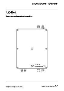
The condensate flows by natural gravitation through a hose into the lifting station, see section 5. Installation. When the liquid level in the collecting tank reaches 60 mm, the pump starts automatically via pressure switch 1. When the liquid level falls below 35 mm, the pump stops. The condensate is pumped through the discharge hose to the drain. If the liquid level rises above 80 mm, the alarm (buzzer) is activated via pressure switch 2 (alarm pressure switch), and the pump starts (second cutin).
3.1 Applications The Conlift is designed for the pumping of condensate from • boilers • air-conditioning systems • cooling and refrigeration systems • air dehumidifiers • evaporators. The Conlift is suitable for the pumping of condensate which is collected below sewer level or which cannot flow to the sewage system or drain of the building by natural gravitation. The Conlift must only operate in 1.5 out of 10 minutes (S3 - 15 %) according to DIN VDE 0530 T1.
Note
Stop Aus
Fig. 1
TM02 7495 1104
Start Ein
35
The Conlift can pump condensate with a pH value equal to or above 2.7 from boilers with a heat output of up to 200 kW. This applies to boilers fired with the following: • gas • liquid gas • low-sulphur fuel oil according to DIN 51 603-1.
Alarm Alarm
80
Warning Condensates from boilers are aggressive. They contain acid.
60
Caution
Stop, start and alarm levels
Where boilers are fired with the above fuels, but • have a heat output above 200 kW, • produce condensate with a pH value below 2.7, and where boilers • are fired with oils other than lowsulphur fuel oil, the condensate from the boiler must be neutralised before entering the sewage system/lifting station. Warning The Conlift must not be used for the transfer of inflammable liquids. Warning The Conlift must not be installed in potentially explosive environments.
In case of deviations from the application conditions stated above, local electricity regulations and standards must be observed. In case of doubt, contact a qualified electrician.
5
5. Installation Note
• • • • •
5.1 Connections See fig. 2.
The Conlift lifting station must be installed in accordance with local regulations.
The condensate must flow freely into the lifting station. The cooling slots in the motor cover must not be covered. Easy access to the lifting station must be provided to facilitate maintenance. The lifting station must be installed in a wellilluminated and -ventilated room. The lifting station must be protected against splashing water (in compliance with IP X4).
Connection for inlet hose: Inlet opening in collecting tank, internal diameter 24 mm. Connection for discharge hose: Discharge stub above the built-in non-return valve, external diameter 12 mm. Electrical connection: Supply cable with Schuko plug or a free cable end, 2 metres.
5.2 Lifting station The Conlift must be mounted horizontally. The Conlift can be mounted on the floor or on the wall. Drilling template for the holes for wall mounting can be found at the end of this booklet. Depending on the type of mounting, the mounting feet must be glued on the bottom or back of the Conlift.
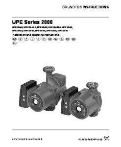
5.3 Dimensions 160.5
106
Discharge stub
99
144
199
100
12
245 220
171 5
Inlet opening
Fig. 2
6
Dimensional sketch
TM02 7496 3603
6.5
15
55
Electricity supply
5.3.1 Securing the Conlift Warning To prevent personal injury caused by electric shock, scalding hot water or acid, do not turn the Conlift upside down.
In rooms where there is no risk of flooding, the angular mounting brackets also prevent accidental • overturning of the lifting station (floor mounting) or • detachment of the lifting station from the wall (wall mounting). This prevents the acid in the collecting tank from spilling out and causing damage.
If the Conlift is installed in a room where there is a risk of flooding, the angular mounting brackets must be used. They counteract the buoyancy of the Conlift (see figures 3 and 4), and thus prevent the collecting tank from tilting and the spillage of acid. Sicherungthe gegen Auftrieb und ungewolltes Umstoßen Securing Conlift to counteract buoyancy and to(Säure) prevent accidental overturning (acid)
TM02 7499 3603
R >> 60 R 60mm mm
Fig. 3
Floor mounting, securing the Conlift to counteract buoyancy
TM02 7498 3603
Sicherung gegen Auftrieb ungewolltes Umstoßen (Säure) Securing the Conlift tound counteract buoyancy and to prevent accidental detachment from the wall (acid)
Fig. 4
Wall mounting, securing the Conlift to counteract buoyancy
The Conlift must be mounted horizontally and secured by screws as shown in figures 3 and 4. The Conlift must be mounted in a dry and frost-free room with good ventilation. The angular mounting brackets counteract buoyancy, e.g. in connection with temporary flooding.
7
5.4 Connection of inlet and discharge hoses The hose supplied as an accessory can be used as inlet and discharge hose. • Attach the hose to the wall. Distance between attachment points: Approx. 30 cm. • Make sure that the hose does not sag or is squeezed. • Avoid sharp bends. The bending radius of the hose must be at least 60 mm. • Run the inlet and discharge hoses in such a way that they do not strain the Conlift. 5.4.1 Inlet hose • When running the inlet hose from the boiler or cooling/air-conditioning system to the Conlift, make sure that the condensate flows freely into the collecting tank. • Insert the inlet hose sufficiently deep into the tank through the inlet opening, see fig. 7. It is recommended to make a sloping cut to the hose. 5.4.2 Discharge hose • Pass the discharge hose end over the discharge stub (the grommet should not be lubricated with grease), see fig. 7. Fasten the hose with the clamp supplied with the lifting station. • Take the discharge hose vertically up to the highest point from where the condensate can flow freely into the sewage system or drain of the building. • If the Conlift is positioned below sewer level, the hose must have a return loop at the highest point. The lower edge of the loop must be 10 to 20 cm above sewer level (the sewer level usually corresponds to the street level). • At the highest point, a loop must be formed. The bending radius of the hose must be at least 60 mm. Hose end to be connected to Schlauchende zum sewage system or drain Freigefälleanschluss
R > 60 mm R > 60 mm
Fig. 5
8
Arrangement of hoses
TM02 7500 3603
RR > 60 60mm mm
5.4.3 External alarm/potential-free contact Warning Before starting work on the Conlift, the electricity supply must be switched off. It must be ensured that the electricity supply cannot be accidentally switched on. Work on electrical systems and components must only be carried out by a qualified electrician. If the potential-free contact is used, the cable must be run as shown in fig. 6. Procedure: 1. Remove the screw holding the motor cover in place (pos. 2) and lift off the cover, see fig. 8. 2. Remove all cable connections between pressure switch 1 (pos. 9) and pressure switch 2 (pos. 10), see fig. 8. 3. Remove the buzzer (pos. 22). 4. Connect the brown supply cable lead to terminal 3 on pressure switch 1. 5. Connect the blue supply cable lead to the motor terminal. 6. Connect the black leads with flat plugs to terminals 1 and 3 on pressure switch 2 (the leads are not supplied with the lifting station). 7. Attach the black leads with the strain-relief. The strain-relief and sheet metal screws are included in the mounting kit. 8. Fit the motor cover and fasten it with the screw.
Brown braun
M M Option Externer Alarm Optional:
External alarm potentialfreie Kontakte Potential-free contact 1 Q
2
3
2
Pressure Druckschalter 1 switch 1 Pos. 9 9 Pos. Brown braun PE
Fig. 6
L1
blau Blue N
Black schwarz
3
Pressure Druckschalter 2 switch 1 Pos.Pos. 1010 Black schwarz
TM02 7501 3603
1 Q
Wiring diagram
9
6. Electrical connection The electrical connection must be carried out by a qualified electrician in accordance with local regulations.
Caution
7. Start-up Note
Warning Before starting work on the Conlift or moving the Conlift, the electricity supply must be switched off. It must be ensured that the electricity supply cannot be accidentally switched on.
1. Make sure that all hoses and connections are tight. 2. Make sure that the motor cover (pos. 2) is screwed on the Conlift, see section 9. Components. 3. Switch on the electricity supply.
Make sure that the supply voltage and frequency correspond to the values stated on the nameplate.
7.1 Checking the function
Warning As a precaution, the Conlift must be connected to a Schuko socket or a socket with earth connection. It is recommended to fit the permanent installation with an earth leakage circuit breaker (ELCB) with a tripping current < 30 mA. The Conlift must be connected to an external mains switch with a minimum contact gap of 3 mm in all poles.
Discharge stub external ∅ 12 mm
Druckanschluss Außen - ø10 mm
Zulaufanschluss
Inlet opening Innen - ø24 mm internal ∅ 24 mm TM02 7502 3603
Distance from the Conlift: 1 to 1.5 metres. The Schuko socket/socket with earth connection and the boiler or cooling/air-conditioning system must be connected to two different circuits. In case of supply failure or undesired cut-out of the cooling/air-conditioning system, this ensures that the condensate, which continues to flow into the collecting tank, is pumped away, thus causing no damage. • The Conlift incorporates a thermal switch, which stops the motor in case of overload. When the motor has cooled to normal temperature, it will restart automatically. As standard, the Conlift is fitted with an alarm device (buzzer). It is also possible to pass on the alarm indication via a potential-free contact. See section 5.4.3 External alarm/potential-free contact.
Pump operation: Procedure: 1. Cut off the flow of condensate from the boiler or cooling/air-conditioning system, or stop the flow of condensate to the Conlift. 2. Pour the liquid of the collecting tank into a suitable container. 3. Pull the inlet hose out of the collecting tank.
• •
10
Start-up of the Conlift must be made in accordance with local regulations and accepted codes of good practice.
Fig. 7
Discharge stub and inlet opening
4. Pour approx. 1.7 litres of water into the collecting tank through the inlet opening until the start level is reached and the pump is started via pressure switch 1. 5. Stop pouring water into the tank. When the stop level is reached, the pump must stop. For stop/start/alarm levels, see fig. 1, section 4. Function.
Alarm: Continue the procedure: 6. To ensure that the alarm level is reached, squeeze the discharge hose (or close the isolating cock, if any), and pour approx. 1.5 litres of water into the collecting tank. The pump is started via pressure switch 1. 7. Continue to pour water into the tank until the alarm pressure switch (pressure switch 2) cuts out. The buzzer is activated. Caution
The alarm pressure switch must release the alarm (buzzer) before the water starts to run out of the Conlift.
For stop/start/alarm levels, see fig. 1, section 4. Function. 8. Stop pouring water into the tank and stop squeezing the discharge hose. The alarm (buzzer) stops. The pump continues to run. When the stop level is reached, the pump stops. The release of the alarm (buzzer) ensures that the the second cut-in of the pump is effected by the alarm pressure switch (pressure switch 2), see also section 4. Function. The Conlift is now ready for operation. After having checked the function, insert the inlet hose into the collecting tank and allow the condensate from the boiler or cooling/airconditioning system to flow into the tank.
8. Maintenance and service Warning Before starting work on the Conlift, the electricity supply must be switched off. It must be ensured that the electricity supply cannot be accidentally switched on. Warning Condensates from boilers contain acid! If acid comes into contact with the skin or the eyes, it may cause irreversible damage. As the Conlift is used for different applications, different types of contamination may occur, such as lime incrustations, algae, dust on cooling/airconditioning system, or contamination caused by acid in the boiler. It is recommended to clean the Conlift regularly to ensure reliable operation and maximum pump performance.
8.1 Cleaning the Conlift Procedure: 1. Cut off the flow of condensate from the boiler or cooling/air-conditioning system, or stop the flow of condensate to the Conlift. 2. Make sure that the hoses are not mechanically or chemically damaged. 3. Remove the inlet hose. The condensate running out of the hose must be collected in a suitable container. 4. Remove the Conlift from wall or floor. 5. Remove the motor cover. 6. Pour the entire contents of the collecting tank into a suitable container. 7. Remove the screws for the collecting tank cover (pos. 3), see fig. 8, and lift off the cover. Remove the screws in the pump housing (pos. 4) and remove the pump housing. 8. Remove deposits, dirt, algae and incrustations with a damp cloth. 9. Remove the screws holding the discharge stub in place, and remove the discharge stub and nonreturn valve ball. 10.Also remove deposits, dirt, algae and incrustations from the radial seal (pos. 14) with a damp cloth. 11.Assemble the Conlift in the reverse order. 12.For start-up, see section 7.
8.2 Contaminated lifting station or components If a Conlift lifting station has been used for a liquid that is injurious to health or toxic, the lifting station is classified as contaminated. If Grundfos is requested to service a contaminated lifting station, Grundfos must be contacted with details about the pumped liquid, etc. before the lifting station is returned for service. Otherwise Grundfos can refuse to accept the lifting station for service. However, any application for service (no matter to whom it may be made) must include details about the pumped liquid, if the lifting station has been used for liquids that are injurious to health or toxic. Before a lifting station is returned, it must be cleaned in the best possible way. Possible costs of returning the lifting station are paid by the customer.
11
9. Components 2
Supplied Beipack: with the unit Pos.51 5111x x Pos.
Pos. 5222xx Pos. 52 21
Pos.53 5344xx Pos. 7
Pos.54 5444xx Pos.
60 21 22 16
Pos.55 5511x x Pos.
61,62 6
20
Pos.56 5644xx Pos.
19 10 11 9 21
15 13 14
Pos.19 1911x x Pos. 21
Pos.20 20 22xx Pos.
11 3
12 5
4a 4
1
TM02 7497 1104
21
Fig. 8
12
Exploded view
9.1 Service kit 9.1.1 Mounting kit Service kit
No. 96115902
Pos. no.
Quantity
Description
51
1
Hose, 5 metres
52
2
Angular mounting bracket
ABS/black
53
4
Wood screw
DIN 96 4 x 35, galvanised steel
54
4
Rawlplug®
S5-5 x 25 mm, PA
55
1
Hose clamp
Black Transparent
56
4
Mounting foot
19
1
Strain-relief
20
2
Sheet metal screw
DIN, grade, remarks
DIN 7981/3.9 x 13-C-H
9.1.2 Discharge connection Service kit
No. 96115903
Pos. no.
Quantity
6
1
Description
DIN, grade, remarks
Discharge stub
ABS/black
13
1
Ball
EPDM, polished
14
1
Radial seal
EPDM WAO
15
1
O-ring
EPDM/70 SH
51
1
Hose, 5 metres
PVC, ∅ 10/14 mm
55
1
Hose clamp
Black
9.1.3 Pressure switch Service kit
No. 96115904
Pos. no.
Quantity
9
1
Pressure switch, type 911.10
Description
DIN, grade, remarks
11
1
O-ring
NBR 70 SH, 8 x 2
12
1
SKT nut
DIN 934, M110 x 1
9.1.4 Alarm pressure switch Service kit
No. 96115905
Pos. no.
Quantity
Description
10
1
Pressure switch, type 911.10111X4
11
1
O-ring
12
1
SKT nut
DIN, grade, remarks
NBR 70 SH, 8 x 2
13
9.1.5 Pump part Service kit Pos. no.
No. 96115906
Quantity
Description
DIN, grade, remarks
4
1
Pump housing
ABS/black
4a
1
Gasket
EPDM/black
5
1
Impeller
Hostaform®
21
5
EJOT-PT screw
WN 1412, KA 40 x 16
9.1.6 Supply cable with Schuko plug Service kit
No. 96115907
Pos. no.
Quantity
Description
DIN, grade, remarks
16
1
Supply cable with Schuko plug, 2 metres
H0 5VV-F3G 0.75
19
1
Strain-relief
20
2
Sheet metal screw
DIN 7981/3.9 x 13-C-H
9.1.7 Supply cable with free cable end Service kit Pos. no.
No. 96115913
Quantity
Description
DIN, grade, remarks H0 5VV-F3G 0.75
16
1
Supply cable with free cable end, 2 metres
19
1
Strain-relief
20
2
Sheet metal screw
DIN 7981/3.9 x 13-C-H
9.1.8 Motor part Service kit
No. 96115908
Pos. no.
Quantity
Description
DIN, grade, remarks
7
1
Motor
EB 30 MVL
60
1
Motor plate MVL
BI 1.5
21
5
EJOT-PT screw
WN 1412, KA 40 x 16
4
1
Pump housing
ABS/black
4a
1
Gasket
EPDM/black
5
1
Impeller
Hostaform®
61
2
Cross-recessed raised countersunk head screw
M4 x 8
62
2
Spring washer
DIN 137
9.1.9 Motor cover Service kit
14
No. 96115909
Pos. no.
Quantity
Description
DIN, grade, remarks
2
1
Cover
ABS/black
21
1
EJOT-PT screw
WN 1412, KA 40 x 16
9.1.10 Collecting tank Service kit
No. 96115910
Pos. no.
Quantity
Description
DIN, grade, remarks
1
1
Collecting tank
ABS/black
3
1
Tank cover
ABS/black
52
2
Angular mounting bracket
ABS/black
53
2
Wood screw
DIN 96 4 x 35, galvanised steel
54
2
Rawlplug®
S5-5 x 25 mm, PA
55
1
Hose clamp
Black
56
4
Mounting foot
Transparent
21
2
EJOT-PT screw
WN 1412, KA 40 x 16
9.1.11 PC-board Service kit
No. 96115901
Pos. no.
Quantity
22
1
Description
DIN, grade, remarks
PC-board with buzzer for pressure switch
9.2 Accessories The following accessories for the Conlift are available from a local supplier. Accessory no.
Description
Product number
1
5 metres of PVC hose with 10 mm internal diameter including 1 hose coupling and 2 clamps
96115911
2
1 isolating cock with 10 mm internal diameter including 2 clamps
96115912
15
10. Fault finding chart Warning Before starting the fault finding, the electricity supply must be switched off. It must be ensured that the electricity supply cannot be accidentally switched on. Work on electrical systems and components must only be carried out by a qualified electrician. Fault
Cause
Remedy
1. The pump does not run.
a) No electricity supply.
Switch on the electricity supply.
b) Fuse is blown.
Check the electrical connection. Fuse too small. - Check the performance data. Replace the fuse.
c) Supply cable damaged. d) Thermal switch cut out.
The cable must be repaired or replaced by an authorized service workshop or by Grundfos. The motor is not sufficiently cooled. - The cooling slots in the motor cover are covered or clogged. Deposits in the pump part. - Clean the impeller, pump housing and entire lifting station. The condensate is not discharged through the discharge hose. - See fault, point 2. Pump does not start and stop according to S3 operation. - See section 11. Technical data.
2. Lower or no performance.
3. Frequent starts and stops.
4. Alarm.
Note
16
a) Discharge hose squeezed or broken.
Check the discharge hose.
b) The non-return valve does not open.
Remove the discharge stub, and clean ball and seal.
c) The motor fan cannot rotate freely.
Clean the pump housing and impeller.
a) Non-return valve does not close properly.
Remove the discharge stub, and clean ball and seal. Replace the radial seal (pos. 14), if required.
b) The inlet quantity is too large.
Check the inlet quantity.
a) The condensate is not pumped out of the tank.
See faults, points 2 and 3.
The bending radius of the hose must be at least 60 mm.
Components must only be replaced by a qualified person.
Supply voltage 1 x 230 V ± 10 %, 50 Hz, PE. See nameplate.
Dimensions • Tank volume: 2.6 litres. • Storage volume: 0.85 litre. • H x L x B = 199 x 245 x 171 mm. See also dimensional sketch, fig. 2.
Input power P1 = 80 W.
Weight 2.3 kg.
Input current I = 0.7 A.
11.1 Other technical data
Back-up fuse 10 A slow-blowing fuse on the mains side and earth leakage circuit breaker according to IEC 345. Buzzer • Sound pressure level: 80 dB(A). • Control voltage: 230 V.
See nameplate. H [m]
Conlift 5
4
Head Maximum 5.4 metres (tolerance ±10 % at +20 °C).
3
Flow rate Maximum 630 l/h (tolerance ±10 % at +20 °C).
2
Liquid temperature • 0 °C to +35 °C. • For short periods: Maximum +80 °C for 1 minute. Ambient temperature During operation: 0 °C. In stock: • In dry rooms frost-proof down to –20 °C. • Lifting stations containing condensate: In dry rooms with a temperature above 0 °C. (There must be no risk of frost.) pH value 2.7 or above.
1
0 0
Fig. 9
2
4
6
8
10 Q [l/min]
TM02 7446 1204
11. Technical data
Performance curve
12. Disposal This product or parts of it must be disposed of in an environmentally sound way: 1. Use the public or private waste collection service. 2. If this is not possible, contact the nearest Grundfos company or service workshop.
Maximum density 1000 kg/m³. Operating mode Intermittent operation, S3: 15 % according to DIN EN 0530 T1 (i.e. runs for 1.5 minutes and is stopped for 8.5 minutes). Motor protection • Thermal switch: +120 °C. • Insulation class: B. Potential-free contact • Changeover switch. • Breaking capacity: 6 (1.5) A 250 VAC. • Connections: Flat plugs 6.3 x 0.8. Enclosure class IP X4.
Subject to alterations. 17
Argentina
Estonia
Latvia
Slovenia
Bombas GRUNDFOS de Argentina S.A. Ruta Panamericana km. 37.500 Lote 34A 1619 - Garin Pcia. de Buenos Aires Phone: +54-3327 414 444 Telefax: +54-3327 411 111
GRUNDFOS Pumps Eesti OÜ Peterburi tee 92G 11415 Tallinn Tel: + 372 606 1690 Fax: + 372 606 1691
SIA GRUNDFOS Pumps Latvia Deglava biznesa centrs Augusta Deglava ielā 60, LV-1035, Rīga, Tālr.: + 371 714 9640, 7 149 641 Fakss: + 371 914 9646
GRUNDFOS d.o.o. Šlandrova 8b, SI-1231 Ljubljana-Črnuče Phone: +386 1 568 0610 Telefax: +386 1 568 0619 E-mail:
[email protected]
Finland
Lithuania
Spain
Australia
OY GRUNDFOS Pumput AB Mestarintie 11 FIN-01730 Vantaa Phone: +358-3066 5650 Telefax: +358-3066 56550
GRUNDFOS Pumps UAB Smolensko g. 6 LT-03201 Vilnius Tel: + 370 52 395 430 Fax: + 370 52 395 431
Bombas GRUNDFOS España S.A. Camino de la Fuentecilla, s/n E-28110 Algete (Madrid) Tel.: +34-91-848 8800 Telefax: +34-91-628 0465
France
Malaysia
Sweden
Pompes GRUNDFOS Distribution S.A. Parc d’Activités de Chesnes 57, rue de Malacombe F-38290 St. Quentin Fallavier (Lyon) Tél.: +33-4 74 82 15 15 Télécopie: +33-4 74 94 10 51
GRUNDFOS Pumps Sdn. Bhd. 7 Jalan Peguam U1/25 Glenmarie Industrial Park 40150 Shah Alam Selangor Phone: +60-3-5569 2922 Telefax: +60-3-5569 2866
GRUNDFOS AB Box 333 (Lunnagårdsgatan 6) 431 24 Mölndal Tel.: +46(0)771-32 23 00 Telefax: +46(0)31-331 94 60
GRUNDFOS Pumps Pty. Ltd. P.O. Box 2040 Regency Park South Australia 5942 Phone: +61-8-8461-4611 Telefax: +61-8-8340 0155
Austria GRUNDFOS Pumpen Vertrieb Ges.m.b.H. Grundfosstraße 2 A-5082 Grödig/Salzburg Tel.: +43-6246-883-0 Telefax: +43-6246-883-30
Belgium N.V. GRUNDFOS Bellux S.A. Boomsesteenweg 81-83 B-2630 Aartselaar Tél.: +32-3-870 7300 Télécopie: +32-3-870 7301
Belorussia Представительство ГРУНДФОС в Минске 220123, Минск, ул. В. Хоружей, 22, оф. 1105 Тел.: +(37517) 233 97 65, Факс: +(37517) 233 97 69 E-mail:
[email protected]
Bosnia/Herzegovina GRUNDFOS Sarajevo Trg Heroja 16, BiH-71000 Sarajevo Phone: +387 33 713 290 Telefax: +387 33 659 079 e-mail:
[email protected]
Brazil BOMBAS GRUNDFOS DO BRASIL Av. Humberto de Alencar Castelo Branco, 630 CEP 09850 - 300 São Bernardo do Campo - SP Phone: +55-11 4393 5533 Telefax: +55-11 4343 5015
Bulgaria
Germany GRUNDFOS GMBH Schlüterstr. 33 40699 Erkrath Tel.: +49-(0) 211 929 69-0 Telefax: +49-(0) 211 929 69-3799 e-mail:
[email protected] Service in Deutschland: e-mail:
[email protected]
México
Greece
Netherlands
GRUNDFOS Hellas A.E.B.E. 20th km. Athinon-Markopoulou Av. P.O. Box 71 GR-19002 Peania Phone: +0030-210-66 83 400 Telefax: +0030-210-66 46 273
GRUNDFOS Netherlands Veluwezoom 35 1326 AE Almere Postbus 22015 1302 CA ALMERE Tel.: +31-88-478 6336 Telefax: +31-88-478 6332 e-mail:
[email protected]
Hong Kong GRUNDFOS Pumps (Hong Kong) Ltd. Unit 1, Ground floor Siu Wai Industrial Centre 29-33 Wing Hong Street & 68 King Lam Street, Cheung Sha Wan Kowloon Phone: +852-27861706 / 27861741 Telefax: +852-27858664
Norway GRUNDFOS Pumper A/S Strømsveien 344 Postboks 235, Leirdal N-1011 Oslo Tlf.: +47-22 90 47 00 Telefax: +47-22 32 21 50
Canada
PT GRUNDFOS Pompa Jl. Rawa Sumur III, Blok III / CC-1 Kawasan Industri, Pulogadung Jakarta 13930 Phone: +62-21-460 6909 Telefax: +62-21-460 6910 / 460 6901
GRUNDFOS Pumps (Shanghai) Co. Ltd. 51 Floor, Raffles City No. 268 Xi Zang Road. (M) Shanghai 200001 PRC Phone: +86-021-612 252 22 Telefax: +86-021-612 253 33
Croatia GRUNDFOS CROATIA d.o.o. Cebini 37, Buzin HR-10010 Zagreb Phone: +385 1 6595 400 Telefax: +385 1 6595 499 www.grundfos.hr
Czech Republic GRUNDFOS s.r.o. Čajkovského 21 779 00 Olomouc Phone: +420-585-716 111 Telefax: +420-585-716 299
Denmark GRUNDFOS DK A/S Martin Bachs Vej 3 DK-8850 Bjerringbro Tlf.: +45-87 50 50 50 Telefax: +45-87 50 51 51 E-mail:
[email protected] www.grundfos.com/DK
GRUNDFOS Pumps NZ Ltd. 17 Beatrice Tinsley Crescent North Harbour Industrial Estate Albany, Auckland Phone: +64-9-415 3240 Telefax: +64-9-415 3250
GRUNDFOS Hungária Kft. Park u. 8 H-2045 Törökbálint, Phone: +36-23 511 110 Telefax: +36-23 511 111
India
China
New Zealand
Hungary
GRUNDFOS Pumpen Vertrieb Representative Office - Bulgaria Bulgaria, 1421 Sofia Lozenetz District 105-107 Arsenalski blvd. Phone: +359 2963 3820, 2963 5653 Telefax: +359 2963 1305 GRUNDFOS Canada Inc. 2941 Brighton Road Oakville, Ontario L6H 6C9 Phone: +1-905 829 9533 Telefax: +1-905 829 9512
Bombas GRUNDFOS de México S.A. de C.V. Boulevard TLC No. 15 Parque Industrial Stiva Aeropuerto Apodaca, N.L. 66600 Phone: +52-81-8144 4000 Telefax: +52-81-8144 4010
GRUNDFOS Pumps India Private Limited 118 Old Mahabalipuram Road Thoraipakkam Chennai 600 096 Phone: +91-44 2496 6800
Indonesia
Ireland GRUNDFOS (Ireland) Ltd. Unit A, Merrywell Business Park Ballymount Road Lower Dublin 12 Phone: +353-1-4089 800 Telefax: +353-1-4089 830
Italy GRUNDFOS Pompe Italia S.r.l. Via Gran Sasso 4 I-20060 Truccazzano (Milano) Tel.: +39-02-95838112 Telefax: +39-02-95309290 / 95838461
Japan GRUNDFOS Pumps K.K. Gotanda Metalion Bldg., 5F, 5-21-15, Higashi-gotanda Shiagawa-ku, Tokyo 141-0022 Japan Phone: +81 35 448 1391 Telefax: +81 35 448 9619
Poland GRUNDFOS Pompy Sp. z o.o. ul. Klonowa 23 Baranowo k. Poznania PL-62-081 Przeźmierowo Tel: (+48-61) 650 13 00 Fax: (+48-61) 650 13 50
Portugal Bombas GRUNDFOS Portugal, S.A. Rua Calvet de Magalhães, 241 Apartado 1079 P-2770-153 Paço de Arcos Tel.: +351-21-440 76 00 Telefax: +351-21-440 76 90
România GRUNDFOS Pompe România SRL Bd. Biruintei, nr 103 Pantelimon county Ilfov Phone: +40 21 200 4100 Telefax: +40 21 200 4101 E-mail:
[email protected]
Russia ООО Грундфос Россия, 109544 Москва, ул. Школьная 39 Тел. (+7) 495 737 30 00, 564 88 00 Факс (+7) 495 737 75 36, 564 88 11 E-mail
[email protected]
Switzerland GRUNDFOS Pumpen AG Bruggacherstrasse 10 CH-8117 Fällanden/ZH Tel.: +41-1-806 8111 Telefax: +41-1-806 8115
Taiwan GRUNDFOS Pumps (Taiwan) Ltd. 7 Floor, 219 Min-Chuan Road Taichung, Taiwan, R.O.C. Phone: +886-4-2305 0868 Telefax: +886-4-2305 0878
Thailand GRUNDFOS (Thailand) Ltd. 92 Chaloem Phrakiat Rama 9 Road, Dokmai, Pravej, Bangkok 10250 Phone: +66-2-725 8999 Telefax: +66-2-725 8998
Turkey GRUNDFOS POMPA San. ve Tic. Ltd. Sti. Gebze Organize Sanayi Bölgesi Ihsan dede Caddesi, 2. yol 200. Sokak No. 204 41490 Gebze/ Kocaeli Phone: +90 - 262-679 7979 Telefax: +90 - 262-679 7905 E-mail:
[email protected]
Ukraine ТОВ ГРУНДФОС УКРАЇНА 01010 Київ, Вул. Московська 8б, Тел.:(+38 044) 390 40 50 Фах.: (+38 044) 390 40 59 E-mail:
[email protected]
United Arab Emirates GRUNDFOS Gulf Distribution P.O. Box 16768 Jebel Ali Free Zone Dubai Phone: +971-4- 8815 166 Telefax: +971-4-8815 136
United Kingdom GRUNDFOS Pumps Ltd. Grovebury Road Leighton Buzzard/Beds. LU7 8TL Phone: +44-1525-850000 Telefax: +44-1525-850011
U.S.A. GRUNDFOS Pumps Corporation 17100 West 118th Terrace Olathe, Kansas 66061 Phone: +1-913-227-3400 Telefax: +1-913-227-3500
Usbekistan Представительство ГРУНДФОС в Ташкенте 700000 Ташкент ул.Усмана Носира 1-й тупик 5 Телефон: (3712) 55-68-15 Факс: (3712) 53-36-35
Serbia GRUNDFOS Predstavništvo Beograd Dr. Milutina Ivkovića 2a/29 YU-11000 Beograd Phone: +381 11 26 47 877 / 11 26 47 496 Telefax: +381 11 26 48 340
Korea
Singapore
GRUNDFOS Pumps Korea Ltd. 6th Floor, Aju Building 679-5 Yeoksam-dong, Kangnam-ku, 135-916 Seoul, Korea Phone: +82-2-5317 600 Telefax: +82-2-5633 725
GRUNDFOS (Singapore) Pte. Ltd. 24 Tuas West Road Jurong Town Singapore 638381 Phone: +65-6865 1222 Telefax: +65-6861 8402
Addresses revised 24.03.2010
Being responsible is our foundation Thinking ahead makes it possible Innovation is the essence
96521370 0410 Repl. 96521370 0508
226
The name Grundfos, the Grundfos logo, and the payoff Be–Think–Innovate are registrated trademarks owned by Grundfos Management A/S or Grundfos A/S, Denmark. All rights reserved worldwide.
www.grundfos.com