INSTALLATION INSTRUCTIONS FOR PART GMOS-100
GMOS-100 GM steering wheel control interface 2000-up APPLICATIONS See inside front cover
KIT FEATURES • • • • • •
Covers Class 2, LAN 29, and LAN11 vehicles • Provides accessory (12-volt 10 amp) • Retains R.A.P. (retained accessory power) • Used in amplified or non-amplified systems • Retains all warning chimes • Provides NAV outputs (parking brake, reverse, • mute, and V.S.S.) • • Built in ASWC (steering wheel control interface) • Retains OnStar/OE Bluetooth
Adjustable volume for chimes and OnStar High level speaker input Micro “B” USB updatable Retains balance and fade Retains factory Back-up camera Retains RSE (rear seat entertainment) Retains OE Satellite (must have OE steering wheel controls)
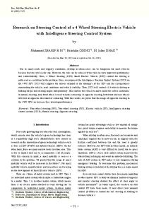
INTERFACE COMPONENTS • A) GMOS-100 Interface • B) 4-pin to 4-pin resistor pad harness • C) 22-pin to 30-pin GMLAN29 harness • D) 22-pin to 30-pin GMLAN11 harness • E) 22-pin to 24-pin CLASS II harness • F) 16-pin Backup camera harness (GMLAN29 vehicles only) • G) 16-pin RSE harness (GMLAN29 vehicles only) • H) 16-pin with stripped leads • I) Female 3.5mm connector with Brown and Brown/White wires
C
D
G
H
E
I
TOOLS REQUIRED • Cutting tool • Crimping tool • Tape • Connectors (example: butt-connectors, bell caps, etc.) M4
ISO
M3.5
IGNITION TERMINALS
M2.6
M3
6 2.5
WIRE CUTTER
1.5
M5
METRA. THE WORLD’S BEST KITS.™ metraonline.com
1-800-221-0932
© COPYRIGHT 2004-2011 METRA ELECTRONICS CORPORATION
INSTGMOS-100
F
B
REV. 8/13/2012
A
GMOS-100
Applications BUICK Allure Enclave Century Lacrosse Lucerne Rainier Rendezvous Terraza
2005-2009 2008-up 2004-2005 2005-2009 2006-2011 2004-2007 2002-2007 2005-2008
CADILLAC SRX Escalade DTS
2007-2009 2003-up 2006-2011
CHEVROLET Avalanche Cavalier Cobalt Corvette Equinox Express Impala Malibu Monte Carlo Silverado SSR Suburban Tahoe Trailblazer Traverse Uplander HHR
2003-up 2000-2005 2007-2010 2005-up 2007-2009 2003-up 2000-up 2001-2012 2000-2007 2003-up 2003-2006 2003-up 2003-up 2002-2009 2009-up 2005-2008 2006-2011
GMC Acadia Envoy Savanna
2007-up 2002-2009 2003-up
GMC (continued) Sierra Yukon/XL/Denali
2003-up 2003-up
HUMMER H2 H3
2003-2009 2006-2009
ISUZU Ascender I Series
2003-2008 2006-2008
OLDSMOBILE Alero Bravada Intrigue Silhouette
2001-2004 2002-2004 2002 2000-2004
PONTIAC Aztec G5 G6 Grand Am Grand Prix Solstice Sunfire Torrent
2001-2005 2007-2008 2009-2010 2001-2005 2004-2008 2006-2009 2000-2005 2007-2009
SAAB 9-7x
2005-2009
SATURN Aura Outlook Sky Relay Vue
2006-2009 2007-2009 2006-2009 2005-2007 2008-2009
SUZUKI 9-7x
2007-2009
Caution: Metra recommends disconnecting the negative battery terminal before beginning any installation. All accessories, switches, and especially air bag indicator lights must be plugged in before reconnecting the battery or cycling the ignition. Note: Refer also to the instructions included with the aftermarket radio.
GMOS-100
Table of Contents Section 1: GM LAN 29 ..................................................................................................... 1.0 – From the 16-pin harness ............................................................................................... 1.1 – From the 22-way harness.............................................................................................. 1.2 – From the 30-way harness (amplified/non-amplified) ...................................................... 1.2 – Installing the GMOS-100 ............................................................................................... 1.3 – Video and RSE harness .................................................................................................. 1.4 – OE Satellite.................................................................................................................... 1.4 Section 2: GM LAN 11 ..................................................................................................... 2.0 – From the 16-pin harness ............................................................................................... 2.1 – From the 22-way harness.............................................................................................. 2.2 – From the 30-way harness (amplified/non-amplified) ...................................................... 2.2 – Installing the GMOS-100 ............................................................................................... 2.3 – Programming the SWC .................................................................................................. 2.4 Section 3: Class II ........................................................................................................... 3.0 – From the 16-pin harness ............................................................................................... 3.1 – From the 22-way harness.............................................................................................. 3.2 – From the 24-way harness (amplified/non-amplified) ................................................3.2-3.3 – From the 12-way harness.............................................................................................. 3.3 – Installing the GMOS-100 ............................................................................................... 3.3 – Programming the SWC .................................................................................................. 3.4 Section 4 ......................................................................................................................... 4.0 – Testing the GMOS-100 .................................................................................................. 4.0 – OnStar Level Adjustment ............................................................................................... 4.1 – Chime Volume Adjustment ............................................................................................. 4.1 – Audio Volume Adjustment .............................................................................................. 4.1 Section 5 ......................................................................................................................... 5.0 – Manually setting the radio type ...................................................................................... 5.0 – Remapping the SWC button .....................................................................................5.1-5.2 – Setting or Forcing Auto Learn on the SWC...................................................................... 5.2
GMOS-100
Section 1: GM LAN 29 BUICK Enclave Lucerne
2008-up 2006-2011
CADILLAC SRX Escalade DTS
2007-2009 2007-up 2006-2011
CHEVROLET Avalanche Equinox Express Impala Monte Carlo Silverado (new body) Suburban Tahoe Traverse
2007-up 2007-2009 2008-up 2006-up 2006-2007 2007-up 2007-up 2007-up 2009-up
GMC Acadia Savanna Sierra (new body) Yukon/XL/Denali
2007-up 2008-up 2007-up 2007-up
HUMMER H2
2003-2009
PONTIAC Torrent
2007-2009
SATURN Outlook Vue
2007-2009 2008-2009
SUZUKI XL-7
2007-2009
1.0
Section 1: GM LAN 29
Connections to be made 1. From the 16-pin harness: •
Connect the Red wires to the ignition/accessory wire of the aftermarket radio.
•
Connect the Orange/White wire to the illumination wire of the aftermarket radio. If the aftermarket radio has no illumination wire, tape off the Orange/White wire.
•
Connect the Blue/White wire to the amp turn on wire of the aftermarket radio.
•
Connect the Brown wire to the mute wire of the aftermarket radio. If the aftermarket radio does not have a Mute wire, tape up the Brown wire.
•
Connect the White wire to the left front positive speaker output of the aftermarket radio.
•
Connect the White/Black wire to the left front negative speaker output of the aftermarket radio.
•
Connect the Gray wire to the right front positive speaker output of the aftermarket radio.
•
Connect the Gray/Black wire to the right front negative speaker output of the aftermarket radio.
•
The Violet wire is not used in the application.
•
The Violet/Black wire is not used in the application.
•
The Green wire is not used in the application.
•
The Green/Black wire is not used in the application.
The following wires are for the aftermarket radios that have navigation built in: •
Connect the Light Green wire to the parking brake wire of the aftermarket navigation radio.
•
Connect the Blue/Pink wire to the VSS or speed sense wire of the aftermarket navigation radio.
•
Connect the Green/Purple wire to the reverse wire of the aftermarket navigation radio.
Continue on next page
1.1
Section 1: GM LAN 29
Connections to be made 2. From the 22-way harness: Connect the 3.5mm jack to the aftermarket radio’s steering wheel control (SWC) input (if equipped). Note: If using Eclipse, Kenwood, or select JVC radios use the supplied female 3.5mm adaptor.
• For Kenwood and select JVC radios: Connect the SWC wire (normally Blue/ Yellow) to the Brown wire of the ASWC. Isolate and tape the Brown/White wire, it will not be used. Some of the newer Kenwood radios will auto detect as a JVC. If this is the case, you can use a 12k ohm resistor (included) in line between the Blue/Yellow and Brown wire of the female 3.5mm jack during programming only. Or you can manually set the radio type which is in the radio programming section of this manual.
• For Eclipse radios: Connect the Eclipse SWC wires (Normally Brown and Brown/ Black) to the Brown and Brown/White wires of the ASWC. Brown goes to Brown and Brown/White goes to Brown/Black. Sometimes this is reversed, so reverse the wires if needed.
• For Metra OE radios: Connect the SWC Key 1 wire (Gray) to the Brown wire of the ASWC female 3.5 adapter. • For all other radios, plug in the male 3.5mm connector of the ASWC into the back of the aftermarket radio, designated for an external SWC control interface. Please refer to the aftermarket radios manual if you are in doubt where the 3.5mm connector of the ASWC goes. • The Black/Yellow wire will be discussed later on in the instructions.
3. From the 30-way harness: • Connect the Black wire to the ground wire of the aftermarket radio. • Connect the RCA to the AUX-in on the aftermarket radio (if equipped). • Satellite information will be displayed on driver information center (DIC). • Connect the Yellow wire to the constant wire of the aftermarket radio. • If the vehicle is amplified disconnect the 4-pin harness located between the 30-way and 22-way connector and connect the supplied 4-pin to 4-pin resistor pad.
Continue on next page
1.2
Section 1: GM LAN 29
Connections to be made For amplified systems: • Connect the Violet wire to the right rear positive wire of the aftermarket radio. • Connect the Violet/Black wire to the right rear negative wire of the aftermarket radio. • Connect the Green wire to the left rear positive wire of the aftermarket radio. • Connect the Green/Black wire to the left rear negative wire of the aftermarket radio. For non-amplified systems: • Cut the resistors from the Green, Green/Black, Purple, Purple/Black right below the heat shrink. • Connect the Violet wire to the right rear positive wire of the aftermarket radio. • Connect the Violet/Black wire to the right rear negative wire of the aftermarket radio. • Connect the Green wire to the left rear positive wire of the aftermarket radio. • Connect the Green/Black wire to the left rear negative wire of the aftermarket radio. • The DIN plug is not used in this application.
Installing the GMOS-100 1. With all the connections completed, plug the 22 and 16-pin harnesses into the GMOS-100. 2. Plug the 30-pin GM harness into the vehicle side harness, and plug the aftermarket radio harness into the aftermarket radio. 3. Reconnect the negative battery terminal. 4. Initialize the interface by cycling the key by (1) turning the ignition “on” for 30 seconds, (2) then back off, and then (3) back on again to test the radio. Doing this will also program the internal ASWC.
1.3
Section 1: GM LAN 29
Video and RSE harness These two additional harnesses are to be used in GMLAN29 systems only. (1) Backup camera harness: • Connect the Yellow RCA to the aftermarket radios backup camera video input. (2) RSE harness: • Connect the “From rear A/V input” RCA to the aftermarket radios audio/video input. Plug Yellow in to video in, Red to right audio in, and White to left audio in. • Connect the “To overhead screen” RCA to the aftermarket radios audio/video output. Plug Yellow in to video out, Red to right audio out, and White to left audio out. • Connect the Black wire with the ring terminal to ground.
OE Satellite (if equipped) • To listen to the factory satellite, change the source of the radio to AUX. • Press and hold the “Source” button for three seconds. • The driver’s information center, located in the center of your instrument cluster, will now display your satellite information. • To exit Satellite mode press and hold “Source” for (3) seconds. Listed below are the functions of the steering wheel controls:
Source - Changes source of the radio/enters and exits Satellite mode Track up - Changes track on radio/satellite station Track down - Changes track on radio/satellite station Volume up - Enter Continued onto Sections 4 and 5
1.4
Notes
GMOS-100
Section 2: GM LAN 11 CHEVROLET Cobalt HHR Malibu
2007-2010 2006-2011 2008-2012
PONTIAC G5 G6 Solstice
2007-2009 2009-2010 2006-2009
SATURN Aura Sky
2.0
2007-2009 2007-2009
Section 2: GM LAN 11
Connections to be made 1. From the 16-pin harness: •
Connect the Red wires to the ignition/accessory wire of the aftermarket radio.
•
Connect the Orange/White wire to the illumination wire of the aftermarket radio. If the aftermarket radio has no illumination wire, tape off the Orange/White wire.
•
Connect the Blue/White wire to the amp turn on wire of the aftermarket radio.
•
Connect the Brown wire to the mute wire of the aftermarket radio. If the aftermarket radio does not have a Mute wire, tape up the Brown wire.
•
Connect the White wire to the left front positive speaker output of the aftermarket radio.
•
Connect the White/Black wire to the left front negative speaker output of the aftermarket radio.
•
Connect the Gray wire to the right front positive speaker output of the aftermarket radio.
•
Connect the Gray/Black wire to the right front negative speaker output of the aftermarket radio.
•
The Violet wire is not used in the application.
•
The Violet/Black wire is not used in the application.
•
The Green wire is not used in the application.
•
The Green/Black wire is not used in the application.
The following wires are for the aftermarket radios that have navigation built in: •
Connect the Light Green wire to the parking brake wire of the aftermarket navigation radio.
•
Connect the Blue/Pink wire to the VSS or speed sense wire of the aftermarket navigation radio.
•
Connect the Green/Purple wire to the reverse wire of the aftermarket navigation radio.
Continue on next page
2.1
Section 2: GM LAN 11
Connections to be made 2. From the 22-way harness: Connect the 3.5mm jack to the aftermarket radio’s steering wheel control (SWC) input (if equipped). Note: If using Eclipse, Kenwood, or select JVC radios use the supplied female 3.5mm adaptor.
• For Kenwood and select JVC radios: Connect the SWC wire (normally Blue/ Yellow) to the Brown wire of the ASWC. Isolate and tape the Brown/White wire, it will not be used. Some of the newer Kenwood radios will auto detect as a JVC. If this is the case, you can use a 12k ohm resistor (included) in line between the Blue/Yellow and Brown wire of the female 3.5mm jack during programming only. Or you can manually set the radio type which is in the radio programming section of this manual.
• For Eclipse radios: Connect the Eclipse SWC wires (Normally Brown and Brown/ Black) to the Brown and Brown/White wires of the ASWC. Brown goes to Brown and Brown/White goes to Brown/Black. Sometimes this is reversed, so reverse the wires if needed.
• For Metra OE radios: Connect the SWC Key 1 wire (Gray) to the Brown wire of the ASWC female 3.5 adapter. • For all other radios, plug in the male 3.5mm connector of the ASWC into the back of the aftermarket radio, designated for an external SWC control interface. Please refer to the aftermarket radios manual if you are in doubt where the 3.5mm connector of the ASWC goes. • The Black/Yellow wire will be discussed later on in the instructions.
3. From the 30-way harness: • Connect the Black wire to the ground wire of the aftermarket radio. • Connect the RCA to the AUX-in on the aftermarket radio (if equipped). • Satellite information will be displayed on driver information center (DIC). • Connect the Yellow wire to the constant wire of the aftermarket radio. • If the vehicle is amplified disconnect the 4-pin harness located between the 30-way and 22-way connector and connect the supplied 4-pin to 4-pin resistor pad.
Continue on next page
2.2
Section 2: GM LAN 11
Connections to be made For amplified systems: • Connect the Violet wire to the right rear positive wire of the aftermarket radio. • Connect the Violet/Black wire to the right rear negative wire of the aftermarket radio. • Connect the Green wire to the left rear positive wire of the aftermarket radio. • Connect the Green/Black wire to the left rear negative wire of the aftermarket radio. For non-amplified systems: • Cut the resistors from the Green, Green/Black, Purple, Purple/Black right below the heat shrink. • Connect the Violet wire to the right rear positive wire of the aftermarket radio. • Connect the Violet/Black wire to the right rear negative wire of the aftermarket radio. • Connect the Green wire to the left rear positive wire of the aftermarket radio. • Connect the Green/Black wire to the left rear negative wire of the aftermarket radio. • The DIN plug is to be connected to the optional XIA-LCD screen if satellite is being retained.
Installing the GMOS-100 1. With all the connections completed, plug the 16 and 22-pin harnesses into the GMOS-100. 2. Plug the 30-pin GM harness into the vehicle side harness, and plug the aftermarket radio harness into the aftermarket radio. 3. Reconnect the negative battery terminal. 4. Initialize the interface by cycling the key by (1) turning the ignition “on” for 30 seconds, (2) then back off, and then (3) back on again to test the radio. Doing this will also program the internal ASWC.
2.3
Section 2: GM LAN 11
Programming SWC 1.
Turn on the ignition.
2.
Turn on the radio.
3.
The LED on the GMOS-100 will turn on solid.
4.
The following buttons must be pressed in the following order: • Volume Up, Seek Up, Band, PTT/Mute, Fan Up (each button pressed will be acknowledged with the LED on steadily). • If any of the above buttons are not present, substitute with Volume Up. For example, if a vehicle does not Band and Fan Up, you would press Volume Up, Seek Up, Volume Up, PTT/MUTE, Volume Up. • After you have pressed five buttons, the LED will turn off. • If you press the buttons incorrectly, turn off the ignition and repeat the above steps. If done incorrectly it can be done again by pressing the “Volume Up” button for 15 seconds until the LED goes into fast blink mode again.
Continued onto Sections 4 and 5
2.4
Notes
GMOS-100
Section 3: Class II BUICK Allure Century Lacrosse Rainier Rendezvous Terraza
2005-2009 2004-2005 2005-2009 2004-2007 2002-2007 2005-2008
CADILLAC Escalade Escalade EXT
2003-2006 2003-2006
CHEVROLET Avalanche Cavalier Corvette Express Impala Malibu Classic Monte Carlo Silverado Silverado Classic SSR Suburban Tahoe Trailblazer Uplander
2003-2006 2000-2005 2005-up 2003-2007 2000-2005 2004 2000-2005 2003-2006 2007 2003-2006 2003-2006 2003-2006 2002-2009 2005-2008
GMC Envoy Savanna Sierra Sierra Classic Yukon/XL/Denali
2002-2009 2003-2007 2003-2006 2007 2003-2006
HUMMER H2 H3
2003-2007 2006-2009
ISUZU Ascender I Series
2003-2008 2006-2008
OLDSMOBILE Alero Bravada Intrigue Silhouette
2001-2004 2002-2004 2002 2000-2004
PONTIAC Aztec Grand Am Grand Prix Sunfire
2001-2005 2001-2005 2004-2008 2000-2005
SAAB 9-7x
2005-2009
SATURN Relay
2005-2007
3.0
Section 3: Class II
Connections to be made 1. From the 16-pin harness: •
Connect the Red wires to the ignition/accessory wire of the aftermarket radio.
•
Connect the Orange/White wire to the illumination wire of the aftermarket radio. If the aftermarket radio has no illumination wire, tape off the Orange/White wire.
•
Connect the Blue/White wire to the amp turn on wire of the aftermarket radio.
•
Connect the Brown wire to the mute wire of the aftermarket radio. If the aftermarket radio does not have a Mute wire, tape up the Brown wire.
•
Connect the White wire to the left front positive speaker output of the aftermarket radio.
•
Connect the White/Black wire to the left front negative speaker output of the aftermarket radio.
•
Connect the Gray wire to the right front positive speaker output of the aftermarket radio.
•
Connect the Gray/Black wire to the right front negative speaker output of the aftermarket radio.
•
The Violet wire is not used in the application.
•
The Violet/Black wire is not used in the application.
•
The Green wire is not used in the application.
•
The Green/Black wire is not used in the application.
The following wires are for the aftermarket radios that have navigation built in: •
Connect the Light Green wire to the parking brake wire of the aftermarket navigation radio.
•
Connect the Blue/Pink wire to the VSS or speed sense wire of the aftermarket navigation radio.
•
Connect the Green/Purple wire to the reverse wire of the aftermarket navigation radio.
Continue on next page
3.1
Section 3: Class II
Connections to be made 2. From the 22-way harness: Connect the 3.5mm jack to the aftermarket radio’s steering wheel control (SWC) input (if equipped). Note: If using Eclipse, Kenwood, or select JVC radios use the supplied female 3.5mm adaptor.
• For Kenwood and select JVC radios: Connect the SWC wire (normally Blue/ Yellow) to the Brown wire of the ASWC. Isolate and tape the Brown/White wire, it will not be used. Some of the newer Kenwood radios will auto detect as a JVC. If this is the case, you can use a 12k ohm resistor (included) in line between the Blue/Yellow and Brown wire of the female 3.5mm jack during programming only. Or you can manually set the radio type which is in the radio programming section of this manual.
• For Eclipse radios: Connect the Eclipse SWC wires (Normally Brown and Brown/ Black) to the Brown and Brown/White wires of the ASWC. Brown goes to Brown and Brown/White goes to Brown/Black. Sometimes this is reversed, so reverse the wires if needed.
• For Metra OE radios: Connect the SWC Key 1 wire (Gray) to the Brown wire of the ASWC female 3.5 adapter. • For all other radios, plug in the male 3.5mm connector of the ASWC into the back of the aftermarket radio, designated for an external SWC control interface. Please refer to the aftermarket radios manual if you are in doubt where the 3.5mm connector of the ASWC goes. • The Black/Yellow wire will be discussed later on in the instructions.
3. From the 24-way harness: • Connect the Black wire to the ground wire of the aftermarket radio. • Connect the Yellow wire to the constant wire of the aftermarket radio. • If the vehicle is amplified disconnect the 4-pin harness located between the 30-way and 22-way connector and connect the supplied 4-pin to 4-pin resistor pad. If the vehicle is not amplified connect the two 4-pins for the 30 and 22-way together. For amplified systems: • Connect the Violet wire to the right rear positive wire of the aftermarket radio. Continue on next page
3.2
Section 3: Class II
Connections to be made • Connect the Violet/Black wire to the right rear negative wire of the aftermarket radio. • Connect the Green wire to the left rear positive wire of the aftermarket radio. • Connect the Green/Black wire to the left rear negative wire of the aftermarket radio. For non-amplified systems: • Cut the resistors from the Green, Green/Black, Purple, Purple/Black right below the heat shrink. • Connect the Violet wire to the right rear positive wire of the aftermarket radio. • Connect the Violet/Black wire to the right rear negative wire of the aftermarket radio. • Connect the Green wire to the left rear positive wire of the aftermarket radio. • Connect the Green/Black wire to the left rear negative wire of the aftermarket radio. • The DIN plug is to be connected to the optional XIA-LCD screen if satellite or RSE is being retained. 4. From the 12-way harness: • Connect the Blue/Pink wire to the aftermarket radios VSS (if populated on factory side). • Connect the RCA to the AUX in on the aftermarket radio (if equipped).
Installing the GMOS-100 1. With all the connections completed, plug the 24, 22, and 12-pin harnesses into the GMOS-100. 2. Plug the 24 and 12-pin GM harness into the vehicle side harness, and plug the aftermarket radio harness into the aftermarket radio. 3. Reconnect the negative battery terminal. Cycle the key by turning the ignition on for 30 seconds, then back off, then back on again to test the radio.
3.3
Section 3: Class II
Programming SWC In Class II vehicles, there are two-ways to program the SWC. If your vehicle is not on the following list please refer to the “All Other Vehicle” section. BUICK Rainier
2004-2007
CADILLAC Escalade (all models)
2003-2006
CHEVROLET Avalanche Cavalier Silverado Silverado Classic SSR Suburban Tahoe Trailblazer
2003-up 2000-2005 2003-2006 2007 2003-2006 2003-2006 2003-up 2002-2009
GMC Envoy Sierra
2002-2009 2003-2006
1. 2. 3. 4. 5.
GMC continued Sierra Classic Yukon (all models)
2007 2003-2006
HUMMER H2
2003-2007
ISUZU Ascender
2003-2008
OLDSMOBILE Bravada
2002-2004
PONTIAC Sunfire
2000-2005
SAAB 9-7x
2005-2009
Turn on the ignition. Turn on the radio. The LED on the GMOS-100 will begin to blink rapidly. Turn on the aftermarket radio. Tap “Volume Up” until radio responses.
All Other Vehicles 1) Turn “on” the ignition. 2) The LED will go on solid. The following buttons must be pressed in order: • Volume Up, Seek Up, Band, PTT/Mute, Fan Up (each button pressed will be acknowledged with the LED on steadily). • If any of the above buttons are not present, substitute with Volume Up. For example, if a vehicle does not Band and Fan Up, you would press Volume Up, Seek Up, Volume Up, PTT/MUTE, Volume Up. • After you have pressed all five buttons, the LED will turn “off”. Continued onto Sections 4 and 5
3.4
Notes
GMOS-100
Section 4 GMOS-100
Testing the GMOS-100 •
Turn the ignition “on”. Then turn the aftermarket radio “on”.
•
Press the OnStar button, the radio should turn “off” (radio will mute if mute wire is connected) and you should hear OnStar.
•
Push the OnStar cancel button and the radio should come back “on”.
Continue on next page
4.0
Section 4
OnStar Level Adjustment •
To adjust the OnStar volume level find the Black/Yellow wire on the 16-pin harness.
•
Push the blue OnStar button, while the voice is speaking tap the Black/Yellow wire to ground.
•
Once the volume is set it will stay at that volume until the Black/Yellow wire is tapped to the ground again. This can be set during installation and then left alone. If adjustment is desired, the user may also tap “Volume Up” or “Down” on the steering wheel (if equipped) to adjust the OnStar level.
Chime Volume Adjustment 1)
With car on, shut off car and leave keys in ignition. Open the car door and leave it open. Chimes will be heard.
2)
Wait 10 seconds, then with a small screwdriver adjust the potentiometer fully counterclockwise (all the-way left), then clockwise to raise chime level and counterclockwise to lower the chime level.
3)
When the volume is at the desired level, remove the keys from the ignition. This will lock the chime volume at its current level.
Audio Volume Adjustment 1)
Start your vehicle and turn on the radio having audio playing.
2)
Turn your aftermarket radio’s volume up ¾ of the-way.
3)
With a small screwdriver adjust the potentiometer clockwise to raise the audio level and counterclockwise to lower the audio level.
4)
Once at desired level your audio adjustment is complete.
4.1
GMOS-100
Section 5 GMOS-100
Manually setting the radio type: If the LED flashes do not match the radio you have connected, you must manually program the ASWC to tell it what radio it is connected to. 1. To manually program the aftermarket radio turn “on” the ignition. Then press and hold the “Volume Down” button on the steering wheel control until the LED goes solid red and then release the “Volume Up” button. 2. Using the listing below press the “Volume Up” button the number of times (number is to the left of the radio name) needed to program the correct radio type: 1 2 3 4 5 6
Eclipse Kenwood Clarion “Type 1” Sony/Dual JVC Jensen/Pioneer
7 8 9 10 11
Alpine Visteon Valor Clarion “Type 2” Metra OE
3. Press and hold the “Volume Down” button for 5 seconds to finish programming. The LED will then go off. 4. After a few seconds, the LED will then blink the number of times corresponding to the radio type. This number should be the same number that the “Volume Up” button had been pressed. Continue on next page
5.0
Section 5
Remapping the SWC button Let’s say you have the GMOS-100 programmed to your vehicle and your radio and you want to change the button assignment for the steering wheel controls. For instance, if you would like the “Seek Up” button to be assigned as “Mute”. Note, before beginning: • The GMOS-100 must have detected the vehicle and radio it is attached to before you can remap any buttons. • You can only start the remapping of the steering wheel controls process after 20 seconds of turning the ignition key “on”. If you wait longer than the 30 seconds you will have to turn the ignition off then back on again. • Within the first 20 seconds if any button other then “Volume Up” or “Volume Down” is pushed, the remapping process will stop. • If during the remapping process no button is pushed for 30 seconds the remapping process is aborted and the original settings are reset. Now let’s begin the remapping process: 1.
Ideally having the GMOS-100 visible is recommended since you can see the LED flashes to confirm button recognition.
2.
Turning off the radio is recommended.
3.
After 20 seconds of turning the ignition “on” press and hold down the “Volume Up” button for at least 25 seconds.
4.
The LED will light up solid red. Release “Volume Up” and the LED will go out. “Volume Up” has now been programmed.
5.
Next, continue the process of remapping buttons to the SWC in order of the list below. 1 2 3 4 5 6
Volume Up Volume Down Seek Up/Next Seek Down/Prev Source/Mode Mute
7 8 9 10 11 12
Preset Up Preset Down Power Band Play/Enter PTT (Push To Talk)
13 14 15 16 17 18
On Hook Off Hook Fan Up Fan Down Temp Up Temp Down
If you want to skip a command press the “Volume Up” on the steering wheel, this will tell the GMOS-100 to skip the command and go to the next one.
5.1
Section 5
Remapping the SWC Button Note: Not all radios will have all of these commands. Please refer to the radio’s owners manual for specific commands recognized by that radio. For instance, the next command to be mapped is the “Volume Down” command. Let’s say you want the “Mode” button on your steering wheel to be the “Volume Down” command. Hold down the “Mode” button till the LED lights up solid red and then release it. Now the “Mode” button on the steering wheel is “Volume Down”. 6.
After the last button is programmed on your steering wheel (you do not have to go through the whole list), hold down the “Volume Up” button for at least 10 seconds then the LED will go out. ----- OR ----After the 18th button is programmed and/or skipped the LED will go out and remapping is completed. If after remapping the SWC and you want to revert the SWC back to its original settings follow these steps below: Resetting or Forcing Auto Learn on the SWC 1) Within the first 20 seconds of turning the ignition on. Press and hold down the original “Volume Up” button for at least 25 seconds. 2) The LED will blink rapidly. 3) Release the “Volume Up” button and wait until the LED goes on solid. 4) After the LED goes off the original steering wheel control settings will be restored.
5.2
Notes
GMOS-100
Section 6 GMOS-100
XIA-LCD Screen (optional) If the tuner is separate the XIA-LCD will allow you to view the factory installed SYNC or satellite information.
5
1
3
2 4
1. 2. 3. 4. 5.
Channel Up: Allows “Channel Up” function in satellite mode. Channel Down: Allows “Channel Down” function in satellite mode. Select/Enter button: Selects current item on screen. Escape/Exit button: Exits to previous screen. Screen: This is where your satellite/SYNC information is viewed.
6.0
Notes
Notes
Notes
INSTALLATION INSTRUCTIONS FOR PART GMOS-100
IMPORTANT WARNING This product includes instructions for installation which must be carefully followed. The instructions are worded in such a manner to assume that the installer is capable of completing these type of electronic installations. If you are unclear as to what you are instructed to do or believe that you do not understand the instructions so as to properly and safely complete the installation you should consult a technician who does have this knowledge and understanding. Failure to follow these instructions carefully and to install the interface as described could cause harm to the vehicle or to safety systems on the vehicle. Interference with certain safety systems could cause harm to persons as well. If you have any questions in this regard please call the Help line or Metra at 1-800-221-0932 for assistance.
KNOWLEDGE IS POWER
Metra recommends MECP certified technicians
REV. 8/13/2012
INSTGMOS-100
Enhance your installation and fabrication skills by enrolling in the most recognized and respected mobile electronics school in our industry. Log onto www.installerinstitute.com or call 800-354-6782 for more information and take steps toward a better tomorrow.
METRA. THE WORLD’S BEST KITS.™ metraonline.com
1-800-221-0932
© COPYRIGHT 2004-2011 METRA ELECTRONICS CORPORATION
INSTGMOS-100
INSTRUCCIONES DE INSTALACIÓN PARA LA PIEZA GMOS-100
ADVERTENCIA IMPORTANTE Este producto incluye instrucciones de instalación que deben seguirse cuidadosamente. Dichas instrucciones están redactadas dando por supuesto que el instalador es capaz de completar estos tipos de instalaciones electrónicas. Si tiene dudas respecto de lo que se le indica que haga o cree que no comprende las instrucciones como para completar la instalación en forma adecuada y segura, debe consultar a un técnico que efectivamente tenga estos conocimientos y comprensión. Si no sigue estas instrucciones con cuidado y no instala la interfaz como se describe, podría provocar daños en el vehículo o en los sistemas de seguridad del vehículo. La interferencia con determinados sistemas de seguridad también podría provocar daños a las personas. Si tiene alguna pregunta al respecto, llame a la línea de ayuda o a metra, al 1-800-221-0932 para obtener asistencia.
CONOCIMIENTO PODER KEL NOWLEDGE IS PES OWER
Enhance fabrication yskills by Mejoreyour sus installation habilidadesand de instalación fabricación enrolling in the most recognized and respected inscribiéndose en la escuela de dispositivos mobile electronics school in our industry. electrónicos móviles más reconocida y respetada de Log onto www.installerinstitute.com or call nuestra industria. Regístrese en www.installerinstitute. 800-354-6782 for more information and take steps toward tomorrow. com oa better llame al 800-354-6782 para obtener más
información y avance hacia un futuro mejor.
Metra recomienda técnicos con certificación del Programa de Certificación en Electrónica Móvil (Mobile Electronics Certification Program, MECP).
REV. 8/29/2012
METRA. THE WORLD’S BEST KITS.™ metraonline.com
1-800-221-0932
© COPYRIGHT 2004-2011 METRA ELECTRONICS CORPORATION
Notas
Notas
Notas
GMOS-100
Sección 6 GMOS-100
La pantalla XIA-LCD (opcional) Si el sintonizador está separado del XIA-LCD le permitirá ver el SYNC instalado de fábrica o información de satélite.
5
1
3
2 4
1. Channel Up (Canal hacia arriba): Permite usar la función de cambio de canal hacia arriba en modo satelital. 2. Channel Down (Canal hacia abajo): Cambiar canal hacia abajo: Permite usar la función de cambio de canal hacia abajo en modo satelital 3. Select/Enter (Selección/Aceptar): Selecciona el elemento que está actualmente en pantalla. 4. Escape/Exit (Escape/Salida): Sale a la pantalla anterior. 5. Screen (Pantalla): Aquí es donde se visualiza su información satelital.
6.0
Notas
6.
Sección 5
Remapping the SWC Button Nota: Recuerde que no todos los radios tienen estos comandos. Consulte el manual del propietario del radio para los comandos específicos reconocidos por el radio. Por ejemplo, el siguiente comando a mapear es el comando de bajar volumen. Digamos que usted quiere que el botón Modo de su volante sea el botón para bajar el volumen. Mantenga presionado el botón Modo hasta que el foco LED se ilumine en rojo sin parpadear, luego suéltelo. Ahora el botón de Modo de su volante es el botón para bajar el volumen. Después de programar el último botón en su volante (no tiene que pasar por toda la lista), mantenga presionado el botón de aumentar volumen durante al menos 10 segundos y el foco LED se apagará. ----- O bien ----Después de que programe o se salte el botón número 18, el foco LED se apagará y el remapeo habrá terminado. Si por algún motivo después de remapear los controles del volante quiere volver a los ajustes originales del volante, siga estos pasos: Cómo restablecer o forzar el aprendizaje automático en el SWC 1) En los primeros 20 segundos después de encender la ignición Presione y mantenga presionado el botón original de aumento de volumen durante 25 segundos, cuando menos. 2) El foco LED parpadeará rápidamente. 3) Suelte el botón de aumentar volumen y espere hasta que el foco LED se encienda sin parpadear. 4) Después de que el foco LED se apague, los ajustes originales del control del volante se restablecerán.
5.2
Sección 5
Remapeo de los botones SWC Digamos que tiene el GMOS-100 programado para su vehículo y su radio y ahora quiere cambiar la asignación de los botones para los controles del volante. Por ejemplo, le gustaría que el botón de buscar siguiente funcionara como silencio. Nota, antes de comenzar: • El GMOS-100 debe haber detectado el vehículo y radio conectado antes de que se puedan remapear los botones. • Solo podrá iniciar el proceso de remapeo de los controles del volante dentro de los primeros 20 segundos después de abrir la llave de la ignición. Si espera más de 30 segundos, tendrá que apagar la ignición y volver a encenderla. • En los primeros 20 segundos, si se presiona cualquier botón que no sea el de subir o bajar volumen, el proceso de remapeo se detendrá. • Si durante el proceso de remapeo no se presiona ningún botón durante 30 segundos, el proceso de remapeo se aborta y se restablecen los ajustes originales. Now let’s begin the remapping process:
Next, continuar con el proceso de remapeo el SWC en el orden de la lista de abajo:
5.
El foco LED se iluminará en rojo sin parpadear. Suelte el botón de aumentar volumen y el foco LED se apagará. Ya quedó programado el botón que sube el volumen.
4.
Dentro de los primeros 20 segundos después de encender la ignición, presione y mantenga presionado el botón de aumentar volumen durante cuando menos 25 segundos.
3.
Se recomienda apagar el radio.
2.
Idealmente se recomienda tener el GMOS-100 visible, puesto que se puede ver el parpadeo del foco LED para confirmar el reconocimiento de los botones.
1.
1 2 3 4 5 6
Volume Up Volume Down Seek Up/Next Seek Down/Prev Source/Mode Mute
7 8 9 10 11 12
Preset Up Preset Down Power Band Play/Enter PTT (Push To Talk)
13 14 15 16 17 18
On Hook Off Hook Fan Up Fan Down Temp Up Temp Down
Por ejemplo, si desea omitir un comando presione el botón “Volume Up” (Subir volumen) en el volante, este le dirá al GMOS-100 para omitir el comando e ir a la siguiente.
5.1
GMOS-100
Sección 5 GMOS-100
Para configurar manualmente el tipo de radio: Si el parpadeo del foco LED no corresponde al radio que tiene conectado, debe programar manualmente el ASWC para indicar a cuál radio está conectado. 1. Para programar manualmente el radio de mercado secundario, encienda la ignición, presione y mantenga presionado el botón de bajar volumen en el control del volante hasta que el foco LED se quede en rojo sin parpadear, luego suelte el botón de aumentar volumen. 2. Presione el botón de aumentar volumen la cantidad de veces necesarias para programar el tipo de radio. 1 2 3 4 5 6
Eclipse Kenwood Clarion “Type 1” Sony/Dual JVC Jensen/Pioneer
7 8 9 10 11
Alpine Visteon Valor Clarion “Type 2” Metra OE
3. Presione y mantenga presionado el botón de bajar volumen durante 5 segundos para terminar la programación. El foco LED se apagará. 4. Después de unos cuantos segundos, el foco LED parpadeará la cantidad de veces correspondiente al tipo de radio. Este número debe ser igual que el número de veces que el usuario ha presionado el botón de aumentar volumen. Continúa en la página
5.0
Sección 4
Ajuste del nivel de OnStar
Una vez configurado el volumen, permanecerá a ese nivel hasta que el cable Negro/ Amarillo vuelva a tocarse a tierra.
•
Presione el botón azul de OnStar y mientras la voz esté hablando, toque el cable Negro/Amarillo a tierra.
•
Para ajustar el nivel del volumen de OnStar, busque el cable Negro/Amarillo en el arnés de 16-pin.
•
Esto puede ajustarse durante la instalación y después ignorarse. Si se desea que el usuario pueda hacer ajustes, el cliente también puede pulsar el botón que sube o baja el volumen desde el volante (si está equipado) para ajustar el nivel de OnStar.
Ajuste del volumen de los tonos
Cuando el volumen esté en el nivel deseado, retire las llaves de la ignición. Esto bloqueará el volumen de los tonos en su nivel actual.
3)
Espere 10 segundos, luego con un pequeño destornillador, ajuste el potenciómetro por completo hacia la izquierda (a la izquierda hasta topar), luego hacia la derecha para subir el nivel de los tonos y hacia la izquierda para bajar el nivel de los tonos.
2)
Con el vehículo encendido, apague el auto y deje las llaves en la ignición. Abra la puerta del carro y déjela abierta. Se escucharán tonos.
1)
Ajuste del nivel de audio
Una vez que haya llegado al nivel deseado, su ajuste de audio está completo.
4)
Con un pequeño destornillador, ajuste el potenciómetro hacia la derecha para aumentar el nivel de audio y hacia la izquierda para disminuir el nivel de audio.
3)
Aumente el volumen del radio de mercado secundario hasta llegar a ¾ del máximo nivel.
2)
Arranque su vehículo y encienda el radio mientras reproduce audio.
1)
4.1
GMOS-100
Sección 4 GMOS-100
Prueba del GMOS-100
Presione el botón de cancelación de Onstar y el radio debe volver a escucharse.
•
Presione el botón Onstar, el radio debe apagarse (el radio se quedará en silencio si el cable de silencio está conectado) y usted debe escuchar a Onstar.
•
Abra la llave y luego encienda el radio de mercado secundario.
•
Continúa en la página
4.0
Notas
Sección 3: Class II
Programación de SWC En los vehículos Clase II, hay dos formas de programar el SWC. Si su vehículo no está en la siguiente lista, consulte la sección “Todos los demás vehículos”.
2002-2009 2003-2006
GMC Envoy Sierra
2003 y mas 2000-2005 2003-2006 2007 2003-2006 2003-2006 2003 y mas 2002-2009
CHEVROLET Avalanche Cavalier Silverado Silverado Classic SSR Suburban Tahoe Trailblazer
2003-2006
CADILLAC Escalade (all models)
2004-2007
BUICK Rainier
1. 2. 3. 4. 5.
GMC continued Sierra Classic Yukon (all models)
2007 2003-2006
2005-2009
SAAB 9-7x
2000-2005
PONTIAC Sunfire
2002-2004
OLDSMOBILE Bravada
2003-2008
ISUZU Ascender
2003-2007
HUMMER H2
Encienda la ignición. Encienda el radio. El foco LED del GMOS-100 empezará a parpadear rápidamente. Encienda el radio de mercado secundario. Toque el botón para aumentar el volumen hasta que el radio responda.
All Other Vehicles 1) Encienda la ignición. 2) El foco LED se encenderá sin parpadear. Debe presionar los siguientes botones en el siguiente orden: • Subir volumen, buscar siguiente, banda, PTT/silencio, aumentar ventilador (cada vez que presione el botón el foco LED se iluminará sin parpadear). • Si cualquiera de estos botones no está presente, utilice el botón de subir volumen. Por ejemplo, si un vehículo no tiene los botones de banda y aumentar ventilador, usted presionaría los botones de subir volumen, buscar siguiente, subir volumen, PPT/ silencio, subir volumen. • Después de haber presionado los cinco botones, el foco LED se apagará. Continúa en la Seccións 4 y 5
3.4
Sección 3: Class II
Conexiones que se deben hacer • Conecte el cable Verde al cable positivo posterior izquierdo del radio de mercado secundario. • Conecte el cable Verde/Negro al cable negativo posterior izquierdo del radio de mercado secundario. Vehículos no amplificados: • Corte las resistencias de los cables Verde, Verde/Negro, Violeta, Violeta/Negro justo debajo del termoencogimiento. • Conecte el cable Violeta al cable positivo posterior derecho del radio de mercado secundario. • Conecte el cable Violeta/Negro al cable negativo posterior derecho del radio de mercado secundario. • Conecte el cable Verde al cable positivo posterior izquierdo del radio de mercado secundario. • Conecte el cable Verde/Negro al cable negativo posterior izquierdo del radio de mercado secundario. • El conector DIN debe conectarse a la pantalla opcional XIA-LCD si se desea retener el satélite o RSE. 4. From the 12-way harness: • Conecte el cable azul/rosa al VSS del radio de mercado secundario (si está poblado de fábrica). • Conecte los conectores RCA a la entrada AUX del radio de mercado secundario (si se incluye).
Instalación del GMOS-100 1. Cuando termine todas las conexiones, conecte los arneses de 24, 22 y 12-pin al GMOS-100. 2. Conecte el arnés GM de 24 y 12-pin en el arnés lateral del vehículo y conecte el arnés del radio de mercado secundario en el radio de mercado secundario. 3. Reconecte la terminal de la batería negativa. Cicle la llave prendiendo la ignición durante 30 segundos, luego apáguela y préndala otra vez para probar el radio.
3.3
Sección 3: Class II
Conexiones que se deben hacer 2. Desde el arnés de 22 vías: Conecte el conector de 3.5mm a la entrada de control del volante de su radio de mercado secundario (si cuenta con dicho equipamiento). Nota: Si usa un radio Eclipse, Kenwood o algunos radios JVC, use el adaptador hembra de 3.5 suministrado. • Para radios Kenwood y algunos JVC: Conecte el cable SWC (normalmente azul/amarillo) al cable marrón del ASWC. Aísle y encinte el cable marrón/blanco, no se utilizará. Algunos de los radios Kenwood más nuevos se detectarán automáticamente como JVC. Si este es el caso, puede usar una resistencia de 12k ohmios (incluida) en línea entre el cable azul/amarillo y marrón del conector hembra de 3.5mm durante la programación únicamente. O puede configurar manualmente el tipo de radio que está en la sección de programación de este manual.
• Para radios Eclipse: Conecte los cables SWC del Eclipse (normalmente marrón y marrón/negro) a los cables marrón y marrón/blanco del ASWC. Marrón va con marrón y marrón/blanco va con marrón/negro. En ocasiones esto es al revés; invierta los cables si se necesita. • Para radios Metra OE: Conecte el cable SWC Clave 1 (gris) al cable marrón del adaptador hembra de 3.5 de ASWC. • For all other radios, conecte el conector macho de 3.5mm del ASWC en la parte posterior del radio de mercado secundario, designada para una interfase de control externo SWC. Consulte el manual del radio de mercado secundario si tiene dudas acerca de dónde debe ir el conector 3.5mm. • El cable Negro/Amarillo se explicará más adelante en las instrucciones.
3. From the 24-way harness: • Conecte el cable Negro con el cable de conexión a tierra del radio de mercado secundario. • Conecte el cable Amarillo con el cable constante del radio de mercado secundario. • Si el vehículo está amplificado, desconecte el arnés de 4-pin localizado entre el conector de 30 vías y de 22 vías y conecte el cojinete suministrado de resistencia de 4-pin a 4-pin. Si el vehículo no está amplificado, conecte juntos los dos arneses de 4-pin para el conector de 30 y 22 vías. Vehículos amplificados: • Conecte el cable Violeta al cable positivo posterior derecho del radio de mercado secundario. • Conecte el cable Violeta/Negro al cable negativo posterior derecho del radio de mercado secundario. Continúa en la página
3.2
Sección 3: Class II
Conexiones que se deben hacer 1. Desde el arnés de 16-pin:
El cable Verde/Negro no se utiliza en la aplicación.
•
El cable Verde no se utiliza en la aplicación.
•
El cable Violeta/Negro no se utiliza en la aplicación.
•
El cable Violeta no se utiliza en la aplicación.
•
Conecte el cable Gris/Negro con la salida de la bocina negativa frontal derecha del radio de mercado secundario.
•
Conecte el cable Gris con la salida de la bocina positiva frontal derecha del radio de mercado secundario.
•
Conecte el cable Blanco/Negro con la salida de la bocina negativa frontal izquierda del radio de mercado secundario.
•
Conecte el cable Blanco con la salida de la bocina positiva frontal izquierda del radio de mercado secundario.
•
Conecte el cable Marrón con el cable de silencio del radio de mercado secundario. Si el radio de mercado secundario no tiene un cable de silencio, encinte el cable Marrón.
•
Conecte el cable Azul/Blanco con el cable de encendido del amplificador del radio de mercado secundario.
•
Conecte el cable Anaranjado/Blanco al cable de iluminación del radio de mercado secundario. Si el radio de mercado secundario no tiene cable de iluminación, cubra con cinta el cable Anaranjado/Blanco.
•
Conecte los cables Rojos al cable de ignición/accesorio del radio de mercado secundario.
•
Los siguientes cables son para radios de mercado secundario que tienen navegación integrada:
Conecte el cable Verde/Púrpura al cable de reversa del radio con navegación de mercado secundario.
•
Conecte el cable Azul/Rosa con el cable VSS o de detección de velocidad del radio de navegación de mercado secundario.
•
Conecte el cable Verde claro con el cable del freno de mano del radio de navegación de mercado secundario.
•
Continúa en la página
3.1
GMOS-100
Sección 3: Class II
2003-2006 2000-2005 2005 y mas 2003-2007 2000-2005 2004 2000-2005 2003-2006 2007 2003-2006 2003-2006 2003-2006 2002-2009 2005-2008
CHEVROLET Avalanche Cavalier Corvette Express Impala Malibu Classic Monte Carlo Silverado Silverado Classic SSR Suburban Tahoe Trailblazer Uplander
2003-2006 2003-2006
CADILLAC Escalade Escalade EXT
2005-2009 2004-2005 2005-2009 2004-2007 2002-2007 2005-2008
BUICK Allure Century Lacrosse Rainier Rendezvous Terraza
GMC Envoy Savanna Sierra Sierra Classic Yukon/XL/Denali HUMMER H2 H3
2002-2009 2003-2007 2003-2006 2007 2003-2006 2003-2007 2006-2009
2005-2007
SATURN Relay
2005-2009
SAAB 9-7x
2001-2005 2001-2005 2004-2008 2000-2005
PONTIAC Aztec Grand Am Grand Prix Sunfire
2001-2004 2002-2004 2002 2000-2004
OLDSMOBILE Alero Bravada Intrigue Silhouette
2003-2008 2006-2008
ISUZU Ascender I Series
3.0
Notas
Sección 2: GM LAN 11
Programación de SWC
Debe presionar los siguientes botones en el siguiente orden:
4.
El foco LED del GMOS-100 se encenderá sin parpadear.
3.
Encienda el radio.
2.
Encienda la ignición.
1.
• Subir volumen (Volume Up), buscar siguiente (Seek Up), banda (Band), PTT/silencio (PTT/Mute), aumentar ventilador (Fan Up). Cada vez que presione el botón el foco LED se iluminará sin parpadear. • Si alguno de estos botones no está presente, utilice el botón de subir volumen. Por ejemplo, si un vehículo no tiene los botones de banda y aumentar ventilador, usted presionaría los botones de subir volumen, buscar siguiente, subir volumen, PPT/ silencio, subir volumen. • Después de haber presionado los cinco botones, el foco LED se apagará. • Si presiona los botones incorrectamente, apague la ignición y repita los pasos anteriores. Si se equivoca, puede volver a hacerlo presionando el botón de aumentar volumen durante 15 segundos hasta que el foco LED entre de nuevo en modo de parpadeo rápido.
Continúa en la Seccións 4 y 5
2.4
Sección 2: GM LAN 11
Conexiones que se deben hacer Vehículos amplificados: • Conecte el cable Violeta al cable positivo posterior derecho del radio de mercado secundario. • Conecte el cable Violeta/negro al cable negativo posterior derecho del radio de mercado secundario. • Conecte el cable Verde al cable positivo posterior izquierdo del radio de mercado secundario. • Conecte el cable Verde/Negro al cable negativo posterior izquierdo del radio de mercado secundario. Vehículos no amplificados: • Corte las resistencias de los cables Verde, Verde/Negro, Púrpura, Púrpura/Negro justo debajo del termoencogimiento. • Conecte el cable Violeta al cable positivo posterior derecho del radio de mercado secundario. • Conecte el cable Violeta/Negro al cable negativo posterior derecho del radio de mercado secundario. • Conecte el cable Verde al cable positivo posterior izquierdo del radio de mercado secundario. • Conecte el cable Verde/Negro al cable negativo posterior izquierdo del radio de mercado secundario. • El conector DIN debe conectarse a la pantalla opcional XIA-LCD si se desea retener el satélite.
Instalación del GMOS-100 1. Cuando termine todas las conexiones, conecte los arneses de 22 y 16-pin al GMOS-100. 2. Conecte el arnés GM de 30-pin en el arnés lateral del vehículo y conecte el arnés del radio de mercado secundario en el radio de mercado secundario. 3. Reconecte la terminal de la batería negativa. 4. Inicialice la interfase ciclando la llave prendiendo la ignición durante 30 segundos, luego apáguela y préndala otra vez para probar el radio. Hacer esto también programará el ASWC interno.
2.3
Sección 2: GM LAN 11
Conexiones que se deben hacer 2. Desde el arnés de 22 vías: Conecte el conector de 3.5mm a la entrada de control del volante de su radio de mercado secundario (si cuenta con dicho equipamiento). Nota: Si usa un radio Eclipse, Kenwood o algunos radios JVC, use el adaptador hembra de 3.5 suministrado.
• Para radios Metra OE: Conecte el cable SWC Clave 1 (gris) al cable marrón del adaptador hembra de 3.5 de ASWC.
• Para radios Eclipse: Conecte los cables SWC del Eclipse (normalmente marrón y marrón/negro) a los cables marrón y marrón/blanco del ASWC. Marrón va con marrón y marrón/blanco va con marrón/negro. En ocasiones esto es al revés; invierta los cables si se necesita.
• Para radios Kenwood y algunos JVC: Conecte el cable SWC (normalmente azul/amarillo) al cable marrón del ASWC. Aísle y encinte el cable marrón/blanco, no se utilizará. Algunos de los radios Kenwood más nuevos se detectarán automáticamente como JVC. Si este es el caso, puede usar una resistencia de 12k ohmios (incluida) en línea entre el cable azul/amarillo y marrón del conector hembra de 3.5mm durante la programación únicamente. O puede configurar manualmente el tipo de radio que está en la sección de programación de este manual.
• For all other radios, conecte el conector macho de 3.5mm del ASWC en la parte posterior del radio de mercado secundario, designada para una interfase de control externo SWC. Consulte el manual del radio de mercado secundario si tiene dudas acerca de dónde debe ir el conector 3.5mm. • El cable Negro/Amarillo se explicará más adelante en las instrucciones. 3. Desde el arnés de 30 vías: • • • • •
Conecte el cable Negro con el cable de conexión a tierra del radio de mercado secundario. Conecte los conectores RCA a la entrada AUX del radio de mercado secundario (si se incluye). La información de satélite se mostrará en el D.I.C. Conecte el cable Amarillo con el cable constante del radio de mercado secundario. Si el vehículo está amplificado, desconecte el arnés de 4-pin localizado entre el conector de 30 vías y de 22 vías y conecte el cojinete suministrado de resistencia de 4-pin a 4-pin.
Continúa en la página
2.2
Sección 2: GM LAN 11
Conexiones que se deben hacer 1. Desde el arnés de 16-pin:
El cable Verde/Negro no se utiliza en la aplicación.
•
El cable Verde no se utiliza en la aplicación.
•
El cable Violeta/Negro no se utiliza en la aplicación.
•
El cable Violeta no se utiliza en la aplicación.
•
Conecte el cable Gris/Negro con la salida de la bocina negativa frontal derecha del radio de mercado secundario.
•
Conecte el cable Gris con la salida de la bocina positiva frontal derecha del radio de mercado secundario.
•
Conecte el cable Blanco/Negro con la salida de la bocina negativa frontal izquierda del radio de mercado secundario.
•
Conecte el cable Blanco con la salida de la bocina positiva frontal izquierda del radio de mercado secundario.
•
Conecte el cable Marrón con el cable de silencio del radio de mercado secundario. Si el radio de mercado secundario no tiene un cable de silencio, encinte el cable Marrón.
•
Conecte el cable Azul/Blanco con el cable de encendido del amplificador del radio de mercado secundario.
•
Conecte el cable Anaranjado/Blanco al cable de iluminación del radio de mercado secundario. Si el radio de mercado secundario no tiene cable de iluminación, cubra con cinta el cable Anaranjado/Blanco.
•
Conecte los cables Rojos al cable de ignición/accesorio del radio de mercado secundario.
•
Los siguientes cables son para radios de mercado secundario que tienen navegación integrada:
Conecte el cable Verde/Púrpura al cable de reversa del radio con navegación de mercado secundario.
•
Conecte el cable Azul/Rosa con el cable VSS o de detección de velocidad del radio de navegación de mercado secundario.
•
Conecte el cable Verde claro con el cable del freno de mano del radio de navegación de mercado secundario.
•
Continúa en la página
2.1
GMOS-100
Sección 2: GM LAN 11
2007-2009 2009-2010 2006-2009
PONTIAC G5 G6 Solstice
2007-2010 2006-2011 2008-2012
CHEVROLET Cobalt HHR Malibu
SATURN Aura Sky
2007-2009 2007-2009
2.0
Notas
Sección 1: GM LAN 29
Arnés de video y RSE Estos dos arneses adicionales deben usarse únicamente en los sistemas gmlan29. (1) Arnés de cámara de reversa: • Conecte el conector RCA Amarillo a la entrada de video de la cámara de reversa del radio de mercado secundario. (2) Arnés de RSE: • Conecte los conectores RCA “De la entrada trasera A/V” a la entrada de audio/ video del radio de mercado secundario. Conecte el conector amarillo de entrada a la entrada de video, el rojo a la entrada de audio derecha y el blanco a la entrada de audio izquierda. • Conecte los conectores RCA “A la pantalla de techo” a la salida de audio/video del radio de mercado secundario. Conecte el conector amarillo a la salida de video, el rojo a la salida de audio derecha y el blanco a la salida de audio izquierda. • Conecte el cable negro con la terminal de aro a tierra.
Satélite de fabricante original
(si se incluye)
• Para escuchar el satélite de fábrica, cambie al fuente del radio a AUX. • Presione y mantenga presionado el botón “Source” (Fuente) durante tres segundos. • El centro de información del conductor, localizado en el centro de su conjunto de instrumentos, ahora mostrará su información de satélite. • Para salir del modo de satélite, presione y mantenga presionado “Source” (Fuente) durante (3) segundos. A continuación se enumeran las funciones de los controles del volante:
Source (Fuente) - Cambia la fuente Track Up (Track arriba) - Cambia la pista Track Down (Track abajo) - Cambia la pista Volume Up (Aumentar volumen) - Entrar Continúa en la Seccións 4 y 5
1.4
Sección 1: GM LAN 29
Conexiones que se deben hacer Vehículos amplificados: • Conecte el cable Violeta al cable positivo posterior derecho del radio de mercado secundario. • Conecte el cable Violeta/negro al cable negativo posterior derecho del radio de mercado secundario. • Conecte el cable Verde al cable positivo posterior izquierdo del radio de mercado secundario. • Conecte el cable Verde/Negro al cable negativo posterior izquierdo del radio de mercado secundario. Vehículos no amplificados: • Corte las resistencias de los cables Verde, Verde/Negro, Púrpura, Púrpura/Negro justo debajo del termoencogimiento. • Conecte el cable Violeta al cable positivo posterior derecho del radio de mercado secundario. • Conecte el cable Violeta/Negro al cable negativo posterior derecho del radio de mercado secundario. • Conecte el cable Verde al cable positivo posterior izquierdo del radio de mercado secundario. • Conecte el cable Verde/Negro al cable negativo posterior izquierdo del radio de mercado secundario. • El conector DIN no se utiliza en esta aplicación
Instalación del GMOS-100 1. Cuando termine todas las conexiones, conecte los arneses de 22 y 16-pin al GMOS-100. 2. Conecte el arnés GM de 30-pin en el arnés lateral del vehículo y conecte el arnés del radio de mercado secundario en el radio de mercado secundario. 3. Reconecte la terminal de la batería negativa. 4. Inicialice la interfase ciclando la llave prendiendo la ignición durante 30 segundos, luego apáguela y préndala otra vez para probar el radio. Hacer esto también programará el ASWC interno.
1.3
Sección 1: GM LAN 29
Conexiones que se deben hacer 2. Desde el arnés de 22 vías: Conecte el conector de 3.5mm a la entrada de control del volante de su radio de mercado secundario (si cuenta con dicho equipamiento). Nota: Si usa un radio Eclipse, Kenwood o algunos radios JVC, use el adaptador hembra de 3.5 suministrado.
• Para radios Metra OE: Conecte el cable SWC Clave 1 (gris) al cable marrón del adaptador hembra de 3.5 de ASWC.
• Para radios Eclipse: Conecte los cables SWC del Eclipse (normalmente marrón y marrón/negro) a los cables marrón y marrón/blanco del ASWC. Marrón va con marrón y marrón/blanco va con marrón/negro. En ocasiones esto es al revés; invierta los cables si se necesita.
• Para radios Kenwood y algunos JVC: Conecte el cable SWC (normalmente azul/amarillo) al cable marrón del ASWC. Aísle y encinte el cable marrón/blanco, no se utilizará. Algunos de los radios Kenwood más nuevos se detectarán automáticamente como JVC. Si este es el caso, puede usar una resistencia de 12k ohmios (incluida) en línea entre el cable azul/amarillo y marrón del conector hembra de 3.5mm durante la programación únicamente. O puede configurar manualmente el tipo de radio que está en la sección de programación de este manual.
• For all other radios, conecte el conector macho de 3.5mm del ASWC en la parte posterior del radio de mercado secundario, designada para una interfase de control externo SWC. Consulte el manual del radio de mercado secundario si tiene dudas acerca de dónde debe ir el conector 3.5mm. • El cable Negro/Amarillo se explicará más adelante en las instrucciones.. 3. Desde el arnés de 30 vías: • • • • •
Conecte el cable Negro con el cable de conexión a tierra del radio de mercado secundario. Conecte los conectores RCA a la entrada AUX del radio de mercado secundario (si se incluye). La información de satélite se mostrará en el D.I.C. Conecte el cable Amarillo con el cable constante del radio de mercado secundario. Si el vehículo está amplificado, desconecte el arnés de 4-pin localizado entre el conector de 30 vías y de 22 vías y conecte el cojinete suministrado de resistencia de 4-pin a 4-pin.
Continúa en la página
1.2
Sección 1: GM LAN 29
Conexiones que se deben hacer 1. Desde el arnés de 16-pin:
El cable Verde/Negro no se utiliza en la aplicación.
•
El cable Verde no se utiliza en la aplicación.
•
El cable Violeta/Negro no se utiliza en la aplicación.
•
El cable Violeta no se utiliza en la aplicación.
•
Conecte el cable Gris/Negro con la salida de la bocina negativa frontal derecha del radio de mercado secundario.
•
Conecte el cable Gris con la salida de la bocina positiva frontal derecha del radio de mercado secundario.
•
Conecte el cable Blanco/Negro con la salida de la bocina negativa frontal izquierda del radio de mercado secundario.
•
Conecte el cable Blanco con la salida de la bocina positiva frontal izquierda del radio de mercado secundario.
•
Conecte el cable Marrón con el cable de silencio del radio de mercado secundario. Si el radio de mercado secundario no tiene un cable de silencio, encinte el cable Marrón.
•
Conecte el cable Azul/Blanco con el cable de encendido del amplificador del radio de mercado secundario.
•
Conecte el cable Anaranjado/Blanco al cable de iluminación del radio de mercado secundario. Si el radio de mercado secundario no tiene cable de iluminación, cubra con cinta el cable Anaranjado/Blanco.
•
Conecte los cables Rojos al cable de ignición/accesorio del radio de mercado secundario.
•
Los siguientes cables son para radios de mercado secundario que tienen navegación integrada:
Conecte el cable Verde/Púrpura al cable de reversa del radio con navegación de mercado secundario.
•
Conecte el cable Azul/Rosa con el cable VSS o de detección de velocidad del radio de navegación de mercado secundario.
•
Conecte el cable Verde claro con el cable del freno de mano del radio de navegación de mercado secundario.
•
Continúa en la página
1.1
GMOS-100
Sección 1: GM LAN 29
2007 y mas 2007-2009 2008 y mas 2006 y mas 2006-2007 2007 y mas 2007 y mas 2007 y mas 2009 y mas
CHEVROLET Avalanche Equinox Express Impala Monte Carlo Silverado (cuerpo nuevo) Suburban Tahoe Traverse
2007-2009 2007 y mas 2006-2011
CADILLAC SRX Escalade DTS
2008 y mas 2006-2011
BUICK Enclave Lucerne
2003-2009
HUMMER H2
2007 y mas 2008 y mas 2007 y mas 2007 y mas
GMC Acadia Savanna Sierra (cuerpo nuevo) Yukon/XL/Denali
2007-2009
SUZUKI XL-7
2007-2009 2008-2009
SATURN Outlook Vue
2007-2009
PONTIAC Torrent
1.0
GMOS-100
Indice Sección 1: GM LAN 29 .................................................................................................... 1.0 – Desde el arnés de 16-pin .............................................................................................. 1.1 – Desde el arnés de 22 vías ............................................................................................. 1.2 – Desde el arnés de 30 vías (amplificados/no amplificados) ............................................. 1.2 – Instalación del GMOS-100 ............................................................................................. 1.3 – Video and RSE harness .................................................................................................. 1.4 – OE Satellite.................................................................................................................... 1.4 Sección 2: GM LAN 11 .................................................................................................... 2.0 – Desde el arnés de 16-pin .............................................................................................. 2.1 – Desde el arnés de 22 vías ............................................................................................. 2.2 – Desde el arnés de 30 vías (amplificados/no amplificados) ............................................. 2.2 – Instalación del GMOS-100 ............................................................................................. 2.3 – Programación de SWC ................................................................................................... 2.4 Sección 3: Class II .......................................................................................................... 3.0 – Desde el arnés de 16-pin .............................................................................................. 3.1 – Desde el arnés de 22 vías ............................................................................................. 3.2 – From the 24-way harness (amplificados/no amplificados)........................................3.2-3.3 – From the 12-way harness.............................................................................................. 3.3 – Instalación del GMOS-100 ............................................................................................. 3.3 – Programación de SWC ................................................................................................... 3.4 Sección 4......................................................................................................................... 4.0 – Prueba del GMOS-100 ................................................................................................... 4.0 – Ajuste del nivel de OnStar.............................................................................................. 4.1 – Ajuste del volumen de los tonos .................................................................................... 4.1 – Ajuste del nivel de audio ................................................................................................ 4.1 Sección 5......................................................................................................................... 5.0 – Para configurar manualmente el tipo de radio................................................................ 5.0 – Remapeo de los botones SWC .................................................................................5.1-5.2 – Cómo restablecer o forzar el aprendizaje automático en el SWC .................................... 5.2
GMOS-100
Aplicaciones
2007 y mas 2002-2009 2003 y mas
GMC Acadia Envoy Savanna
2003 y mas 2000-2005 2007-2010 2005 y mas 2007-2009 2003 y mas 2000 y mas 2001-2012 2000-2007 2003 y mas 2003-2006 2003 y mas 2003 y mas 2002-2009 2009 y mas 2005-2008 2006-2011
CHEVROLET Avalanche Cavalier Cobalt Corvette Equinox Express Impala Malibu Monte Carlo Silverado SSR Suburban Tahoe Trailblazer Traverse Uplander HHR
2007-2009 2003 y mas 2006-2011
CADILLAC SRX Escalade DTS
2005-2009 2008 y mas 2004-2005 2005-2009 2006-2011 2004-2007 2002-2007 2005-2008
BUICK Allure Enclave Century Lacrosse Lucerne Rainier Rendezvous Terraza
2007-2009
SUZUKI 9-7x
2006-2009 2007-2009 2006-2009 2005-2007 2008-2009
SATURN Aura Outlook Sky Relay Vue
2005-2009
SAAB 9-7x
2001-2005 2007-2008 2009-2010 2001-2005 2004-2008 2006-2009 2000-2005 2007-2009
PONTIAC Aztec G5 G6 Grand Am Grand Prix Solstice Sunfire Torrent
2001-2004 2002-2004 2002 2000-2004
OLDSMOBILE Alero Bravada Intrigue Silhouette
2003-2008 2006-2008
ISUZU Ascender I Series
2003-2009 2006-2009
HUMMER H2 H3
2003 y mas 2003 y mas
GMC (seguido) Sierra Yukon/XL/Denali
PRECAUCIÓN: Metra recomienda desconectar el terminal negativo de la batería antes de comenzar cualquier instalación. Todos los accesorios, interruptores y, especialmente, las luces indicadoras de airbag deben estar enchufados antes de volver a conectar la batería o comenzar el ciclo de ignición. Nota: Remítase a las instrucciones incluidas con el radio de postventa.
INSTRUCCIONES DE INSTALACIÓN PARA LA PIEZA GMOS-100
GMOS-100 Interfaz de control en volante para vehículos GM 2000 y más APLICACIONES Ver interior de la portada
CARACTERÍSTICAS DEL KIT • Cubre vehículos Clase 2, LAN 29 y LAN11 • • Proporciona accesorio (12 voltios 10 amperes) • • Retiene R.A.P. (Corriente de accesorio retenida) • • Se usa en sistemas amplificados o no • amplificados • • Retiene todos los tonos de advertencia • • Proporciona salidas de NAV (freno de mano, reversa, silencio y V.S.S.) • • ASWC integrado (interfaz de control en volante) • Retiene OnStar/Bluetooth de fabricante original
Volumen ajustable para tonos y OnStar Entrada de bocina de alto nivel Actualizable a micro “B” USB Retiene el balance y la intensidad Retiene la cámara de reversa de fábrica Retiene RSE (entretenimiento en asiento trasero) Retiene satélite de fabricante original (el vehículo debe tener los controles de volante del fabricante original)
COMPONENTES DE LA INTERFAZ • A) Interfaz GMOS-100 • B) Arnés de cojinete de resistencia de 4-pin a 4-pin • C) Arnés de 22pin a 30-pin GMLAN29 • D) Arnés de 22-pin a 30-pin GMLAN11 • E) Arnés CLASE II de 22-pin a 24-pin • F) Arnés de cámara de reversa de 16-pin (solo vehículos GMLAN29) • G) Arnés RSE de 16-pin (solo vehículos GMLAN29) • H) 16-pin con conectores pelados • I) Conector hembra de 3.5mm con cables marrón y marrón/blanco
A
F
B
C
G
D
H
E INSTGMOS-100
I
HERRAMIENTAS REQUERIDAS • Cortador • Pelacables • Cinta • Conectores (p. ej., conectores a tope, tapas acampanadas, etc.) IGNITION TERMINALS
M4
ISO
M3.5 M2.6
M3
WIRE CUTTER
6 2.5
1.5
M5
REV. 8/29/2012
METRA. THE WORLD’S BEST KITS.™ metraonline.com
1-800-221-0932
© COPYRIGHT 2004-2011 METRA ELECTRONICS CORPORATION