ASM Specialty Handbook: Tool Materials Joseph R. Davis, Editor
Copyright © 1995 ASM International® All rights reserved www.asminternational.org
General Guidelines for Selecting Cutting Tool Materials SELECTING Tiffi PROPER CUTIING TOOL MATERIAL for a specific machining application can provide substantial advantages, including increased productivity, improved quality, and reduced costs (Ref 1). Increased productivity can be obtained by increasing cutting speeds and/or feed rates. Increasing the speeds and feeds, however, is limited by the capability of the cUtting tool material and machine tool. Speeds and feeds must be kept low enough to provide an acceptable tool life. Otherwise, tool changing and grinding costs can outweigh the advantages of faster machining rates by increasing the cost per part produced. Machine tool downtime for replacement of dull or broken tools is a major deterrent to increasing productivity.
Because of the wide range of conditions and requirements, no single cutting tool material meets the needs of all machining applications. Each tool material has its own combination of properties that makes it best for a specific opera~ tion. The fol1owing factors affect the selection of a cutting tool material for a specific application (Ref 1): • Hardness and condition of the workpiece rna~ terial • Operations to be performed (optimum tool se~ lection may reduce the number of operations required) • Amount of stock to be removed • Accuracy and finish requirements
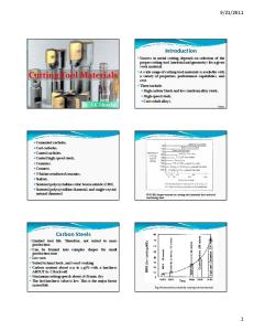
Toughness Abrasion resistance
Transverse rupture strength, MPa (ksi)
Hardness, HRA
l
High-speed 3447-4826 stee I
(500-700)
~6.5 (60-70 HRC)
f---,
l
Cas t 2068-2413 alloy
f-----,
81-84
(300-350)
Taii:65 HRC)
l
Micro grain 2758-3723 carbide
l
91.5-92.0
(400-540) C-1 and C~2 carbide
l
1655-2241
90.0-92.0
l
(240-325) C-3and C4 '1207-1793 carbide
l
92.0-93.0
l
90.0-92.5
I
(175-260) C-5 and C-6 1379-2068 carbide
l
(200-300) C-7 and C-8 689.5-1724 carbide
92.0-95.0
I
(100-250)
e:---.
Ceramic ~-758.4
93.5-94.0
I
(80-110) Polycrystalline diamond ~379
6500·8000 HK
(100-200)
Fig. 1 Comparison of toughness and wear resistance for various cutting tool materials. Source: Metcut Research Associates, Inc.
• TYpe, capability, and condition of the machine tool to be used • Rigidity of the tool and workpiece • Production requirements influencing the speeds and feeds selected • Operating conditions, such as cutting forces and temperatures • Tool cost per part machined, including initial tool cost, grinding cost, tool life, frequency of regrinding or replacement, and labor cost. The most economical tool is not necessarily the one providing the longest life or having the lowest initial cost.
Desirable Properties In evaluating a cutting tool material in a machining operation, the applicability is dependent on having the correct combination of physical prbperties. Because maximizing one property typically means lowering some other property (e.g., extremely wear-resistant materials generally have poor toughness, as shown in Fig. 1), the workpiece properties and cutting operations strongly influence the selection of a cutting tool material. Similarly, developing an understanding of the tool properties and their relationship to cutting performance is the key to understanding the potential application range. Properties of primary concern in cutting tool design are fracture resistance (toughness), plastic or thermal deformation resistance, and wear resistance. Also of concern is the resistance of the material to cracking, notching, cratering, and, in the case of coated inserts, spalling (poor coating adherence). Machine tests have been developed to measure the resistance of cutting tools to these failure mechanisms. This is accomplished by matching the workpiece and tool materials, adjusting machining parameters over the likely application range, and then carefully evaluating the failure modes and their relationship to basic physical properties of materials. Common failure mechanisms are shown in Fig. 2. The cutting tool properties of most concern in evaluating these failures are described below. Additional information on cutting tool failures can be found in the articles
4
I
Materials for Machining and Grinding
"Cemented Carbides" and "Wear and Failure Modes for Cutting Tools" in this Volume. Toughness is commonly defined by cutting tool users as the resistance of the cutting edge to
Predominant failure mechanisms Heavy roughing
breakage or fracture under unfavorable condi-
• • • •
High feed rates Moderate-to-severe interruptions Inconsistent or difficult workpiece material Lack of rigidity
Flank Wear Resistance. The resistance of the cutting tool to flank wear is a primary concern in the applicability of the material to a cutting operation. The tool must have adequate resistance to both abrasive and chemical wear, so the chemical inertness of the material as well as its hardness must be considered. Figure 3(a) shows a typical wear land generated during a turning or facing operation. The balancing of abrasive and chemical wear resistance, along with toughness, gives each tool material family its own application range. Generally, as the cutting speed increases, chemical wear resistance becomes more important. Therefore, inert materials such as oxides and nitrides perform better at higher cutting speeds. Deformation. A secondary effect of high cutting speeds is plastic deformation due to increased cutting temperatures . .Under these conditions, the binder phase of a cemented carbide cutting tool material may soften and deform, causing a bulging effect (Fig. 3b). Such an effect can cause breakage, a higher flank wear rate, or spalling of the coatings. This effect is accentuated under high chip loads and is a typical failure mode for rough cutting, in which the toughness requirements prevent the use of ceramic or other binderless cutting materials. Crater Resistance. A secondary result of abrasive and chemical wear is the formation of a crater on the rake surface of the insert. In this case, the chips formed during the operation rub and weld on the rake face, causing a dish-shaped depression to form (Fig. 3c). As a result of this formation, cutting forces can increase and, coupled with the weakening of the insert, can result in catastrophic failure due to chipping or breakage. Crater formation can be inhibited, however, with the proper chip-breaker geometry. Cracking occurs under heavy mechanical load and/or as a result of rapid and repeated temperature changes during the cutting operation. Cracks typically initiate at high-stress areas and extend parallel or perpendicular to the cutting edge (Fig. 3d). Commonly seen in milling operations, these cracks eventually lead to catastrophic failure due to chipping or breakage. Notching occurs most commonly in the machining of high-temperature materials such as nickel-base superalloys. It arises in a localized area at the depth of cut and is a result of the high stresses in that area. Under these conditions, minor chipping, coupled with an accelerated wear rate, results in a failure of the type shown in Fig. 3(e). As this notch grows, the likelihood of crack formation and subsequent breakage is increased.
Wear land Deformation Crater
Chipping Deformation Cracking Crater
Fracture Chipping Deformation
tions, which typically include one or more of the following:
Semifinishing
Roughing
Increasing feed
\
Finishing Deformation Crater Wear land
Increasing speed
~---------------------t--------------------~
Fig. 2
Predominant failure mechanisms of coated carbides when machining steels
The resistance of whisker-reinforced ceramics to this crack formation is one reason they have been successful in cutting this type of material. Chipping is a less severe and more common form of breakage. If the strength of the cutting tool material is exceeded in localized areas due to chatter, variations in the workpiece, or buildup on the cutting edge, small fragments of the cutting edge break away during the cutting operation (Fig. 3!). Edge preparation plays an important role in minimizing chipping. Ultimately, the intent in targeting application ranges is to avoid fracture of the insert (Fig. 3g). When this occurs, the insert (and often the workpiece) is rendered unusable.
Other alloying elements include tungsten, chromium, vanadium, and cobalt. These steels reach ·exceptionally high hardness after heat treatment and can maintain that hardness at relatively high temperatures. Type T steels also have high carbon contents, with tungsten as the primary alloying element. Chromium and vanadium are present as alloying elements in all type T steels; most also contain cobalt. The tungsten types tend to be less tough, more resistant to heat, and slightly higher in abrasion resistance than type M high-speed steels. Compositions and properties of both types can be found in the articles "Wrought High-Speed Tool Steels" and "Powder Metallurgy High-Speed Tool Steels" in this Volume. When compared with competing cutting tool materials, high-speed steels are characterized by moderate wear resistance and high transverse Cutting Tool Materials rupture strengths (Fig. 1), giving them wide apThe classes of tool materials currently in use plicability on machining operations. Their prifor machining operations are high-speed tool mary limitation is speed/metal removal rate, as steels, cobalt-base alloys, cemented carbides, cer- they typically suffer plastic deformation at relamets, ceramics, polycrystalline cubic boron ni- tively low cutting speeds (30 to 60 rn!min, or 100 tride, and polycrystalline diamond. The different to 200 sfm). As a result, their primary applicamaterials vary greatly in wear resistance and tions are in form cutters, reamers, taps, drills, and toughness. Figure 4 shows schematically their small-diameter end mills. High-speed steels are relative application ranges in terms of machining also used in the milling of high-temperature maspeeds and feed rates. Higher machining speeds terials and on older machines with less rigidity require tool materials with greater wear resis- and limited speed capability. tance, whereas higher feed rates require tools Cobalt-based cutting tools have been availwith increased toughness. High-speed tool steels able since about 1920 (Ref 1). These materials are are the toughest materials; however, their rela- generally cast cobalt-chromium-tungsten alloys tively low wear resistance limits their application with carbon and other alloy additions. They are to lower-speed machining operations. At the not heat treatable, and the maximum hardness (55 other end of the spectrum, ultrahard materials to 65 HRC) occurs near the cast surface. As a such as CBN and PCD are highly wear resistant result, cast alloy tools must be used as-cast with and can be employed at high speeds. However, as little grinding as possible. Cast alloy materials are not widely used. Howthere is a tradeoff between wear resistance and toughness that can limit the application of these ever, they find limited use as a compromise, beultrahard tools to slower feed rates. Figure 5 pro- cause th~y perform well at higher surface speeds vides specific cutting tool recommendations for than conventional high-speed steels and are more machining a variety of ferrous and nonferrous resistant to chipping than standard carbide materials. Manufacturers of cutting tool materials grades. More detailed infonnation on both cast should also be consulted for information on se- and powder metallurgy forms of these alloys can lection criteria of the various grades they pro- be found in the article "Cobalt-Base Alloys" in this Volume. duce. High-Speed Tool Steels. There are two classiCemented carbides belong to a class of hard, fications of high-speed steels: molybdenum high- wear-resistant, refractory materials in which the speed steels (type M) and tungsten high-speed hard carbides of Group IVB-VIB metals are bound together or cemented by a ductile metal steels (type T). l'ype M steels have high carbon contents, with binder, usually cobalt or nickel. The first cemolybdenum as the major alloying element. mented carbide was produced in the 1920s and
Selecting Cutting Tool Materials I 5
(a)
H
(c)
(b)
1 mm
100 J.l.m
H
(d)
1 mm
(e)
1 mm
100 p,m
(g)
(f) 1
mm
1 mm
fig. 3
Failure mechanisms of cutting tools. (a) Typical flank wear on a carbide insert. (b) Typical edge deformation on a carbide insert. (c) Typical crater wear on a carbide insert. (d) Typical perpendicular cracks on a carbide insert. (e) Typical notching at depth of cut on a whisker-reinforced ceramic insert. (f) Typical chipping on a carbide insert. (g) Typical fracture on a carbide insert
consisted of tungsten carbide (WC) with a cobalt binder (Ref2). A remarkable feature of cemented carbides is that they can be tailored to provide different combinations of abrasion resistance and toughness by controlling the amount of cobalt and the we grain size. Over the years, the basic WC-Co material has been modified to produce a variety of cemented carbides containing WC-TiC, WC-TiC-TaC,
WC-TiC-(Ta,Nb)C, and other solid-solution cubic carbides. The commercially significant alloys for machining contain 5 to 12 wt% Co and up to 15 wt% cubic carbides. Carbide grain sizes from 0.5 to 5 Jlm are commonly used. Compositions and properties of these materials are described in the article "Cemented Carbides" in this Volume. Cemented carbides dominate the metal removal market. They possess high wear resistance
and compressive strengths that enable them to cut a wide variety of materials at favorably high material removal rates. Uncoated carbides are typically found in the machining of cast irons, steels, stainless steels, and nonferrous and hightemperature materials at speeds up to 150m/min (500 sfm). Coatings such as titanium nitride (TiN), titanium carbide (TiC), and aluminum oxide (A[z03)
6/ Materials for Machining and Grinding
I
"C Q) Q)
.,c.
~ ~ Ceramics Cermets
Cl
r:::
~
Carbides
(,)
HighSpeed Tool Steels
Cl
c:
"iii
"'~
(,)
c:
increasing feed rate Fig. 4
Relative machining application ranges of various cutting tool materials
were added to enable still-higher metal removal rates to be achieved (Fig. 6). These coatings enhance the wear and crater resistance of cemented carbides with a modest loss in strength. As a result, a major portion of the market in cast iron, steel, and stainless steel machining is served by these materials, with machining speeds up to 275 m/min (900 sfm). More detailed information on coating methods used to extend the life and productivity of cemented carbide inserts can be found in the article "Coated Carbide, Cermet, and Ceramic Tool Materials" in this Volume. Cermets. A cermet is a composite of a ceramic material with a metallic binder. Although WC-Co tools also fit this definition, in the North American machining industry the term cennets is applied more specifically to TiC-based tools that contain mainly nickel as a binder. The first cutting tool in this family, a TiC-Ni alloy, was commercialized as early as the 1930s but could not compete with the inherently stronger WC-Cobased tools. Additions of molybdenum to TiC-Ni alloys in 1960 brought cermets closer in performance to WC-Co-based tools for finish machining of steels. Titanium carbonitride cermets based on Ti(C,N)-Ni-Mo were introduced in 1970, followed by (Ti,Mo)(C,N)-based compositions that provided a balance of wear resistance and toughness due to their finer microstructures (Ref 4). Continued development in this area has resulted in complex cermets having a variety of additives, such as Mo 2C, TaC, ZrC, HfC, we, vc, Cr3c 2, and aluminum (Ref 5). Various mixes of these additives impart different combinations of wear resistance, thermal-shock resistance, and toughness, and they allow tools to be tailored for a wide range of machining applications. The newer cermets are used in semifinishing and finishing of carbon and alloy steels, stainless steels, ductile irons, free-machining aluminum and other nonferrous alloys, and some high-temperature alloys.
The metal removal operations may include turning, boring, milling, threading, and grooving; speeds up to 365 rn!min (1200 sfm) are common. Ceramic tools are inherently more stable than carbide tools at high temperatures (high cutting speeds) but are less fracture resistant, so recent work has focused on improving their fraclure toughness. There are basically two classes of ceramic cutting tools: A)z03-based ceramics and silicon nitride (Si]N4)-based ceramics. The white Ab03-based ceramics may contain low levels of zirconia (Zr02) as a sintcring aid and are used for machining cast iron. Higher Zr02levels are used in tools to machine steels. The Zr02 improves fracture toughness by a transformation toughening or crack deflection mechanism (Ref 6, 7), but it decreases the thermal conductivity and hardness of the tool. Additions of up to 30 val% TiC to Ah03 make the inserts black and improve the thermal conductivity, hardness, and toughness of the tools without seriously degrading their chemical stability. The Ah03-TiC ceramics are employed on a wide range of workpiece materials, including cast iron, steel, and nickel-base superalloys. Silicon carbide (SiC) whisker~reinforced A]z03 (A]z03-SiCw) ceramics, developed in the early 1980s (Ref 8), are tougher than white ceramics due to crack deflection by the dispersed SiC whiskers in the microstructure (Ref 9). The whiskers also increase hardness and improve thermal-shock resistance by increasing thermal conductivity and reducing the thermal expansion coefficient. The major application of these tool materials is high-speed, high-feed machining of nickel-base superalloys. These ceramics can be used on cast irons but are rarely used on steels because of the poor chemical stability of SiC. Tools based on Si3N4 and solid solutions of aluminum and oxygen in Si]N4 (Sialons) were introduced in the early 1980s. Their whisker-like grain structure makes them tougher than the
white Ah03 ceramics, and they also possess exce11ent hot hardness and thermal-shock resistance. These characteristics pennit them to be used at high speeds and feed rates and in interrupted cutting of nickel-base superalloys and cast irons (Ref 10, 11). However, the chemical stability of SbN4/Sialon tool materials is lower than that of alumina ceramics, which prohibits their application in most steel machining. The high hardness and thermal-deformation resistance of ceramic cutting tool materials allow metal removal at speeds as high as 1220 rn!min (4000 sfm). Additional information on the properties and applications of Ah03- and Si3N4-based cutting tool materials can be found in the article "Ceramics" in this Volume. Ultrahard Tool Materials. Cubic boron ni- · tride (CBN) and polycrystalline diamond (PCD) are extremely wear-resistant materials commonly referred to as ultrahard or superhard tool materials. Synthesis, properties, and applications of CBN and PCD are described in the article ..Ultrahard Tool Materials" in this Volume. The use of CBN and PCD as abrasive grains for grinding applications is described in the article ..Abrasives for Grinding Applications" in this Volume. Cubic boron nitride, which has a hardness of 4500 HK, is the material of choice for machining steels with hardnesses exceeding 50 HRC. Other applications include machining of cast irons (typically 180 to 240 HB) and superalloys (>35 HRC). Polycrystalline diamond, on the other hand, cannot be used for steel machining because of its solubility and the catalytic effect of iron, which causes graphitization of the diamond. The primary application of PCD tools is in the veryhigh-speed machining of aluminum-silicon alloys, composites, and other nonmetallic workpieces. Speeds as high as 2000 m!min (6500 sfm) can be achieved during machining of aluminumsilicon alloys with PCD tooling.
Application/Grade Selection Knowledge of the machinability characteristics of the workpiece material and the properties of the cutting tool material is the starting point for selecting a grade-geometry combination for any machining operation. The task of the tooling engineer is to select, from the vast numbers of possibilities, the grade that will give the best performance, predictability, reliability, and cost. To accomplish this, it is necess&ry to evaluate the operation characteristics, insert and chip groove selection criteria, and machining economics (Ref 12).
Operation Characteristics The operation category involves determining whether heavy roughing, roughing, semifinishing, or finishing is needed. For example, the high-speed finishing of steel requires high wear and deformation resistance. Coated grades, cermets, and ceramics are candidates fm: this type of operation.
Selecting Cutting Tool Materials I 7
= ,,,,,,,,d
Alz03-based ceramics may be more economical.
Speed attainable when cutting free-machining and/or nonferrous materials
Surface finish, part geometry, and part tolerance should also be considered. For example,
Typical speed range Occasional usage
Speed, sfm
Generally
successful
100 Rough,
PCO
semifinish, finish
Rough, semifinish, finish
Silicon nitride {SiAION)
Rough, semifinish, finish
Rough, semifinish, finish
Rough, semifinish, finish
Rough, semifinish, finish
Rough, semifinish, finish
Semifinish,
finish
0
30
60
120
180
245
305
610
915
Aluminum, high-silicon aiolminwnl alloys, nonferrous,
nonmetallic
Gray, ductile, malleable irons
High-temperature hard steels, cast irons
Irons, steels, powdered metals
Irons and steels, above 40 HAC, pearlitic gray irons below 30 HAC
Irons, steels, high-temperature
alloys, stainless steels
Irons, steels, stainless steels
Irons, steels, stainless steels
Rough, semifinish, finish
Irons, steels, nickel-base, stainlesi? steels
Rough, iii finish
Irons, steels, titanium, high-temperature alloys, stainless steels
Heavy rough, semifinish
Irons, steels, stainless steels
Rough, semifinish, finish
Irons, steels, high-temperature alloys, stainless steels
coated carbide inserts generally produce a better surface finish than uncoated carbides. Machine capabilities and limitations are the final operation characteristics that must be determined. For example, older machines with poor rigidity and low horsepower cannot make effective use of advanced ceramic materials, and highspeed tool steels are generally recommended.
Insert and Chip Groove Selection A variety of insert shapes, sizes, nose radii, and chip grooves are available for any machining operation. Proper selection is essential to optimize the operation for productivity and cost. The shape of an insert determines its relative strength and cost (Fig. 7). In general, the stronger insert has more available cutting edges and therefore can be more economical on a cost-per-index basis. However, the part geometry may limit the use of the desired insert shape. The general rule is to select the strongest insert capable of producing the required part configuration. Size and Nose Radii. The size of an insert is detennined by the inscribed circle. The depth of cut should not exceed one-half the inscribed circle size, and the insert thickness should be at least four times the operating feed rate. Finally, the largest possible nose radius should be selected. Larger radii produce better surface finishes, handle heavier feed rates, and strengthen the insert. Chip groove selection is almost as crucial as selecting the proper grade. The performance of the cutting tool is determined not only by the grade properties and coating type but also by a chip groove style that will allow lower cutting forces, better chip handling and control, extended tool life, and lower machining costs. Modem numerically controlled machining operations put a high demand on reliable chip flow. Long chips cause ihterruptions of the machining cycle, a loss of productivity, and damage to the cutting tool and workpiece. Long chips also represent a personal hazard to the operator. Commercially available inserts with chip grooves are designed to produce acceptable chips throughout the widest possible range of feed rates and depths of cut while maintaining high edge strength. General recommendations are listed below for proper chip groove selection on carbide tools:
1220 1525 1830 2135 2440
• For general-purpose applications, select a
Speed, m/min
Fig. 5 Approximate speed ranges and applications of various cutting and tool materials. Source: GTE Valenite Corp. Workpiece material type (hard, soft and gummy, or difficult to machine) must also be determined. For example, the machining of soft and gummy low-carbon steel at moderate speeds requires a TiN -coated insert or a cermet to resist buildup at the cutting edge and to provide a good surface finish.
Production volume (large or small scale, periodic or long-range production) is a third important consideration. For example, the machining of difficult-to-cut Inconel 718 in largescale production using whisker-reinforced ceramics will increase productivity and lower cost. In small-scale production, conventional
chip groove that has its nominal feed range as near as possible to the intended operating feed rate. This will ensure acceptable chips, predictable and reliable tool life, and a lower cost per index. • For heavy feeds/high material-removal rates, select single-sided inserts. The improved rigidity and resultant higher effective edge strength permit higher speeds and feeds while generating lower forces than double-sided inserts. In most cases, this will improve productivity.
8 I Materials for Machining and Grinding 1000
Table 1 Different types of ceramic edge preparation with recommended application
BOO
Al~:rcoated
Operation
600
0
~
General purpose Finishing General purpose and milling Heavy roughing Special
400
'"•••
0. ~
Rake angle
Chamfer
Negative Negative or positive Negative Negative Negative or positive
0.20 mm X 20° (0.008 in. X 20°) 0.075 mmx25° (0.003 in.x25°) 0.15mmx 30°(0.006 in x30°) 0.38mmx25°(0.Q15 in. x25°) Special
Width
~ u
200
IL
Width
IJ::__t
~~ngle ~"Angle
I }'
100
1
R•dou'
I ,A I
2 Tool life, min to 0.25 mm flank wear
Special applications, fine finishing
(a)
General-purpose grades, higher forces, negative rake angles
1000 600 400 200
.0
.€ E -o
100
••0.
60