COM-5404
GbE IP GATEWAY ROUTER
Key Features
The COM-5404 is a layer 3 IP router which acts as gateway between a gigabit Ethernet (GbE) LAN and a digital clock-synchronous link to/from a remote WAN IP frames can be forwarded and received as 8-bit parallel or 1-bit serial data streams A CRC is attached to each transmitted IP frame for error detection at the receiving end 1-bit serial streams are HDLC encoded and scrambled IP offload engine (all IP protocols implemented in FPGA/VHDL) for maximum throughput performance and very low latency. Maximum throughput 950 Mbits/s (8-bit parallel interface) or 120 Mbits/s (1-bit serial interface) Complies with IPv4 routers specifications RFC1812 Built-in DHCP server automatically assigns IP addresses to local IP clients, for ease of network management Built-in DHCP client can be enabled to automatically fetch an IP address Single 5V supply. Standard 98-pin PCIe female connector (right)
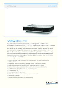
Typical application is to bridge islands of IP-based networks through satellite / wireless / cable modems: o Two-way IP communications o UDP video streaming o IP datacasting Video streaming source
Video streaming client
LAN UDP
LAN UDP
IP Router Gateway
Modulator
IP Router Gateway cable/ wireless/ satellite link
Demodulator
130020
Example: one-way video streaming over UDP
MSS • 845 Quince Orchard Boulevard Ste N • Gaithersburg, Maryland 20878-1676 • U.S.A. Telephone: (240) 631-1111 Facsimile: (240) 631-1676 www.ComBlock.com © MSS 2016 Issued 7/27/2016
Inputs/Outputs GbE LAN
GbE IP Gateway Router
clock-synchronous 1bit serial or 8-bit parallel link
COM-5404
GbE LAN
GbE IP Gateway Router COM-5404
GbE LAN
GbE IP Gateway Router COM-5404
Interfaces GbE IP Gateway Router
Input Signals WAN_RX_DATA _IN[7:0]
GbE LAN
COM-5404
FPGA Developmt platform
WAN_RX_DATA_ VALID_IN
COM-1500
Error Correction Codec COM-1509 COM-7002
WAN_RX_CTS _OUT
PSK APSK QAM Modem COM-1202
WAN_RX_CLK_IN
analog baseband I/Q
GbE LAN
GbE IP Gateway Router COM-5404
Error Correction Encoder COM-1509 COM-7002
Modulator
PSK,APSK,QAM FSK,MSK,GFSK DSSS COM-1402 COM-1028 COM-1519
D/A converters COM-2001 COM-3504
RF modulator
RFout
Definition Input data from the WAN. The data width can be 1-bit or 8-bit depending on the user-selected firmware option. Signals are pulled-down. LVTTL 0 – 3.3V Input data enable. Read the input data at the rising edge of CLK_IN when VALID = ‘1’. Signal is pulled-down. LVTTL 0 – 3.3V Input flow control signal (output). ‘1’ indicates that the COM-5404 is ready to accept DATA_IN input samples into its input elastic buffer. LVTTL 0 – 3.3V. Signal is pulleddown. Input reference clock for synchronous I/O. DATA_IN and VALID_IN are read at the rising edge of CLK_IN. Maximum frequency: 125 MHz. LVTTL 0 – 3.3V
COM-4xxx
Output Signals RFin
RF receiver
COM-3xxx
Demodulator PSK,APSK,QAM FSK,MSK,GFSK DSSS
COM-1202 COM-1027 COM-1518
Error Correction Decoder COM-1509 COM-7002
GbE IP Gateway Router
GbE LAN
COM-5404
130033
For the latest data sheet, please refer to the ComBlock web site: comblock.com/download/com5404.pdf. These specifications are subject to change without notice.
For an up-to-date list of ComBlock modules, please refer to http://www.comblock.com/product_list.html .
Definition Output data to the WAN. The data width can be 1-bit or 8-bit depending on the user-selected firmware option. LVTTL 0 – 3.3V WAN_TX_DATA_ Output data enable. VALID_OUT The receiving end should read data at the rising edge of CLK_OUT when VALID = ‘1’. LVTTL 0 – 3.3V WAN_TX_CTS Input flow control signal (output). _IN LVTTL 0 – 3.3V. Signal is pulled-up WAN_TX_CLK_OUT LVTTL 0 – 3.3V 125 MHz output reference clock. (from internal oscillator). Other Definition Interfaces LAN 10/100/1000 Mbits/s Ethernet LAN. RJ45 connector Supports auto MDIX to alleviate the need for crossover cable. USB USB 2.0 Use USB 2.0 approved cable for connection to a host computer. Maximum recommended cable length is 3’. The USB connection is needed only for a one-time initial IP configuration. Power 4.75 – 5.25VDC. Terminal block. Power Interface consumption is typically 450mA. WAN_TX_DATA _OUT[7:0]
2
Initial Configuration Before the first use, the router must be assigned a static IP address over LAN, USB or through adjacent ComBlocks by following the one-time procedure below: Step 1a (LAN): The COM-5404 is shipped with a static IP address: 172.16.1.128. The easiest way to perform the first configuration is to configure a PC with an address on the 172.16.1.x subnet, or Step 1b (USB): Connect a short USB cable between the COM-5404 and a PC. When using ComBlocks for the first time, the PC will ask for a USB driver. Just follow the instructions and point to the driver located in the ComBlock CD-ROM folder entitled “\Windows Drivers\USB 2.0\Windows Driver”. Point to the proper folder for Windows 7 and below, or Windows 8 and above. Step 2: a) Start the ComBlock Control Center, click on the Communication parameters setup button and select USB as the primary communication channel.
Configuration An entire ComBlock assembly comprising several ComBlock modules can be monitored and controlled centrally over a single connection with a host computer. Connection types include built-in types: TCP-IP/LAN, USB or connections via adjacent ComBlocks. The module configuration is stored in non-volatile memory.
Configuration (Basic) The easiest way to configure the COM-5404 is to use the ComBlock Control Center software supplied with the module on CD. Start the ComBlock Control Center, click on the Communication parameters setup button and select LAN/IP as the primary communication channel. Enter the COM-5404 IP address as previously defined.
b) In the ComBlock Control Center window detect the ComBlock module(s) by clicking the Detect button, next click to highlight the COM-5404 module, then click the Settings button. Step 3: c) Enter a static IP address in the LAN section. The IP address must be unique and must be consistent with your LAN (i.e. the first two or three numbers of the router IP address match the first two or three numbers of your computer’s IP address). This procedure is a one-time procedure required before the first use. Once the router IP address is saved in non-volatile memory, the ComBlock Control Center can communicate with the COM5404 over the LAN.
3
4
Then detect the ComBlock module(s) by clicking the Detect button, next click to highlight the COM-5404 module to be configured, next click the Settings button to display the Settings window shown below:
5
Configuration (Advanced) Alternatively, users can access the full set of configuration features by specifying 8-bit control registers as listed below. These control registers can be set manually through the ComBlock Control Center or by software using the ComBlock API (see www.comblock.com/download/M&C_reference.pdf)
It is either a user-defined field or, when the DHCP client is enabled, assigned automatically. Default gateway
It is either a user-defined static address or, when the DHCP client is enabled, assigned automatically.
All control registers are read/write. Definitions for the Control registers and Status registers are provided below.
Control Registers The module configuration parameters are stored in volatile (SRT command) or non-volatile memory (GUI or SRG command). Parameters LAN
Configuration
Obtain an IP address automatically (DHCP client enabled within)
'1' when this device IP configuration (IP address, subnet mask, default gateway) is obtained automatically from an external DHCP server. '0' when these parameters are static and user-defined below. REG20(1) This router's own IP address. It is either a user-defined static address or, when the DHCP client is enabled, a requested IP address. In the latter case, a DHCP server will automatically assign the IP address which may or may not be the same as the requested address. Check status registers SREG16-19 for the actual IP address.
This router requested IP address
Other local IP nodes must be told of this router IP address (usually referred to as “Default gateway” in the Internet Protocol properties control panel). Format example : 0x AC 10 01 80 designates address 172.16.1.128 Subnet mask
REG0 (MSB) – REG3 (LSB) 4-byte subnet mask has two purposes: (a) Helps the COM-5404 IP router distinguish between local IP destinations within this subnet and remote destinations. Example : 0x FF FF FF 00 designates IP subnet mask 255.255.255.0.
REG4 (MSB) – REG7 (LSB) The router will forward IP frames from the WAN to this gateway when the destination IP address is not local.
IP multicast enable
REG8 (MSB) - REG11(LSB) IP multicast addresses are intended to reach an arbitrary subset of the hosts on a local network. Destination addresses are in the range 224.0.0.0 to 239.255.255.255. 0 = disable forwarding of IP multicast IP frames 1 = enable forwarding of IP multicast IP frames
Directed IP broadcast enable
REG12(5) Directed broadcast IP frames are those packets with IP destination address in the form (Network prefix, 255). For example 172.16.255.255 or 172.16.1.255. IP directed broadcast frames should generally be dropped for security reasons (for example to reduce the risk of DoS attacks). 0 = disable forwarding of directed broadcast IP frames 1 = enable forwarding of directed broadcast IP frames
IP broadcast forwarding enable
REG12(6) IP broadcast frames (those with destination IP address 255.255.255.255) should generally not be forwarded unless specifically authorized below: 0 = disable forwarding of broadcast IP frames 1 = enable forwarding of broadcast IP frames REG12(7)
(b) inform DHCP clients about the subnet size. 6
QoS bandwidth management LAN -> WAN IP forwarding EF PHB Differentiated Services configuration: bandwidth quota Percentage of the overall LAN-to(%) WAN transmit bandwidth allocated to the Expedited Forwarding (EF). Expressed as percentage: 128 represents 100%. REG14 AF1 PHB Differentiated Services configuration: bandwidth quota Percentage of the overall LAN-to(%) WAN transmit bandwidth allocated to the Assured Forwarding class 1 (AF1). Expressed as percentage: 128 represents 100%. REG15 AF2 PHB Differentiated Services configuration: bandwidth quota Percentage of the overall LAN-to(%) WAN transmit bandwidth allocated to the Assured Forwarding class 2 (AF2). Expressed as percentage: 128 represents 100%. REG16 AF3 PHB Differentiated Services configuration: bandwidth quota Percentage of the overall LAN-to(%) WAN transmit bandwidth allocated to the Assured Forwarding class 3 (AF3). Expressed as percentage: 128 represents 100%. REG17 AF4 PHB Differentiated Services configuration: bandwidth quota Percentage of the overall LAN-to(%) WAN transmit bandwidth allocated to the Assured Forwarding class 4 (AF4). Expressed as percentage: 128 represents 100%. REG18 WAN configuration Scrambling Enable (1) or disable (0) the V.35 enable scrambler used on the 1-bit serial link when forwarding IP frames to the WAN. This self-synchronizing scrambling’s objective is to randomize the bit stream and avoid the short repetitive and unbalanced pattern of 0x7E empty frames inherent with the use of HDLC framing. Enable to prevent confusion at Viterbi FEC decoders and demodulators bit timing loops. Descrambling enable
DHCP server configuration DHCP server Enable (1) or disable (0) the built-in enable DHCP server. Note: this DHCP server requires a static IP address (i.e. the DHCP client must be disabled) REG20(0) IP pool size Maximum number of consecutive IPv4 addresses that the DHCP server is allowed to assign to DHCP clients. IP pool starting address
Lease time
DNS address
Default gateway
REG21 The DHCP server will assign DHCP clients IPv4 addresses from a range starting at this base address. This base address is only identified by its LSB. The most significant address bytes are those of this device. REG25: LSB IP address lease time to DHCP clients, in seconds. Typically 86400 s (1 day) REG26 (LSB) – REG29 (MSB) The DHCP server tells clients about one possible DNS to use. For example 08.08.08.08 for Google DNS. REG30 (MSB) – REG33 (LSB) The DHCP server tells clients about the default gateway. Typically points to this device to use the WAN but could point to another gateway. REG34 (MSB) – REG37 (LSB)
Most changes are enacted immediately upon (re-)writing to the last control register REG44, without a need to reset the module.
REG12(0) Enable (1) or disable (0) the V.35 descrambler used on the 1-bit serial link, when receiving IP frames from the WAN. REG13(0)
7
over when reaching 0xFFFFFFFF.
Options Some configuration parameters are not selectable dynamically at run-time, but selected by enabling one of several FPGA firmware options. All firmware options are freely downloadable from www.comblock.com/download.
Number of received bytes (WAN to LAN)
Changing the functionality may require loading the firmware once using the ComBlock control center ( button) if it is not already loaded. Then switching between the stored firmware options The selected firmware option is automatically reloaded at power up or upon software command within 1.2 seconds Option
Definition
-A
1-bit serial WAN interface
-B
1-bit serial WAN interface, flipped tx/rx I/O pins (for back to back connection)
-C
8-bit parallel WAN interface
-D
8-bit parallel WAN interface, flipped tx/rx I/O pins (for back to back connection)
SREG32 (LSB) – SREG35 (MSB) Erroneous IP frames
WAN transmit bit rate DHCP server monitoring
Status Registers
MAC address IP address
Subnet mask
Default gateway IP address Number of transmitted bytes (LAN to WAN)
Monitoring At power-up, the hardware platform performs a quick self check. The result is stored in status registers SREG0-9 Properly operating hardware will result in the following sequence being displayed: SREG0-9 = 2C F1 95 xx 0F 01 00 00 24 22 Unique 48-bit hardware address (802.3). SREG10 (MSB) – SREG15 (LSB) Actual IPv4 address (whether static IP or automatically assigned) SREG16(MSB) - SREG19(LSB) Actual subnet mask (whether static or automatically assigned) SREG20(MSB) - SREG23(LSB) Actual default gateway IP address (whether static IP or automatically assigned) SREG24(MSB) - SREG27(LSB) Cumulative number of IP frames bytes sent in the LAN to WAN direction. Excludes HDLC framing overhead and empty HDLC frames. 32-bit byte count. Counter rolls
A measure of the link quality is the number of IP frames lost during transmission. Cumulative number of IP frames received on the WAN side with bad CRC and subsequently dropped.
32-bit byte count. Counter rolls over when reaching 0xFFFFFFFF.
Monitoring Parameters Hardware self-check
SREG28 (LSB) – SREG31 (MSB) Cumulative number of IP frames bytes received in the WAN to LAN direction. Excludes HDLC framing overhead and empty HDLC frames. 32-bit byte count. Counter rolls over when reaching 0xFFFFFFFF.
Gateway presence detected
SREG36 (LSB) – SREG39 (MSB) WAN transmit bit rate expressed as number of bytes in a 100ms window. SREG40 (LSB) – SREG43(2:0) (MSB) Monitoring key DHCP server counters: SREG44: received DHCPDISCOVER SREG45: received DHCPREQUEST addressed to this server (continuation of the DHCPDISCOVER) SREG46: received DHCPREQUEST (renewing state) SREG47: received DHCPREQUEST (init reboot state) SREG48: sent DHCPACK messages, concluding successful dynamic IP address assignments. The counters above are modulo 256. 1 = gateway responded to ARP requests 0 = no response from specified gateway SREG49(0)
As the monitoring data is constantly changing, it is important to be able to prevent changes while reading a multi-byte parameter. The monitoring data is latched upon reading register 8. Therefore, status register 8 should always be read first.
8
Digital Test Points These test points on the J9 connector (top side) are designed for real-time monitoring using an oscilloscope probe. The main focus of these test points is to help monitor proper data flow. Test Definition Point LAN to WAN direction J9.A29 Incoming Ethernet LAN data packet (not necessarily an IP frame) Timescale: 8 ns per byte. J9.A30 IP forwarding pulse. High at the end of the frame when all IP forwarding criteria are met: IP frame, remote IP destination, no congestion in the class queue, etc. J9.A31 Forwarding IP frame to WAN. Frame is HDLC encoded. Timescale: 8 ns per bit or byte (depending on WAN interface data width) J9.A32 IP forwarding Differentiated Services congestion: at least one queue is full. WAN to LAN direction J9.A33 Receiving HDLC encoded IP frame from WAN. J9.A34 0x7E flag marking the start and end of HDLC encoded frames. J9.A35 Bad CRC16 in HDLC frame received from the WAN. The frame is discarded. J9.A36 No routing information available in the routing table, no ARP reply from the target. The packet is discarded. J9.A37 Receiver buffer overflow condition. The packet is discarded. J9.A38 IP router sending IP frame to Ethernet LAN. Timescale: 8ns per byte. DONE
1 when the FPGA is loaded with a valid .bit configuration file. The COM-5404 is operational typically 1.2 seconds after power up.
Principle of operation Concept The COM-5404 forwards IP frames from a RJ-45 10/100/1000 Mbps LAN interface to a clocksynchronous modem interface and vice versa. The interface can be 1-bit serial or 8-bit parallel. The IP frames received over the LAN are stripped of their link layer information: Ethernet source address, destination address and type are removed, keeping only the IP fields. TCP, UDP, ICMP and IGMP packets are processed since they are transmitted as IP frames. Non IP frames are rejected. IP frames whose Time-To-Live field has reached zero are discarded. For the other packets, the TTL is decremented. The COM-5404 implements Differentiated Services (DiffServ) whereby IP forwarding from LAN to WAN is prioritized on the basis of the IP frame DSCP field. Five queues handle different traffic classes, including Expedited Forwarding (EF) for low-loss, low-latency, low-jitter frames and four Assured Forwarding (AF1-AF4) classes. Frames are discarded without notification if the associated queue is full. The IP frame maximum size (maximum transmission unit (MTU)) is 1500 bytes. No datagram fragmentation is necessary nor used. The IP frames are then encapsulated within a bitserial or byte-wise HDLC frame, one packet per frame. A 16-bit CRC is inserted at the end of each frame to detect errors upon reception. HDLC encoding transmits empty frames when no payload data is available. Bit-serial HDLC frames can be subsequently scrambled with a V.35 scrambler to ensure balance between 0's and 1's and guarantee bit transitions (for a well behaved modulated spectrum and to assist demodulator acquisition when applicable). The resulting stream is then sent to the WAN over a continuous link, typically using a modem. 9
The reverse process is performed at the receiving end. Erroneous packets which do not pass the CRC test are rejected.
Four other queues are associated with “Assured Forwarding” per-hop behavior (see RFC-2597)
IP forwarding (LAN-TO-WAN)
Users can select the link bandwidth apportionment among the five queues through the graphical user interface.
The forwarding rules are specified in the RFC1812 document “Requirements for IP Version 4 Routers”.
IP routing (WAN-TO-LAN)
The decision to forward a LAN IP frame to the remote WAN is based solely on the destination IP address. To determine whether a frame is destined to a local (LAN) or remote (WAN) IP address, the router compares the masked destination address (Destination IP address & subnet mask) with the masked router address (IP router own IP address & subnet mask). When this comparison is false, the IP frame is forwarded to the WAN. Example: Router IP address: 192.68.0.2 Router subnet mask: 255.255.255.0 Frame destination IP address is 74.54.97.66 Masked frame destination: 74.54.97.0 Masked router address: 192.68.0.0 Since the masked destination does not match the masked router address, the frame is not for a local destination. Consequently the router will forward the frame to the WAN. IP broadcast frames (those with destination IP address 255.255.255.255) are not forwarded unless specifically authorized. IP unicast frames
Differentiated services The router also prioritizes IP forwarding based on the IP header differentiated services code point (DSCP). A forwarded IP frame is sent to one of five queues depending on its DSCP: One queue is reserved for low-loss, low-latency, low-jitter, and assured bandwidth service. It is associated with “Expedited Forwarding” (EF) perhop behavior. The recommended DSCP value for EF is `101110' (see RFC-2474)
The stream received over the link undergoes V.35 descrambling and HDLC decoding to reconstruct IP frames. Erroneous frames which do not pass the CRC test are rejected. Valid IP frames are re-encapsulated inside an Ethernet packet, one IP frame per Ethernet packet. The IP address – MAC address relationships are stored within a routing table to expedite the Ethernet packet construction. The routing table includes up to 512 local IP addresses, with associated 48-bit MAC address and 'freshness' stamp. When the routing table has no information regarding the destination IP address, it will attempt to find out by means of an Address Resolution Protocol (ARP) query-reply transaction. The router will broadcast an ARP request asking “whois the destination IP address?” and will wait for the ARP reply with the MAC information.
Co-located DHCP server A built-in DHCP server automatically assigns IP addresses to local IP clients, for ease of network management. The addresses are taken from a pool of contiguous IP addresses and leased for a limited time. In addition to assigning IP addresses, the DHCP server informs clients about important network management parameters such as gateway and DNS.
Co-located DHCP client When enabled, the built-in DHCP client automatically fetches an IP address for this device. In most use cases, use of the DHCP client is mutually exclusive with use of the DHCP server.
10
MAC INTERFACE
DHCP SERVER ARP REPLY
MAC Receive Interface
PACKET PARSING
REMOTE MONITORING & CONTROL INTERFACE
PING REPLY
ROUTING TABLE
UDP_TX
ARP REQUEST
TCP_RXBUF
UDP_RX TCP_TXBUF TCP SERVER
TCP_TX
IP FORWARDING DIFFSERV QUEUING
IP ROUTING
MAC Transmit Interface
Arbitration
HDLC ENCODING
HDLC DECODING
V.35 SCRAMBLING
V.35 SCRAMBLING
WAN / MODEM INTERFACE 140005
11
Network Administration GbE LAN
Simple network administration
DHCP server assigned dynamic IP addresses
GbE LAN synchronous serial link (cable, satellite, etc)
172.16.1.10 static IP 172.16.1.1 172.16.1.11
172.16.1.12
COM-5404 Gateway1 DHCP server enabled Base IP address: 172.16.1.10
COM-5404 Gateway2
192.68.0.20
192.68.0.21
DHCP server enabled Base IP address: 192.68.0.20
172.16.1.13 Network devices configured as "DHCP enabled" (dynamic IP addresses are assigned automatically by a DHCP server)
static IP 192.68.0.2
192.68.0.22
192.68.0.23
Gateway3
static IP 192.68.0.1 192.68.0.24
GbE LAN
Network devices configured as "DHCP enabled" (dynamic IP addresses are assigned automatically by a DHCP server)
Internet
The diagram above illustrates a simple network administration scheme, whereby only gateways are administered with fixed (static) IP addresses. The other network devices automatically fetch their network configuration (IP address, subnet mask, DNS) from a DHCP server, like the one in the COM-5404. For example, a PC running Microsoft’s Windows operating system would be configured as per the right panel:
LVTTL I/O Format 12
The user can select among several formats (8-bit parallel mode or 1-bit serial) for the input and output connectors through control registers.
LAN Network
Serial HDLC A bit-serial HDLC format can be used to convey data over a synchronous bit-serial link such as a wireless or satellite link. The HDLC objective is three-fold: (a) Tell the receiver side when no information is available for transmission (sending empty frames).
10/100/1000 Mbps Ethernet LAN RJ-45
(b) Implement multiple virtual channels over a common physical link (unused feature here) to WAN 1 or 8-bit synchronous LVTTL
IP forwarding
IP routing
from WAN 1 or 8-bit synchronous LVTTL 8
8 byte HDLC encoding
8
1
(c) Recover the original bit-to-byte alignment of the original byte data stream.
byte HDLC encoding
bit-serial HDLC encoding
bit-serial HDLC encoding
Serial HDLC format
8
This section provides details as to the serial HDLC format used on the synchronous serial link. It is intended for developers and can be skipped by most users.
1
140010
I/O Format Timing for the LVTTL interface is shown below: Input Input data is read at the rising edge of CLK_IN
CLK_IN
7E Address Field 1 byte 1 byte opening flag
Information Field variable-length
FCS 2 bytes CRC16
7E 1 byte closing flag
Data is encapsulated within variable length frames starting and ending with a 0x7E flag. A two-byte CRC check can be used to verify if the frame is error free. A frame encapsulates a single IP frame. The information field always contains an integer number of bytes. The most significant bit is transmitted first.
SAMPLE_CLK_IN DATA_IN Best time to generate data at the source is at the falling edge of CLK_IN
Output Output data is generated at the falling edge of CLK_OUT
The maximal frame length (before accounting for bit stuffing) is 1500 bytes of information (IP MTU) plus 5 bytes of overhead. The following bit-stuffing mechanism is used on the transmit side for all fields except the opening and closing flags: a ‘0’ is inserted after five consecutive 1’s. The address field is used to indicate the type of data conveyed within. The current implementation uses only a single virtual channel 01.
CLK_OUT SAMPLE_CLK_OUT DATA_OUT
Byte HDLC format Best time to read data is at the rising edge of CLK_OUT
This section provides details of the byte HDLC encapsulation method used on the synchronous 813
bit parallel data link. It is intended for developers and can be skipped by most users. TBD
Recovery The COM-5404 is protected against corruption by an invalid FPGA configuration file or an invalid user configuration. To recover from such occurrence, connect a jumper in JP1 position 2-3 prior and during power-up. This prevents the FPGA configuration. Keep the jumper at least 2 seconds after power up, then remove it. Keep the power on. This will restore USB communications with the ComBlock Control Center through the J2 DEV USB port. Once this is done, the user can safely restore the user configuration and/or re-load a valid FPGA configuration file into flash memory using the ComBlock Control Center GUI.
LEDs 2 LEDs within the LAN RJ-45 jack provide summary information as to the LAN: Link, activity and negotiated speed. Link/Activity Link off 1000 Link / no activity 1000 Link / activity 100 Link / no activity 100 Link / activity 10 Link / no activity 10.Link / activity
LED2 (left) Green Off On Blinking Off Off On Blinking
LED1 (right) Yellow Off Off Off On Blinking On Blinking
Schematics The board schematics are available on-line at
TCP-IP for remote M&C
http://comblock.com/download/com_1500schematics.pdf
Remote monitoring and control of this device is possible through a TCP connection to port 1028. The device acts as a TCP server, listening for a connection from a remote client such as the ComBlock Control Center software.
http://comblock.com/download/com_5102schematics.pdf
for the main board and for the Ethernet LAN adapter.
Pinout
Ping
USB Connectors
The module responds to ping requests with size up to 470 bytes. Ping can be used to check the module response over the LAN network. Ping can be used at any time, concurrently with other transmit and receive transactions. For example, on a Windows operating system, open the Command prompt window and type “ping –t –l 470 172.16.1.128” to send pings forever of length 470 bytes to address 172.16.1.128.
Both USB ports are equipped with mini type AB connectors. (G = GND). In both cases, the COM-1524 acts as a USB device.
G
5
ID
4
D+
3
D-
2
1
5V
Power Up The LAN link is available 2.05 seconds after power up.
14
LAN Connector RJ1 The RJ-45 Jack is shielded with top and side ground taps. It supports MDIX and can therefore be connected directly to a PC or a LAN switch using Cat 5 cable. There is no need for crossover cable.
Mechanical Interface Mounting hole (-0.350", 2.840") Overhang 0.100"
Mounting hole (2.840", 2.840")
Mounting hole (0.160", 2.840")
Corner (3.000",3.000")
USB DEV port. USB HI-SPEED POWER MiniAB Overhang port. MiniAB (+5VDC) 0.075" TERMINAL BLOCK J2
J1
J3 RJ45 LAN
RJ1 A1 pin center (x, 2.485")
ARM TEST PTS
J1
POWER (+5VDC) TERMINAL BLOCK
FPGA JTAG Digital interface 98-pin card-edge (PCIe type)
Digital interface 98-pin card-edge (PCIe type)
COM-1500
COM-5102 J6
J9 TOP VIEW Connector P/N Sullins NWE49DHRN-T941
HDMI IN
J7 card-edge EXT REF to ARM JTAG
HDMI OUT
Mounting hole (2.840", 0.160") Corner(-1.465", 0.000")
Mounting hole (-0.350", 0.160")
Mounting hole (0.160", 0.160") Corner(0.000", 0.000")
Mounting holes diameter: 0.125" Use 5/8" spacers between two stacked boards Board thickness 0.062" 130038
15
Right Connector J9 Top WAN_TX_CLK_OUT WAN_TX_DATA1B_OUT
Bottom
A1 B1
WAN_TX_DATA_VALID_OUT
Top WAN_RX_CLK_IN WAN_RX_DATA1B_IN
GND WAN_TX_CTS_IN
WAN_RX_CLK_IN
WAN_RX_DATA_VALID_IN
GND WAN_RX_CTS_OUT
WAN_RX_DATA_VALID_IN
WAN_TX_CLK_OUT
WAN_RX_DATA1B_IN
WAN_TX_DATA1B_OUT
WAN_RX_CTS_OUT
WAN_TX_CTS_IN
GND
TEST POINTS A29 A30 A31 A32 A33 A34 A35 A36 A37 A38
Bottom
A1 B1
GND
GND
M&C_TX M&C_RX A49 B49 130032
Configured as 1-bit synchronous serial interface firmware option -A
WAN_TX_DATA_VALID_OUT
GND
TEST POINTS A29 A30 A31 A32 A33 A34 A35 A36 A37 A38
GND
GND
M&C_TX M&C_RX A49 B49 130034
Configured as 1-bit synchronous serial interface, flipped tx/rx firmware option –B 16
Top WAN_TX_CLK_OUT WAN_TX_DATA_OUT(0) WAN_TX_DATA_OUT(2) WAN_TX_DATA_OUT(4) WAN_TX_DATA_OUT(6) WAN_TX_DATA_OUT(7) WAN_TX_CTS_IN
WAN_RX_CLK_IN WAN_RX_DATA_IN(0) WAN_RX_DATA_IN(2) WAN_RX_DATA_IN(4) WAN_RX_DATA_IN(6)
Bottom
Top
A1 B1
WAN_TX_DATA_VALID_OUT WAN_TX_DATA_OUT(1) WAN_TX_DATA_OUT(3) WAN_TX_DATA_OUT(5) GND
WAN_RX_DATA_VALID_IN WAN_RX_DATA_IN(1) WAN_RX_DATA_IN(3) WAN_RX_DATA_IN(5) WAN_RX_DATA_IN(7)
WAN_RX_CTS_OUT
Bottom
A1 B1
WAN_RX_CLK_IN WAN_RX_DATA_IN(0) WAN_RX_DATA_IN(2) WAN_RX_DATA_IN(4) WAN_RX_DATA_IN(6) WAN_RX_DATA_IN(7) WAN_RX_CTS_OUT
WAN_RX_DATA_VALID_IN WAN_RX_DATA_IN(1) WAN_RX_DATA_IN(3) WAN_RX_DATA_IN(5) GND
WAN_TX_CLK_OUT
WAN_TX_DATA_VALID_OUT
WAN_TX_DATA_OUT(0) WAN_TX_DATA_OUT(2) WAN_TX_DATA_OUT(4) WAN_TX_DATA_OUT(6)
WAN_TX_DATA_OUT(1) WAN_TX_DATA_OUT(3) WAN_TX_DATA_OUT(5) WAN_TX_DATA_OUT(7)
WAN_TX_CTS_IN
GND
TEST POINTS A29 A30 A31 A32 A33 A34 A35 A36 A37 A38
GND
GND
TEST POINTS A29 A30 A31 A32 A33 A34 A35 A36 A37 A38
GND
GND
M&C_TX M&C_RX A49 B49 130036
Configured as 8-bit parallel synchronous interface firmware option -C
GND
M&C_TX
M&C_RX A49 B49 130037
Configured as 8-bit parallel synchronous interface, flipped tx/rx firmware option option -D 17
I/O Compatibility List (not an exhaustive list) COM-1500 FPGA + ARM development platforms COM-1509 Error Correction Codec 120Mbits/s COM-7002 TPC Error Correction Codec
Configuration Management This specification is to be used in conjunction with VHDL software revision 1 and ComBlock Control Center revision 3.07 and above.
Acronyms DNS IP LAN LSB MSB WAN
Domain Name Server Internet protocol Local Area Network Least Significant Byte Most Significant Byte Wide Area Network
ComBlock Ordering Information COM-5404 GbE IP Gateway Router ECCN 5A991.b.4.a MSS • 845-N Quince Orchard Boulevard• Gaithersburg, Maryland 20878-1676 • U.S.A. Telephone: (240) 631-1111 Facsimile: (240) 631-1676 E-mail:
[email protected]
18