Gas Exchange and Exhaust Condition Modeling of a Diesel Engine using the Engine Dynamics Library
Johan Dahl † Daniel Andersson ‡ †Volvo Group Truck Technology, Control Systems, Gothenburg, Sweden ‡Modelon AB, Lund, Sweden
Abstract
this paper the newly developed Engine Dynamics In Library is presented. Ever increasing consumer and regulatory demand for improved fuel economy and lower emissions forces the engines and Engine After Treatment Systems (EATS) to be improved continu ously. Since the complete system is very complex, models are useful in cost effectively developing new control strategies and select hardware. The library is based on a mean-value combustion model and the focus lies on modeling the gas exchange with real-time like simulation times, useful for engine optimization and for evaluation of control strategies. The library contains models of the standard engine components such as manifolds, pipe, turbines, compressors, valves, mechanics, etc. Simulation results from Dymola for a 13 L Volvo truck engine demonstrate that the model captures the transient flow and temperatures and emission trends, and has sufficient accuracy to be useful in engine optimization. The physical modeling approach allows for virtual prototyping by replacing individual components, which is an important advantage over black-box modeling. It is shown that the model captures essential system properties in the gas exchange, such as non-minimum phase behavior and sign reversal for VGT and EGR valve actuation. The model has been calibrated using surface fitting of maps and leastsquares estimation of parameters in Matlab, as well as parameter optimization using JModelica and FMI. Keywords: Engine modeling; Engine simulation; Air Gas management
1
Introduction
As the requirements on the engine and EATS become more strict, a new development process of control strategies and hardware concept selection is needed as only using engine test cells and vehicles in the development process is too time consuming and expensive. DOI 10.3384/ecp12076101
In the new development process at Volvo, SoftwareIn-the-Loop (SIL) simulations are used more extensively in the control strategy and hardware development. With the introduction of US10 and soon EU6 legislation ultra low on-road emissions are required. Future emission legislation will also include CO2 , N2 O and NO2 [1]. To fulfill these requirements with opti mal fuel consumption, the significant interaction between the engine and EATS must be considered and control strategies for both components need to be optimized together [2]. This requires good engine models with accurate modeling of the engine out conditions. In particular, focus has been on predicting the sensitivity of the dynamic response and engine exhaust temperature with respect to the air gas management. Issues about control system design or strategy are not in the scope of this paper. Nevertheless, a good physical model of the engine provides useful insights for both the control system designers and hardware selection. The engine model is also useful for finding suitable requirements of the EATS system. For example the emission transient response can be a limiting requirement for the needed volumes of the Diesel Oxidation Catalyst (DOC), Diesel Particulate Filter (DPF) and Selective Reduction Catalyst (SCR) in order to fulfill the EU6 emission legislation. In this paper the Engine Dynamics Library (EDL) is presented. The library is implemented in Modelica and consists of mean-value models of standard engine components. The focus of the model has been on capturing the transient engine response and the engine outlet conditions as these features are important for the total engine and EATS optimization. Comparison results between test cell measurements and simulation results of a 13 liter Volvo truck engine certified for the Post New Long-Term (PNLT) emission legislation, introduced in 2009, are presented. The Engine Dynamics Library is a new commercial library offered by Modelon.
Proceedings of the 9th International Modelica Conference September 3-5, 2012, Munich, Germany
101
Gas Exchange and Exhaust Condition Modeling of a Diesel Engine using the Engine Dynamics …
2
Engine modeling in Dymola
which contains examples of configured engine models and experiments. EDL is not based on the Modelica.Media or Modelica.Fluid packages. Medium property models and base classes for fluid systems modeling are based on classes in the Modelon Base Library, which is delivered with EDL. EDL share base classes with Modelon’s Liquid Cooling Library (LCL), Heat Exchanger Library (HXL) and Vehicle Dynamics Library (VDL), making them all compatible. The libraries can be used together for different kinds of vehicle analysis, for example EDL, LCL and HXL together forms a powerful solution for thermal management analysis, and EDL and VDL can be used together for drivability analysis.
Today several tools exist in which physical or semiphysical models can be implemented. Dymola [3], which is based on the open standard Modelica language, was chosen as the tool for developing an engine model library. The main reasons for choosing Modelica are the flexibility, expressiveness and openness of the language, as compared to domain specific tools, and the possibility to extend tools and libraries with in-house IP and know-how. Others have demonstrated that Modelica is suitable for engine modeling [4, 5], but the focus has not been on gas exchange modeling or predicting the exhaust gas temperature entering the EATS. The following sections describe EDL and the compo2.2 Cylinder nent and medium models that have been implemented. The cylinder component (Fig. 2) is based on a mean value combustion model as 2.1 Library structure described in [6]. The component boundary conditions are boost pressure and Figure 2: temperature, exhaust manifold pressure, Cylinder engine speed, fuel injection and other control signals. The empirical correlations described in the following sections (often 2-dimensional maps) can easily be replaced by any equation based models, for example simple qualitative models found in literature, regression models or neural network models. Flow model The cylinder mass flow is modelled by means of a volumetric efficiency defined as: m˙ charge = ρin · λ (pBoost , ωe ) ·
Vd ωe · N 2π
(1)
where λ is the volumetric efficiency, Vd is the displaced volume, N is the number of revolutions per cycle, pBoost is the inlet manifold pressure and ωe is the engine rotational speed. λ (pBoost , ωe ) is modelled by a two-dimensional map obtained from measurements. Torque model Figure 1: EDL and sub packages (left), Engines pack- For the torque model we define brake mean effective pressure, pme and fuel mean effective pressure, pmϕ , age (right) as: The structure of EDL is shown to the left in Fig. 1. Hl · mϕ Te · 4π pme = pmϕ = (2) The library is divided into packages for each physiVd Vd cal component, plus some additional packages for supporting components and classes. There is also a packwhere Te is the engine torque, Hl is the fuel lower age named Engines, shown to the right of Fig. 1, heating value and mϕ is the mass of fuel burnt per 102
Proceedings of the 9th International Modelica Conference September 3-5, 2012, Munich Germany
DOI 10.3384/ecp12076101
Session 1C: Power and Energy
combustion cycle. The engine efficiency can then be 2.3 written as: ηe = pme /pmϕ (3)
Compressor and turbine
Following the Willans Approximation [6], a torque model on the following form is implemented: pme = e(pmϕ , ωe ) · pmϕ − pme0 f (ωe ) − pme0g
(4)
where the energy conversion efficiency, e is modelled by a two-dimensional map obtained from measurements, the mechanical friction, pme0 f , is mapped from engine speed, pme0g , is the cycleaveraged pressure difference between inlet and exhaust manifolds.
Figure 3: Compressor and VGT
The compressor and variable geometry turbine (VGT) components (Fig. 3) are both parameterized by maps for mass flow rate and isentropic efficiency. The components model a polytropic thermodynamic process with mechanical power crossing the component boundary via a rotational mechanical flange. Quasistatic balance equations for conservation of substance Exhaust gas properties mass and energy are used, i.e. storage of mass and The outlet exhaust gas temperature is mapped from energy is not considered and the outlet properties reengine speed and injected fuel. The transferred heat spond instantly to property changes of the inlet flow. to the cylinder block is obtained from energy balance These equations assume: over the component boundaries. • The amount of mass inside the component is The composition of species in the exhaust gas is modsmall compared to that in the upstream and downelled by a stoichiometry matrix for the combustion. stream pipes, which is covered by volume comComplete combustion of the injected fuel is assumed. ponents connected to these components. The NOx and soot generation is modelled by a regression model [7] on the form: • The heat capacity of the solid parts are lumped toy(t) = φ T θ + e(t)
(5)
where y = (CNOx ,CSoot )T are the NOx and soot concentrations of the exhaust gas, the regressor φ = (1, u1 , u21 , ..., uN1 , u2 , ...)T contains the first and higher order terms of the following signals: • Injected fuel amount, m f
gether with the wall heat capacities of the volume components connected upstream and downstream of these components. • The rotational kinetic energy of the solid parts is modeled by a separate inertia component connected to the rotational flange connector of these components.
• Fuel injection timing, ζ
The mapped isentropic efficiency, ηis , defines the • Needle opening angle (controls the fuel injection deviation from an isentropic process [8]. pressure), β f hout,isentropic − hin ηis = (Compressor) (6) hout − hin • CO2 concentration in the inlet manifold, CCO2 hout − hin ηis = (Turbine) (7) • Inverse stoichiometric air to fuel ratio, λ −1 hout,isentropic − hin • Engine speed, ωe θ are the model parameters and e is the model error. In the experiment described in section 3.2, all of the input signals to the model come directly from model control signals or boundary conditions, except for the inlet manifold CO2 concentration and air to fuel ratio. These variables are simulated in the engine system model and the simulated values are used as inputs to the emission model. DOI 10.3384/ecp12076101
where hin is the inlet specific enthalpy, hout is the outlet specific enthalpy and hout,isentropic is the outlet specific enthalpy of an isentropic process. The variable geometry turbine is modeled using several maps of isentropic efficiency and mass flow rate for different positions, the properties are interpolated linearly between the mapped geometry settings. The turbine model currently contains no compensation for the upstream pressure oscillations. Internal losses
Proceedings of the 9th International Modelica Conference September 3-5, 2012, Munich, Germany
103
Gas Exchange and Exhaust Condition Modeling of a Diesel Engine using the Engine Dynamics …
from heat transfer to the housing and mechanical friction are currently modeled as a constant efficiency factor. The turbo moment of inertia is captured by a separate inertia component connected between the compressor and turbine components in the engine system model.
for air and exhaust gas are used. Outgoing flows from the volume carry the average medium properties of the total volume.
2.6
Pipes
The pipe models provided in the library consider pressure drop due to friction 2.4 Heat exchangers and optionally also heat transfer effects. Several friction models can be chosen, Figure 6: A quasi-static heat exchanger model with but also here eq. 8 is used. The Air pipe table based efficiency is implemented heat transfer model is interchangeable as model in EDL. It does not contain storage of well, with the options: 1) Constant heat mass or energy and the outlet fluid propFigure 4: transfer coefficient, 2) Dittus-Boelter correlation for erties respond instantly to inlet propHeat forced convection in turbulent flow (Coefficients can erty changes. The component has interexchanger be adjusted by the user). Optionally a dynamic mochangeable friction models with different mentum balance can be used. levels of detail for the primary and secondary flow channels. A model on the following form was chosen because it is easily calibrated to fit mea- 2.7 Valves sured data: ρ d p = f · · vn (8) There are a number of valve models 2 available in EDL. The first one is deHere d p is the pressure drop over the channel, f is the signed to be easily parameterized from friction factor, ρ is the fluid density, v is the flow ve- measured data. It defines a flow equalocity and n is a constant. Note that for n = 2, this tion for the fully opened setting as eq. 8. Figure 7: corresponds to the Darcy-Weisbach equation for pres- The valve characteristics are represented Valve sure loss due to friction in a pipe. The constants f and by means of a relative open area that is model n are chosen to fit measurement data. governed by the actuation signal. LinThe heat transfer is modeled by defining heat ex- ear, quadratic and tabulated characteristics are availchanger efficiency as ε = Q/Qmax . The maximum able. The second one is implemented according to transferable heat Qmax is calculated from the heat ca- the IEC 534/ISA S.75 standards for valve sizing. It pacity flow and inlet temperatures of the two chan- accounts for fluid compressibility effects, as well as nels. The model is parameterized by specifying a two- choked conditions. For the engine model presented in dimensional map for the efficiency from the mass flow this paper, the first model is used because it is easier rates in the two channels. to parameterize from measurements and choked conditions do not occur under normal operation. A butterfly type valve model has been implemented as 2.5 Volumes well, including flap mechanism, torque generation on All fluid mass and energy storage is modthe flap by the gas flow and mechanical friction. elled in volume components by dynamic Figure 5: mass and energy balance equations. An Two port 2.8 Medium models ideal mixture is assumed and a number air volume The medium property models are implemented as reof different components are available, which have different port configurations. The volume placeable packages with high flexibility, similar to that models have the option to consider wall heat capac- of the Modelica.Media package. Ideal gas mixtures ity, heat transfer between fluid and wall (constant heat based on the NASA coefficients [9] can be created and transfer coefficient model) and heat transfer to the sur- used. roundings. There is a special volume model for the in- In addition to this, a simplified medium model aslet manifold that can handle incoming flow in a differ- suming a linear function for specific heat capacity of ent medium model representation by mapping the fluid temperature, Cp (T ), has been implemented for perforspecies between the mass fraction vectors of the two mance reasons. By definition, the specific enthalpy medium models. This is necessary if separate models function, h(T ), will become quadratic in temperature 104
Proceedings of the 9th International Modelica Conference September 3-5, 2012, Munich Germany
DOI 10.3384/ecp12076101
Session 1C: Power and Energy
under this assumption. In static component models, the upstream temperature T (h) is calculated from the specific enthalpy of the inlet fluid connector. An explicit function for this calculation greatly improves simulation performance for system models with several such components, as the non-linear systems of equations can be reduced or completely avoided. The medium models are compatible, so all component models can carry any of the medium model types. Available in EDL are some pre-defined mixtures, used as air or exhaust gas models. The components included are CO2 , H2 O, O2 , N2 and Ar for both NASA and linear Cp (T ) models. Also a single component dry air model is provided. To model emissions, some pre-defined exhaust gas mixtures include trace components for NOx , Soot, HC and CO. The trace components are assumed to be carried by fluid flow but don’t affect the thermodynamic properties of the fluid.
2.9
Mechanical
Basic rotational mechanical components are available in EDL, such as inertia and ideal gear models. The mechanical connectors of the turbo components and cylinder component are compatible with the mechanical components in the Modelica Standard Library.
3
Engine system model
A 13 liter Volvo engine certified for the Post New Long-Term (PNLT) emission legislation has been modeled using EDL. The engine is equipped with variable geometry turbine, exhaust gas recirculation governed by a valve, throttle, EGR cooler, intercooler and unit injectors. The purpose of the simulation model is to perform similar experiments that are performed in engine test cells, where the engine is mounted to an electrical dynamometer which directly controls the engine speed.
3.1
Model description
The engine system model is configured as shown in Fig. 8. The upper left connector is the air inlet connector that should be connected externally to a component defining air temperature and pressure boundary conditions. The components in the air path are connected to represent the engine system design, indicated with light blue in the figure. First there is a pipe component modeling the pressure drop over the air filter (1). Then follows compressor (2), intercooler (3) and throttle (4) DOI 10.3384/ecp12076101
Figure 8: Engine system model with: Air filter (1), Compressor (2), Intercooler (3), Throttle (4), Turbo inertia (5), Inlet manifold (6), Cylinder block (7), Drive shaft (8), Exhaust manifold (9), EGR valve (10), EGR cooler (11), Venturi (12), VGT (13), Muffler (14), Heat transfer (15, and more)
components, each separated by volume components. The compressor is connected to an inertia model (5) that is also connected to the VGT component (13). The throttle in the lower left is connected to the inlet manifold component (6). This is a volume model that also accounts for the thermal mass of the wall and heat transfer between the gas and wall. The inlet manifold has two more connectors for gas (orange). One is connected to the cylinder block and the other is the inlet for EGR gas. The cylinder block (7) has a rotational connector for the drive shaft that is connected to an external connector to the right in the figure (8). It is also possible to enable a support connector for the reactive torque, but it is not used here. There are real input signal connectors for injected fuel, injection timing and needle opening angle. The exhaust gas port is connected to the exhaust manifold (9), which is also a volume model including thermal mass of the wall. There is an outlet port for the exhaust gas recirculation path that is connected directly the the EGR valve (10). This is connected to a volume and then to the EGR cooler (11) and venturi (12). The venturi component is a pure sensor model that does not affect the gas flow rate or properties. The EGR gas path is then fed back to the inlet manifold.
Proceedings of the 9th International Modelica Conference September 3-5, 2012, Munich, Germany
105
Gas Exchange and Exhaust Condition Modeling of a Diesel Engine using the Engine Dynamics …
For each volume model there is a unique pressure and temperature state introduced. As a consequence of the model layout the flow through the EGR valve is calculated from the pressure difference between the exhaust manifold and EGR volume components. The pressures are calculated during model simulation by means of numerical integration. The exhaust manifold is also connected to the turbine component (13). Additionally, the turbine has an input signal for varying the geometry, a rotational flange connector and an outlet gas connector. The turbine component calculates a torque that is generated on the flange. Thus, the turbo rotational speed is obtained during simulation by integration of the dynamic momentum equation introduced in the inertia component, with torque terms from the turbine and compressor components. After the turbine the gas is fed to a volume model and then a pipe model that accounts for the pressure drop over the muffler (14). The volume model in the exhaust path has a thermal connector (red square) that holds the wall temperature of the exhaust pipe. This is connected to a heat transfer component (15) that contains a linear heat transfer equation. This is also connected to an external heat connector where the ambient temperature should be provided as boundary condition. Such heat transfer components are also used to cover heat transfer between the cylinder block and coolant water, and between cylinder block and inlet manifold. The coolant path is indicated with dark blue connections. The set of connector variables in the air, gas and water connectors are identical. Only the color differ for a clearer visual model representation.
Figure 9: Simulation model of the engine in a test cell. The engine component corresponds to the engine model as shown in Figure 8.
• Engine driveshaft speed
This experiment is set up in Dymola, as shown in Fig. 9. The centered engine icon represents the engine model as shown in Fig. 8. The components with table icons are used to read signals from the engine test cell measurements from an external file. The engine component need not be connected directly to source 3.2 Simulation model components, but could be used in larger system modThe engine model described above can be used in var- els together with drive line, vehicle dynamics, coolant ious simulation models or virtual experiments. Sim- system or exhaust after treatment system models. ulation models are created by instantiating the engine model and assigning values or signal to boundary conditions and input control signals. The following signals from the engine electrical control unit (EECU) are 4 Calibration set as input signals: The calibration is done component by component. • Injected fuel, injector timing and needle opening The benefit with this approach is that it is possible angle (controls the fuel pressure) to change a component and only recalibrate the new component without needing to recalibrate the whole • VGT, EGR valve and throttle positions systems. Validation is performed both component by The following physical boundary conditions are set: component and for the overall system using steadystate and dynamic data. The exhaust gas thermal dy• Engine coolant temperature and mass flow rate namics is calibrated using an exhaust gas path sub• Ambient air temperature and pressure system model. 106
Proceedings of the 9th International Modelica Conference September 3-5, 2012, Munich Germany
DOI 10.3384/ecp12076101
Session 1C: Power and Energy
4.1
Static correlations
The calibration of the static engine correlations is performed in Matlab using steady state measurement data. Flow model parameters for pipe, valve and heat exchanger models are calibrated with a Least-Squares method using static engine screening data. For the compressor and VGT the maps supplied by the manufacturer were used. Heat exchanger measurements were also supplied separately, and not identified from the screening data. The maps for energy conversion efficiency, volumetric efficiency and exhaust gas temperature used in the cylinder component were calibrated using the surface fitting tool gridfit [10]. The calibration data for this component consisted of a partial load map collected from an engine test cell. For the valves, one dimensional look-up tables for relative open area from the control signal were created. Some results from the calibration procedure are presented in the following figures. Fig. 10 shows the fitted surface for volumetric efficiency together with measurements. Fig. 11 shows the measured mass flow rate through the intercooler at different pressure drops together with a calibrated model using equation 8. Fig. 12 shows the fitted look-up table for throttle relative open area.
Figure 11: Intercooler flow friction model
Figure 12: Throttle relative open area following regressor found to best best result φ = (1,m f , m2f , m3f , ζ , ζ 2, ζ 3, β f , β f2 , β f3 , 2 3 CCO2 ,CCO2 ,CCO2 ,
λ −1 , λ −2 , λ −3 ,
Figure 10: Volumetric efficiency map, fitted map and measured data
ω, ω 2 , ω 3 )
4.3 4.2
Emission model
The linear regression model is calibrated by least squares estimation [7]. For calibration, the initial 10 minutes of the dynamic JE05 cycle, further described in section 5, were used. The remaining 20 minutes are then used for validation of the calibration result. The DOI 10.3384/ecp12076101
(9)
Parameter optimization in JModelica.org
JModelica.org [11] has been used for optimization of model parameters for heat transfer and thermal dynamics in the exhaust gas path. The method used is the derivative free Nelder-Mead simplex method [12, 13]. Derivative free methods do not require that the model provides derivatives of the objective function with respect to tuner variables. That makes them well suited
Proceedings of the 9th International Modelica Conference September 3-5, 2012, Munich, Germany
107
Gas Exchange and Exhaust Condition Modeling of a Diesel Engine using the Engine Dynamics …
for optimization of more complex models, and model modifications for optimization purposes are not necessary. The following parameters were optimized to obtain the best possible result for the exhaust gas temperature during transient cycles: • Thermal conductance between exhaust gas and wall • Heat capacity of the exhaust pipe wall • Thermal conductance between the wall and the surrounding air Figure 13: Turbo model validation. Top: Exhaust flow The dynamic exhaust gas temperature response, rate [kg/s], simulated (solid) and measured (dashed). presented in Fig. 23, is very different from the instan- Bottom: Air flow rate [kg/s], simulated (solid) and taneous outlet gas temperature from the quasi-static measured (dashed) VGT model. This is both due to thermal mass of the metal parts, and heat transfer to the surrounding air. The heat capacity and thermal conductances mentioned above model the dynamic exhaust temperature response from the VGT outlet temperature. The initial 10 minutes of the JE05 cycle were used for parameter optimization. The remaining 20 minutes are then used for validation of the calibration result.
5
Validation
The models have been validated, both by individual component experiments, and by complete engine system simulation. The used data was collected from an engine test cell and consisted of partial load map data and of the Japanese emission cycle, JE05. The JE05 cycle is one of the legislation requirements in the Post New Long-Term (PNLT) legislation.
5.1
Turbo model validation
The turbo model with rotational speed as dynamic state was validated separately with boundary conditions from a partial load map. An experiment model is set up where a compressor and VGT component are connected with an inertia model in between. Upstream and downstream pressure and temperatures and VGT position are prescribed and the resulting mass flow rate, outlet temperature and rotational speed are validated for the compressor and turbine models. Fig. 13 shows a comparison of the turbo flow rates. In Fig. 14 the turbo model outlet temperatures are shown. 108
Figure 14: Turbo model validation. Top: Turbine outlet temperature [K], simulated (solid) and measured (dashed). Bottom: Compressor outlet temperature [K], simulated (solid) and measured (dashed)
5.2
EGR model validation
The EGR valve model is validated with part load map data. Upstream and downstream pressures are prescribed and the simulated EGR flow rate is compared to measurements. The result is presented in Fig. 15.
5.3
Verification of non-minimum phase and sign reversal
An engine equipped with VGT and EGR valve has some essential system properties such as nonminimum phase behavior in the intake manifold pressure and a non-minimum phase behavior and a sign re-
Proceedings of the 9th International Modelica Conference September 3-5, 2012, Munich Germany
DOI 10.3384/ecp12076101
Session 1C: Power and Energy
slowly changed from complete opened vanes towards closed position. As the sweep is performed slowly and the other operating conditions are kept constant, the results can be regarded as steady state results.
Figure 15: EGR flow model validation. EGR flow [kg/s], simulated (solid) and measured (dashed) versal in the compressor flow [15]. Fig. 16 shows that the the model captures the non-minimum phase behavior between the EGR valve position, uegr , change and inlet manifold pressure, pin .
Figure 17: Dynamic verification of the non-minimum phase between uvgt and m˙ c using steps. Operating point: ωe = 1500 rpm, Te = 670 Nm, uegr = 1 ratio.
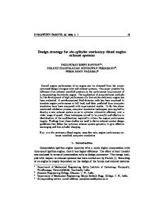
Figure 16: Dynamic verification of the non-minimum phase between uegr and pin using steps. Operating point: ωe = 1500 rpm, Te = 670 Nm, uvgt = 0.5 ratio. Fig. 17 shows that the model capture the nonminimum phase behavior between the VGT position, uvgt , and the compressor mass flow m˙ c . Notice that initially the DC gain between uvgt and m˙ c is negative Figure 18: Slow sweep of the uvgt from fully open tobut after a while it becomes positive. This phenom- wards closed position. Operating point: ωe = 1500 ena is even better seen in Fig. 18 where the uvgt is rpm, Te = 670 Nm, uegr = 1 ratio. DOI 10.3384/ecp12076101
Proceedings of the 9th International Modelica Conference September 3-5, 2012, Munich, Germany
109
Gas Exchange and Exhaust Condition Modeling of a Diesel Engine using the Engine Dynamics …
5.4
Dynamic validation
The engine system model is validated with JE05 boundary conditions using the experiment setup in Fig. 9. The cycle is 1830 seconds long and the simulation time for the whole cycle was 735 seconds (2.5x faster than real-time) on a standard laptop. The JE05 is a very transient cycle which contains mostly city drivFigure 21: Complete model validation. Exhaust ing with some high way driving. The engine speed gas temperature [K], simulated (solid) and measured variations during the complete cycle are shown in Fig. (dashed) 19 and the load variations are shown in Fig. 20.
Figure 19: JE05 engine speed [rpm]
Figure 22: Complete model validation. Exhaust NOx concentration [kg/kg], simulated (solid) and measured (dashed) Figures 23 - 27 show simulation results for engine torque, mass flow rates and exhaust gas temperature from a part of the cycle (750 - 1000 s). The exhaust gas temperature is measured in the pipe 1 meter after the turbine. As can be seen in Fig. 23 the model captures most of the behavior. Figures 24 - 26 show that the model captures the dynamics of the exhaust, EGR and air mass flows. The ERG flow in Fig. 25 shows a small time lag of the measured flow compared to the simulated. This is likely due to a time lag in the EGR flow sensor.
Figure 20: JE05 engine torque [Nm]
The resulting full cycle exhaust gas temperature is shown in Fig. 21 and NOx emissions are shown in Fig. 22. Both the modeled exhaust temperature and the NOx emission captures most of the behavior. The modeled exhaust temperature differs from the measured temperature in the end of the JE05 cycle. The temperature before the VGT capture the temperature behavior correct also in the end of the cycle this indi- Figure 23: Complete model validation. Exhaust cate that there are still heat transfer effects that need to gas temperature [K], simulated (solid) and measured be incorporated in the model. (dashed) 110
Proceedings of the 9th International Modelica Conference September 3-5, 2012, Munich Germany
DOI 10.3384/ecp12076101
Session 1C: Power and Energy
torque (Fig. 27). The difference may be explained by the fact that the friction or the pumping loss measurements which the model is based on are not correct in this region. Fig. 28 shows the NOx emissions. The black-box model succeeds to capture the behavior. The NOx levels are quite close to the measured level in steady state operation, and the peaks are often quiet close to the measured level regarding timing and level. The NOx Figure 24: Complete model validation. Exhaust level was measured by a Horiba system, which isn’t gas flow rate [kg/s], simulated (solid) and measured capable of measuring fast transients and the measure(dashed) ments can be regarded as a filtered values.
Figure 25: Complete model validation. EGR flow rate Figure 28: Complete model validation. Exhaust NOx [kg/s], simulated (solid) and measured (dashed) concentration [kg/kg], simulated (solid) and measured (dashed)
6
Figure 26: Complete model validation. Air flow rate [kg/s], simulated (solid) and measured (dashed)
Figure 27: Complete model validation. Engine torque [Nm], simulated (solid) and measured (dashed) The model captures most of the dynamics of the engine torque, but for the idling part (e.g. 850-890s) there is an offset between modeled and measured DOI 10.3384/ecp12076101
Discussion
The components in the 13L Volvo PNLT engine are primarily modeled by a physical first-principle approach. The selected inputs for the emission model does not capture the effect of the wall temperature and a next step can be to parametrize a cylinder wall temperature model in order to model the effects of cold starts. The current simple emission model captures most of the transient effects and in order to further improve the transient optimization based on the models the accuracy needs to be improved. Instead of assuming CO2 in the exhaust manifold based on stoichiometric combustion, it can be added as an output of the emission model. This may improve the estimation of the CO2 in the inlet manifold which is one of the inputs to the emission model. There exists several data driven emission models with similar computational complexity that would be interesting to compare against [16]. The plan for the future is that EDL will be expanded with more combustions model options, including cycle-resolved in-cylinder behavior. By introducing the effects of pressure pulses and improving the internal loss model, the turbo model can also be further improved.
Proceedings of the 9th International Modelica Conference September 3-5, 2012, Munich, Germany
111
Gas Exchange and Exhaust Condition Modeling of a Diesel Engine using the Engine Dynamics …
JModelica.org was used for the optimization of parameters for the heat transfer and thermal dynamics and Dymola was used to export the FMU model. JModelica has extended the Modelica language for increased optimization functionality. The derivative-free simplex method used worked very well for parameter optimization for a model of this complexity without requiring any model modifications. Other tools also exists that can perform calibration using similar methods, for example the model calibration feature in Dymola or Isight. Isight was also tested for the same optimization task and the simplex method available there gave equivalent results to JModelica regarding optimization time and result. The simulation speed is about 2.5 times faster than real-time using the Dymola integrated Radau solver. This is a variable step-length solver, and the fast average simulation speed does not guarantee that the current model can be used in applications with hard realtime requirements, but this was not in the scope for this model. For hard real-time simulations, fixed-step solvers must be used. This introduces harder requirements on the model regarding fast dynamics and function evaluation time. As the models of the PNLT engine managed to capture the engine out conditions and the dynamical behavior in the air gas path, the model can be used to develop engine control strategies that reduce the requirement on the EATS. With transient control strategies that reduce transient emissions, the EATS volumes (e.g. DOC, DPF and SCR) may be reduced. Also by adapting the engine control strategies based on the condition of the EATS (e.g. temperature, aging and poisoning) the EATS volumes may be reduced. The fuel cost of the different engine control actions depends significantly on the engine hardware and each has an optimal trade-off between fuel cost and product cost. Engine models based on EDL together with a SIL environment which includes the control strategies is a powerful approach in the investigation of finding the optimal trade-off.
an engine screening where measurements are made to isolate the different components. Therefore a component can be replaced without any need of a new complete engine screening, allowing for virtual prototyping of new concepts. This is an important advantage compared to black-box modeling of the complete engine, which would require a complete new screening when changing a single component. Finding parameter values for the heat transfer and thermal dynamic in the exhaust that matches measurements is an optimization problem that has been solved using JModelica. The parameters were successfully optimized resulting in good estimation of the exhaust temperature dynamics. The models captured the essential system properties in the gas exchange such as non-minimum phase behavior and sign reversal. As the exhaust mass flow, exhaust temperature and emissions were shown to be well captured the model can be used in order to evaluate control strategies of the air gas management and to find a trade-off between fuel-economy, transient response, engine emissions and EATS requirements. The system identification of the NOx emissions gave good results in the operating area of the JE05 cycle and captured the trends. This indicates that the selected inputs to the emission model contain most of the entities that affect the emissions. Using variable step-length solvers, the engine model simulates faster than realtime for the JE05 cycle. This is a very transient cycle, and therefore the expectation is that other transient cycles will also simulate with real-time like simulation times.
References [1] T. Johnson Diesel Emissions in Review, SAE Technical Paper 2011-01-0304, 2011. [2] R. Cloudt and F. Willems. Integrated Emission Management strategy for cost-optimal engineaftertreatment operation, SAE Technical Paper 2011-01-1310, 2011. [3] Dymola User Manual, Volume 1, Lund, 2011
7
Conclusions
In this article it has been demonstrated that the newly developed Engine Dynamics library and Dymola can be used for simulation of the gas exchange, transient flow and temperatures and emission trends for a 13L Volvo PNLT engine. All components and parameters have been calibrated component wise without any global compensation. Calibration data comes from 112
[4] J. Batteh, M. Tiller and C. Newman. Simulation of Engine Systems in Modelica, Proceedings of the 3rd Modelica Conference, Linköping, Sweden, 2003. [5] A. Picarelli and M. Dempsey. Investigating the Multibody Dynamics of the Complete Powertrain System, Proceedings of the 7th Modelica Conference, Como, Italy, 2009.
Proceedings of the 9th International Modelica Conference September 3-5, 2012, Munich Germany
DOI 10.3384/ecp12076101
Session 1C: Power and Energy
[6] L. Guzzella and C.H. Onder. Introduction to Modeling and Control of Internal Combustion Engine Systems, 2nd edition, 2010. ISBN 9783-642-10774-0.
NOX and Soot Emissions from a Diesel Engine. SAE Technical Paper 2012-XX-0351, 2012.
[7] R. Johansson. System modeling & Identification, 2009. ISBN 0-13-482308-7. [8] HIH Saravanamuttoo, GFC Rogers and H Cohen. Gas Turbine Theory, Fifth Edition, 2001. ISBN 978-0-13-015847-5. [9] B.J. McBride, M.J. Zehe and S. Gordon. NASA Glenn Coefficients for Calculating Thermodynamic Properties of Individual Species. NASA report TP-2002-211556, 2002. [10] J. D’Errico. Understanding GRIDFIT, 2006. Available for download at http://www.mathworks.com/matlabcentral/ fileexchange/8998 (last accessed 20120228). [11] J. Åkesson, K-E. Årzén, M. Gäfvert, T. Bergdahl and H. Tummescheit. Modeling and Optimization with Optimica and JModelica.org - Language and Tools for Solving Large-Scale Dynamic Optimization Problems, Computers and Chemical Engineering, 34:11, pp. 1737-1749, November 2010 [12] S. Gedda. Calibration of Modelica models using derivative-free optimization, Master’s thesis 2011:E46, Lund University, Faculty of Engineering, Centre For Mathematical Sciences, Mathematics, 2011. [13] S. Gedda, C. Andersson, J. Åkesson and S. Diehl. Derivative-free Parameter Optimization of Functional Mock-up Units. In 9th International Modelica Conference, 2012. [14] MODELISAR(07006). Functional Mock-up Interface for Model Exchange Available for download at: http://www.functional-mockupinterface.org/ (last accessed 20120228). [15] J. Wahlström and L. Eriksson. Modeling of a diesel engine with VGT and EGR capturing Sign Reversal and Non-minimum Phase Behavior. Proceedings of the Institution of Mechanical Engineers, Part D, J. of Automobile Engineering, Volume 225, Issue 7, July 2011. [16] M. Grahn and T. McKelvey. MA Structure and Calibration Method for Data-driven Modeling of DOI 10.3384/ecp12076101
Proceedings of the 9th International Modelica Conference September 3-5, 2012, Munich, Germany
113
Gas Exchange and Exhaust Condition Modeling of a Diesel Engine using the Engine Dynamics …
114
Proceedings of the 9th International Modelica Conference September 3-5, 2012, Munich Germany
DOI 10.3384/ecp12076101