Frequently asked questions about phase detectors (AN-41-001) ______________________________________________________________________ Q. Among Mini-Circuits products, what is the difference between a phase detector and a double-balanced mixer (DBM)? A. They are physically similar, but each type of product is specified on its data sheets in accordance with its principal application. The range of DBMs offered is greater in frequency range and choice of power levels. Therefore, system designers might find it advantageous to utilize a DBM as a phase detector, as long as its IF frequency range goes down to DC. For generality in the questions and answers that follow, the term “DBM” refers to both a Mini-Circuits product described as a double-balanced mixer, and one that is described as a phase detector. “LO and RF” are respectively denoted as “RF REF and RF IN” or as “RF2 and RF1” in phase detector applications. Q. A couple of diodes can be hooked up as a phase detector. Why go to the expense of using a DBM for the same function? A. A DBM type of device is ideal for phase detection since it offers high isolation between all three ports: the reference (LO), input signal (RF) and output (IF). Furthermore, the DBM provides very low DC offset or residual voltage at the IF output. Q. Can you explain, briefly, how a DBM works as a phase detector? A. When a DBM is used as a phase detector, this is merely a special case of mixing action where the LO and RF signals are at the same frequency. Now, let's look at the mixer equation: IF output = A1 cos [(ωLO – ωRF)t – (ØLO – ØRF)] + A2 cos [(ωLO + ωRF)t – (ØLO + ØRF)] + [higher-order frequency terms] In a phase detector application, ωLO = ωRF ; therefore, in the first part of each term, ωLO ωRF = 0 and the IF output is only a function of A1 cos (ØRF – ØLO) + A2 cos (2ωt) plus higher frequency terms. With proper filtering, the (2ωt) terms and higher can be eliminated so the IF output is equal to Al cos (ØRF – ØLO). When the difference between the RF and LO phase angles is ±90°, the IF output voltage is zero. When the difference is 0° the output is the maximum positive value. When the difference is 180° the output is the maximum negative value. In some models including those specifically designated as phase detectors, the polarity is reversed. If polarity is important in your application and it is not specified for the DBM you want to use, please consult the factory.
AN-41-001 Rev.: A (04/14/15) M150261 File: AN41001.doc This document and its contents are the property of Mini-Circuits.
Sheet 1 of 7
Q. What are the important specifications of a phase detector? A. Important electrical specifications of a phase detector, including a DBM used in a phase detector application, are: (1) DC offset (2) maximum DC output (DC output occurring with in-phase signals) (3) isolation between ports (4) polarity of output voltage (5) frequency response (variation of maximum DC output with input frequency) (6) temperature variation of DC offset Q. Is there any difference in the frequency range spec when a DBM is used as a phase detector compared with its use as a mixer? A. Yes. The frequency specs for RF apply to a DBM operating in an unsaturated mode. When used as a phase detector, the DBM is operating in a saturated mode, which tends to shrink the bandwidth. Thus, to be conservative when using a DBM as a phase detector, select a mixer with a bandwidth 1.5 times wider than the unsaturated specs. For example, if your phase detector application covers 1-500 MHz, select a mixer whose RF port specification is at least 0.66-750 MHz. Q. I intend to use an op amp following the phase detector. What problems might I face? A. There are three potential problems. (1) Although the op amp should ideally have zero DC volts at its input, it can actually have some small DC voltage. Thus, when the op amp is connected to the output of the phase detector, this voltage can improperly bias the diodes in the phase detector and cause an unbalance in the diode circuit. (2) Uncertain amount of DC output voltage, due to uncontrolled load resistance. To obtain the specified DC output from the phase detector it is necessary to provide 500-ohm DC load impedance. (3) Overload of the op amp or subsequent circuits due to lack of proper filtering of highfrequency spectral components from the phase detector, especially the component which is the sum of the RF input frequencies. A solution to remedy these problems involves a simple RC filter as shown. Since the op amp has very high input impedance, the 5 k-ohm series resistor does not attenuate the DC output from the phase detector. Also, any small DC voltage at the op amp is attenuated by 11:1 (by the 5 k-ohm and 500-ohm resistor combination) at the phase detector output. Finally, the RC combination acts as a low pass-filter to attenuate the sum frequencies; if additional filtering is required, a multiple-section RC filter can be used.
AN-41-001 Rev.: A (04/14/15) M150261 File: AN41001.doc This document and its contents are the property of Mini-Circuits.
Sheet 2 of 7
Q. Is it necessary to provide a filter at the output of the phase detector? A. In many cases, yes. The RF1-plus-RF2 term (ω1 + ω2, or 2ω when the frequencies are equal) must be removed since it may cause system degradation. Without a filter the high frequency terms in the DC (IF) output can leak into the system and cause amplifier saturation or other undesired results. Q. Does a phase detector such as SYPD or ZRPD series require a 500-ohm load? A. The DC output port is approximately a current source. If a lower load resistance is used, such as 50 ohms, the voltage will be less. If the load resistance is higher, somewhat more voltage can be obtained. To obtain the DC Output voltage shown on the data sheet, 500 ohms has to be used. The 500-ohm load, returned directly to ground, tends to keep any small DC voltage from a subsequent op amp from improperly biasing the diodes in the phase detector. Q. Why must the DBM be operated in a saturated mode when used as a phase detector? A. When sufficiently high input level signals are applied to the LO and RF ports, the DBM operates in a saturated mode (as a limiter) and thus the IF output becomes nearly independent of input signal level variations. Thus, the IF output of the DBM would have a DC voltage proportional only to the phase difference between LO and RF inputs. Q. Data sheets of phase detectors indicate that both input signals, RF and LO (or RF1 and RF2) should be equal in amplitude. What happens if they are not? A. If the signal inputs to the LO and RF ports are of sufficient magnitude, the phase detector will operate in a saturated mode and provide a DC output proportional to the phase difference between the two signals. However, if the LO signal is of sufficient amplitude but the RF signal is low in amplitude, the output of the phase detector will be proportional to the amplitude as well as the phase of the RF input. To operate the DBM in the required saturated mode, the RF signal level should be at least: +1 dBm for Standard Level (+7 dBm LO) mixers +10 dBm for High Level (+17 dBm LO) mixers +15 dBm for Very High Level (+23 dBm LO) mixers. Q. Why is DC offset so important in a phase detector? A. In many phase detector applications, one of the two signals may be 90° out of phase with the other. Theoretically, the phase detector output would be zero volts. However, there will be a slight DC output due to the offset voltage. This would then be interpreted as a phase difference that is other than 90°. Thus, the lower the DC offset voltage, the more accurately the phase detector performs its function.
AN-41-001 Rev.: A (04/14/15) M150261 File: AN41001.doc This document and its contents are the property of Mini-Circuits.
Sheet 3 of 7
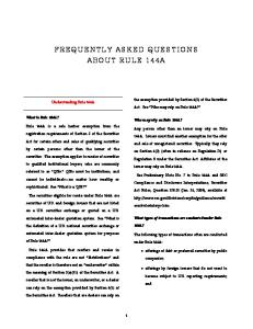
Q. How is DC offset voltage of a phase detector measured? A. It can be measured statically or dynamically. For a static measurement, terminate the RF port with 50 ohms and apply a signal only to the LO input. Measure the DC at the IF port through a low-pass filter; this is the DC offset voltage. A disadvantage of the static approach is that any DC offset contributed by the RF input signal is not included. In a dynamic test, an RF input signal and an LO signal of equal amplitude are applied to their respective ports, with the RF signal slightly offset (10 kHz) from the LO. Then a low pass filter is connected to the IF port to eliminate all frequency components including the 10 kHz difference frequency. Now, the DC offset voltage reading at the low-pass filter output is more accurate because it is measured under operating conditions that are typical of phase detector applications. The graph below compares the results using the two methods. DC Offset Voltage: Static vs. Dynamic Method Model ADEX-10L: 3 typical samples, RF Power 4 dBm 0.3 0.25
Output Voltage, mV
0.2 0.15 #-2 static
#-8 static
#-9 static
#-2 dynamic
#-8-dynamic
#-9 dynamic
0.1 0.05 0 50
60
70
80
90
-0.05
100
110
120
130
140
150
160
170
180
Frequency, MHz
-0.1 -0.15
Q. How is DC offset affected by temperature? A. If only one input is present, say LO, there should be zero output. However, due to slight mismatch in the diodes and imperfect balance in the transformer windings, a small DC voltage will appear at the IF output. This is called the DC offset voltage.
AN-41-001 Rev.: A (04/14/15) M150261 File: AN41001.doc This document and its contents are the property of Mini-Circuits.
Sheet 4 of 7
The value of the DC offset varies with temperature. Over a wide temperature range the unbalance of the mixer diodes can cause DC offset, with slight contribution from the transformer. An effective technique to minimize DC offset variation with temperature is to use diodes whose characteristics track with temperature. This is accomplished at Mini-Circuits by integrating the diodes on the same semiconductor die. Also, MiniCircuits employs specially designed winding machines so that the assembled transformers have well-matched windings. The net result: Mini-Circuits offers ultra-low DC offset characteristics over a wide temperature range. For the graph below, DC offset was measured at three temperatures by the static method (see previous Q&A for definition) on two samples having different amounts of DC offset, to indicate the typical range that might occur. DC Offset Voltage: Temperature Effect Model ADEX-10L: 2 Samples, LO Power 4 dBm 0.5
Output Voltage, mV
0.4
0.3
0.2 0°C
25°C
70°C
0.1
0 45
65
85
105
125
145
165
185
-0.1 Frequency, MHz
Q. Suppose the DC output of a DBM is insufficient for my phase detector application. What do you suggest? A. Use a higher level mixer than you had selected. Or specify one of Mini-Circuits RPD series of high "figure-of-merit" phase detectors. Or, use an op amp. Q. I want to compare the phase of two square waves. Do I have to convert them to sine waves before applying them to a phase detector? A. No. Since the phase detector operates in a saturated mode and tends to square up a sine wave, it is not necessary to alter the square wave inputs.
AN-41-001 Rev.: A (04/14/15) M150261 File: AN41001.doc This document and its contents are the property of Mini-Circuits.
Sheet 5 of 7
Q. Isolation specs for LO to RF and LO to IF are generally included in mixer specs, but RF to IF isolation is often not listed. What are typical values? A. In a mixer application, the RF signal level is generally very low and thus the RF-IF isolation parameter is unimportant. However, in a phase detector application, the RF level is high and thus the RF-IF isolation becomes important. As a rule of thumb, LO-IF isolation is generally less than LO-RF isolation 10 dB less at low frequency, 15-20 dB less at mid- and high-frequency. Q. What are the basic steps to select the proper phase detector? A. First, decide on the maximum DC output needed. Next, select a phase detector with adequate bandwidth. Then decide on the required isolation and make sure the detector you select meets the requirement. Finally, if phase accuracy is critical, specify the maximum DC offset tolerable for the intended frequency range. Q. What is the performance characteristic of a phase detector? A. The DC output voltage of a phase detector varies according to the phase difference between the RF inputs at the Reference and RF ports. It has maximum values, positive and negative, when the inputs are in-phase and out-of-phase. The DC voltage passes through zero at 90° phase difference. When the two RF inputs have equal power, 7 dBm as specified in the data sheets of the MPD, RPD, SYPD and ZRPD models, the characteristic is nearly linear between the 0° and 180° points. Such a characteristic is described as a triangular waveform. If one of the RF signals inputted to the phase detector is much lower in power than the other, in the manner of a DBM used as a mixer, the phase detector characteristic is sinusoidal. In that case, the phase-detector scale factor (also known as its sensitivity) is much less, and it decreases further as the phase difference departs from 90°. Q. How can I determine the scale factor of a phase detector, especially if I use it at different power levels or if I use a mixer as a phase detector? How does it affect the loop gain of my phase-lock loop (PLL)? A. The data sheet of our RPD-1, for example, specifies 8 mV per degree as the typical scale factor. This is for the conditions 7 dBm applied to each of the two RF input ports, and 500-ohm shunt load at the DC OUT port. It is equivalent to (8 mV) x (0.001 V/mV) x (360/2π degrees per radian) = 0.458 volts per radian, which are the units generally used in PLL loop gain calculation. If you want to measure the scale factor, you can do it by applying to the phase detector two signal sources having a small frequency difference, each signal being at the actual power level you are planning to use in your PLL application. Observe the output on an oscilloscope. It should look sinusoidal if one signal is several dB less than the other, or nearly triangular if both are high (such as 7 dBm each). Measure the slope on the oscilloscope where the trace passes through zero volts. That slope is the scale factor. Caution: do not let the frequencies be so close together that the signal sources pull AN-41-001 Rev.: A (04/14/15) M150261 File: AN41001.doc This document and its contents are the property of Mini-Circuits.
Sheet 6 of 7
toward injection-locking to one another, because that will distort the waveform and make the measurement inaccurate. Mathematically, if the peaks of a sinusoidal waveform are +V and -V, the slope is V volts per radian. If the peaks of a triangular waveform are +V and -V, the slope is 2V/π volts per radian. If you find that the shape of the waveform is in-between sinusoidal and triangular you can take the average of these results, which is (V + 2V/π) / 2 = 0.82 × V volts per radian. Q. Is the DC polarity output of a phase detector fixed by the manufacturer or can the polarity be reversed at the user's discretion? A. Mini-Circuits phase detectors are manufactured to provide a negative output when in-phase signals are applied. If the user requires a positive DC output, some phase detector models allow the user to reverse the connections at the reference port. Examples are MPD-1 and RPD-1, for which external connections to Pins 7 and 8 would be reversed. Or, a mixer having positive DC output (when used as a phase detector) can be chosen. If polarity is not specified, please consult the factory.
IMPORTANT NOTICE © 2015 Mini-Circuits This document is provided as an accommodation to Mini-Circuits customers in connection with Mini-Circuits parts only. In that regard, this document is for informational and guideline purposes only. Mini-Circuits assumes no responsibility for errors or omissions in this document or for any information contained herein. Mini-Circuits may change this document or the Mini-Circuits parts referenced herein (collectively, the “Materials”) from time to time, without notice. Mini-Circuits makes no commitment to update or correct any of the Materials, and Mini-Circuits shall have no responsibility whatsoever on account of any updates or corrections to the Materials or Mini-Circuits’ failure to do so. Mini-Circuits customers are solely responsible for the products, systems, and applications in which Mini-Circuits parts are incorporated or used. In that regard, customers are responsible for consulting with their own engineers and other appropriate professionals who are familiar with the specific products and systems into which Mini-Circuits’ parts are to be incorporated or used so that the proper selection, installation/integration, use and safeguards are made. Accordingly, Mini-Circuits assumes no liability therefor. In addition, your use of this document and the information contained herein is subject to Mini-Circuits’ standard terms of use, which are available at Mini-Circuits’ website at www.minicircuits.com/homepage/terms_of_use.html. Mini-Circuits and the Mini-Circuits logo are registered trademarks of Scientific Components Corporation d/b/a Mini-Circuits. All other third-party trademarks are the property of their respective owners. A reference to any third-party trademark does not constitute or imply any endorsement, affiliation, sponsorship, or recommendation: (i) by Mini-Circuits of such third-party’s products, services, processes, or other information; or (ii) by any such third-party of Mini-Circuits or its products, services, processes, or other information. AN-41-001 Rev.: A (04/14/15) M150261 File: AN41001.doc This document and its contents are the property of Mini-Circuits.
Sheet 7 of 7