FRACTURE TOUGHNESS OF A LAMINATED COMPOSITE Sharon Kao-Walter, Dept of Mechanical Engineering, Blekinge Institute of Technology, Karlskrona, Sweden, e-mail:
[email protected] Per Ståhle, Div. of Solid Mechanics, Malmö University, Malmö, Sweden, e-mail:
[email protected] Rickard Hägglund, SCA Research AB, Sundsvall, Sweden, e-mail:
[email protected] ABSTRACT The fracture toughness of a polymer-metal laminate composite is obtained by mechanical testing of a specimen containing a pre-crack. The laminate is a material used for packaging. It consists of a thin aluminium foil and a polymer coating. A centre cracked panel test geometry is used. Each of the layers forming the laminate is also tested separately. The result is compared with the measured fracture strength of the individual layers. It is observed that the load carrying capacity increases dramatically for the laminate. At the strain when peak load is reached for the laminate only aluminium is expected to carry any substantial load because of the low stiffness of the LDPE. However, the strength of the laminate is almost twice the strength of the aluminium foil. The reason seems to be that the aluminium forces the polymer to absorb large quantities of energy at small nominal strain. The toughness compares well with the accumulated toughness of all involved layers. Possible fracture of the interface between the layers is discussed. KEYWORDS Laminate, aluminium foil, polymer, crack, fracture toughness INTRODUCTION Liquid food packages are often made of packaging materials consisting of different material layers to fulfil several requirements of the package. It is very important to ensure that every layer maintains its function during the forming, filling and transportation processes. As an example here a liquid food packaging material is considered. This is a laminate consisting of LDPE (Low Density Polyethylene) and an aluminium foil (Al-foil). Several studies of different mechanical properties of these materials have been performed [1-5]. It was found in [2] that aluminium foil and LDPE laminated together provide significantly higher stress and strain at fracture as compared with the simplified analytical prediction. Related works can also be found in [6], [7], [8] where notched tensile strength, fracture toughness as well as fatigue resistance for fiber/aluminium composite laminate were studied. The purpose of this work is to study the fracture toughness of a laminated material in relation to the adhesion between the layers. Load and extension were measured for a two-layer laminate specimen with a pre-crack as well as for the individual layers of the laminate. The same specimen geometry was used in all tests. For comparison, measurements were also done for the laminate without any adhesion between the layers.
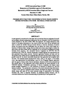
MATERIAL Laminate in this work consists of Al-foil and Low Density Polyethylene (LDPE). Fully annealed AA1200 Al-foil and LDPE with the product name LD270 is used. Load versus extension were measured for the following materials: Case 1: Al-foil with the thickness 8.98 µm. Case 2: LDPE with the thickness 27.30 µm. Case 3: Al-foil / LDPE – Al-foil coated by LDPE and the total thickness is 36.28 µm. Case 4: Al-foil // LDPE – Al-foil and LDPE joined together without adhesion between the layers and the total thickness is 36.28 µm. Here “/” applies to two material layers bonded together and “//” applies to two layers put together without any adhesion in between. For case 3, pieces of Al-foil were cut from a roll of fabricated material as shown in Fig.1(a). The laminate in case 3 was then prepared in a Haake film extruder with a 36 µm Polyester (PET) as carrier (see Fig.1(b)). The foil was mounted on the PET carrier while LDPE was extruded and coated on Al-foil at a melting temperature of 278 oC. A nip with the pressure 202 bar was used to press the layers together. The laminated specimen for case 3 was than cut from roll including PET/Al-foil/LDPE as shown in Fig.1(c). After producing the material for case 3, LDPE was continuously extruded on the PET carrier under the same conditions but without the Al-foil. By peeling off the PET carrier, the LDPE produced here was used for making the specimen for case 2 and case 4. And the specimen of case 1 is taken from the Al-foil roll of the same direction as the other cases.
Extruder
Melted LDPE
LDPE/Al-foil/PET
PET carrier
Al-foil
PET (c)
(b) Fig.1. Schematic description of specimen preparing.
(a)
EXPERIMENTAL METHOD Centre cracked panels as shown in Fig.2(a) are used for evaluating the fracture toughness of the laminated composite and components of it. Pre-fabricated cracks are manually cut, using a razor blade, to a total slit length of 2a = 45 mm. The width and gauge length of the specimens was 2W = 95 mm and 2h = 230 mm, respectively. A pair of wide clamps is utilised, see Fig.2(b). The tests are made in a MTS Universal Testing Machine. The upper clamp is attached to a 2.5 kN load cell as well as a crosshead in the MTSmachine. Since the specimen is mounted vertically, the clamps are equipped with needles to facilitate a correct positioning. After the positioning of a sample the upper and lower clamps are closed and the pressure is applied by tightening four equally spaced quick-acting locking nuts along the front of each clamp, see Fig.2(b). Locking pins at the centre of the front jaws keep the clamps in an open position during mounting. The largest sample that can be accommodated is 420 mm wide. Specimens are tested by traversing the upper crosshead up to move the sample under increasing tension u at a constant crosshead speed of 9.2 mm/min. The software TestWorks is used to control the load frame and also to record data. During testing both displacement between the crossheads and load is monitored and recorded. All tests are run until the entire cross section has fractured.
u/2
2h 2a 2W
u/2 (a). Centre cracked panel.
(b). Set-up for fracture mechanical testing of laminated composites. The specimen shown here is case 4. Fig. 2. Specimen and experiment set up.
ANALYTICAL APPROACH ELASTIC BEHAVIOUR OF THE SPECIMEN The force elongating the specimen may be separated into that of the unbroken specimen, Po, and the reduction, Pc, due to the presence of a crack. The former is calculated as follows: Po =
uEWt h
,
(1)
and the latter is obtained from the energy, Uc, released during the cutting of a crack [6]: Uc =
t E
a
∫ 0 KI2da′
.
(2)
The stress intensity factor for the crack is given by
KI =
uE h(1− ν 2 )
φ (a /W ).
(3)
This gives the energy 1 u 2 EWt U c = uPc = 2 4h(1− ν 2 )
a /W
∫ φ (τ )dτ .
(4)
0
Using φ given in [9] the integral of (4) is found to be 0.08 for a/W = 0.47. With W = 47.5 mm and h = 115 mm (1), (3) and (4) give uEWt 1 P = Po − Pc = 1 + h 2(1 − ν 2 )
a /W
0
∫ φ (τ )dτ
(5)
giving P = 0.92
uEWt . h
(6)
Thus, the stiffness of specimen decreases only 8% as compared with a corresponding unbroken specimen. CRACK TIP DRIVING FORCE G According to the theory of fracture mechanics, a crack tip driving force G is defined as the rate of change in potential energy per crack area and per unit of length of crack front [10, 11]. It is assumed that the critical driving force, Gc, of a crack in a single layer is constant and independent of whether the layer is bonded to other layers or not. Assuming that no delaminating occurs during the growth of a crack in the laminate and that energy is not dissipated in the material, the crack tip driving force for the laminate is the accumulated driving force for all layers, i.e.
G=
G1t1 + G2t 2 t1 + t 2
(7)
Here the assumption that G = GC as crack growth criterion is examined. This criterion is valid if the crack grows in an approximate steady state. The load at onset of crack growth is usually regarded to define the fracture toughness. For materials with considerable toughening the incipient growth of the crack leads to increased fracture toughness. At small scale yielding the maximum toughness may be of interest but in the present analyses the yielding is considerable. There is a difficulty to define onset of crack growth since the observation is that the crack grows in the Al-foil until the crack traverses the entire specimen before there is any substantial crack growth in the LDPE layer. PEAK LOAD Fm AND DISSIPATED ENERGY U For practical use the maximum load carry capacity may be limiting the reliability of the packaging structure. Therefore it is interesting to compare peak load both for each material separately and as a laminate. It is also interesting to examine the energy dissipated before breaking is reached. The dissipated energy, U, is found from the load displacement curve, P(δ) as follows δ
dP δ2 U = ∫ P( τ )dτ − dδ dδ