Piston type, screwed
for Manufacturing and Building Equipments etc. Piston-type solenoid valve PS series piston-type screwed solenoid valves for energized open and energized close operation.
FEATURES Free installation in vertical or horizontal direction (size 10~50mm). Energized open or energized close operation.
For steam, water, air, and oil. Wide range of working pressure: 0~1.0MPa
SPECIFICATIONS Energized open
Operation
Energized close
Model name
PS-12
PS-12C
Code name
PS12-W
PS12C-W
Steam, water, air & oils(Kerosene, light oil, gasoline level)
Applicable fluid
0~1.0MPa
Applicable pressure Min. pressure differential across the disc
0MPa (0.03MPa for coil installed horizontally.) 5~180℃ (For hot water:Max. 100℃)
Fluid temperature Fluid viscosity
20cSt or less Steam, water & oils:Nil (Confirm at pressure gauge)
Leakage allowance
Air:50ml/min(standard state) or less (when 0.05~1.0MPa) Common use:AC100/200V 50/60Hz or AC110/220V 60Hz*3.
Rated voltage Insulation
Class H (Silicone mold) 5~60℃
Ambient temperature Protection
Dust & drip proof (When used outdoors, also use TB-03 Type terminal box, as rain proof type)
End connection
Screwed JIS Rc
Materials
Body(Cast bronze), Disc(Stainless steel with Teflon tip) Size 50mm or smaller:Can be installed on both horizontal and vertical piping at any angle between the vertical (when the coil part is placed above) and horizontal. Size 65mm:Install the valve vertically in horizontal piping placing coil part above.
Installation
Hydraulic 2.0MPa
Valve body pressure
* 1. Refer to page 231 for Method of Wiring. * 2. In case complete of shut off is required for air service, or the valve is used for well water, select WS or WF series. * 3. Special voltage items other than the above specified are available upon your request. * 4. We also provide PS-12Z type, which size is smaller than 25mm and is suitable for applications requiring highly frequent opening/closing. * 5. Select PS-12Y, 12CY types if humidity is higher than 85%. * 6. We also provide PS-12R type that is suitable for oil or other fluid with viscosity up to 100cSt (the specifications may vary slightly for sizes smaller than 50mm) .
DIMENSIONS AND CURRENT VALUES Size L G H
PS-12 Type
10( ⅜" )
15( ½" )
20( ¾" )
25(1 " )
⅜"
½"
¾"
1"
32(1 ¼" ) 40(1 ½" ) 1¼"
1½"
50(2 " ) 2"
65(2 ½" ) 2½"
63
63
80
90
106
118
140
160
15
15
18
22
27
30
37
45
118(177) 118(177) 130(186) 136(191) 147(201) 150(204) 162(216) 200(252)
Port size
18
18
23
28
32
40
48
Cv value
3
4.5
7.5
12
18
23
35
50
Mass(kg)
1.2(1.8)
1.1(1.7)
1.6(2.1)
2.1(2.6)
2.8(3.3)
3.6(4.1)
5.3(5.8)
8.1(8.5)
AC100V Current (A) AC200V
60
Rated
0.20(0.30)
0.25(0.30)
0.35(0.40)
0.60(0.60)
Starting
0.60(1.30)
0.90(1.30)
1.30(1.70)
2.50(2.50)
Rated
0.10(0.15)
0.13(0.15)
0.18(0.20)
0.30(0.30)
Starting
0.30(0.70)
0.45(0.70)
0.65(0.85)
1.25(1.25)
Figures in ( ) are for PS-12C Type
CONSTRUCTION PS-12 Type
PS-12C Type
PS-12C Type Note: Depending on size, the structure may vary.
Piston type, flanged
PF series piston-type flanged solenoid valves for energized open and energized close operation applications.
FEATURES Free installation in vertical or horizontal direction (size 15~50mm). Energized open or energized close operation.
For steam, water, air, and oil. Wide range of working pressure: 0~1.0MPa.
SPECIFICATIONS Energized close
Energized open
Operation
PF-12C
Model name
PF-12
Code name
PF12-W*
1
PF12C-W*
1.
Steam, water, air & oils(Kerosene, light oil, gasoline*5. level)
Applicable fluid
0~1.0MPa(0.05~1.0MPa for size 80mm.)
Applicable pressure Min. pressure differential across the disc
0MPa (0.03MPa for coil installed horizontally. 0.05MPa for size 80mm.) 5~180℃ (For hot water:Max. 100℃)
Fluid temperature
20cSt or less
Fluid viscosity
Steam, water & oils:Nil (Confirm at pressure gauge)
Leakage allowance
Air:50ml/min(standard state) or less (when 0.05~1.0MPa) Common use:AC100/200V 50/60Hz or AC110/220V 60Hz*4.
Rated voltage Insulation
Class H (Silicone mold) 5~60℃
Ambient temperature Protection
Dust & drip proof (When used outdoors, also use TB-03 Type terminal box, as rain proof type)
End connection
Flanged JIS 10KFF
Materials
Body(Cast bronze, Size 80mm:Cast iron), Disc(Stainless steel with Teflon tip) Size 50mm or smaller:Can be installed on both horizontal and vertical piping at any angle between the vertical (when the coil part is placed above) and horizontal. Size 65· 80mm:Install the valve vertically in horizontal piping placing coil part above.
Installation
Hydraulic 2.0MPa
Valve body pressure
* 1. Code name for size 80mm are PF12-S and PF12C-S. * 2. Refer to page 231 for Method of Wiring. * 3. In case complete of shut off is required for air service, or the valve is used for well water, select WS or WF series. * 4. Special voltage items other than the above specified are available upon your request * 5. We also provide PF-12Z type, which size is less than 25mm and is suitable for applications requiring highly frequent opening/closing. * 6. Select PF-12Y, 12CY types if humidity is higher than 85%. * 7. We also provide PF-12R type that is suitable for oil or other fluid with viscosity up to 100cSt (the specifications may vary slightly for sizes less than 50mm). * 8. In case of Gasoline use, size 15~65mm only are available.
DIMENSIONS AND CURRENT VALUES Size
15( ½" )
20( ¾" )
25(1 " )
50(2 " )
65(2 ½" )
80(3 " )
L
112
118
140
150
160
190
212
290
G
21
24
27
32
35
41
50
50
118(177) 130(186) 136(191) 147(201) 150(204) 162(216) 200(252) 220(272)
H
PF-12 Type
32(1 ¼" ) 40(1 ½" )
Port size
18
23
28
32
40
48
60
73
Cv value
4.5
7.5
12
18
23
35
50
70
Mass(kg)
2.7(3.3)
3.6(4.1)
5.3(5.8)
6.7(7.2)
7.9(8.4)
AC100V Current (A) AC200V
Rated
10.5(11) 15.1(15.5) 26.5(27)
0.20(0.30)
0.25(0.30)
0.35(0.40)
0.60(0.60)
Starting 0.60(1.30)
0.90(1.30)
1.30(1.70)
2.50(2.50)
0.10(0.15)
0.13(0.15)
0.18(0.20)
0.30(0.30)
Starting 0.30(0.70)
0.45(0.70)
0.65(0.85)
Rated
Figures in ( ) are for PF-12C Type
1.25(1.25) Flange code JIS 10KFF
CONSTRUCTION PF-12 Type
PF-12C Type
PF-12C Type Note: Depending on size, the structure may vary.
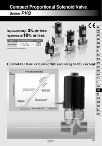
SIZE SELECTION CHART (for Steam) Applicable models: PS-12, 12C PF-12, 12C PS-15, 15C PF-15, 15C Example: Determine the size of valve meeting the following conditions: Primary pressure: 0.1MPa Secondary pressure: 0.09MPa Flow of steam (saturated): 50kg/h Differential pressure(Δ P) is: 0.1 - 0.09=0.01MPa. Identify intersection point (A) of the 0.1MPa primary pressure line and the 0.01MPa differential pressure differential curve. Draw a vertical line from point A until it intersects with the 50kg/h flow line. The intersection point is named B. Since point B is between the 15mm and 20mm size lines, the larger size, which is 20mm, is selected.
SIZE SELECTION CHART (for Water) Applicable models: PS-12, 12C, 12K, 12CK PF-12, 12C PS-15, 15C PF-15, 15C Example: Determine the size of valve meeting the following conditions: Primary pressure: 0.3MPa Secondary pressure: 0.28MPa Flow of water: 2m 3/h Differential pressure (Δ P): 0.3- 0.28=0.02MPa. Find out the intersection point A between the 0.02MPa differential pressure (ΔP) line and the 2m3/h flow line. Since point A is between the lines representing nominal diameter 15mm and 20mm, the nominal diameter should be the larger one, i.e. 20mm.
SIZE SELECTION CHART (for Air) Applicable models: PS-12, 12C, 12K, 12CK PF-12, 12C PS-15, 15C PF-15, 15C
Example: Determine the size of valve meeting the following conditions: Primary pressure: 0.1MPa Secondary pressure: 0.09MPa Flow of air (at 20℃): 50m 3/h (standard state) Differential pressure (ΔP) is: 0.1-0.09=0.01MPa. Identify intersection point (A) of the 0.1MPa primary pressure line and the 0.01MPa differential pressure curve. Draw a vertical line from 3 point A until it intersects with the 50m /h flow line. The intersection point is named B. Since point B is between the 15mm and 20mm size lines, the larger size, which is 20mm, is selected.
METHOD FOR CONNECTION OF COIL As shown in relevant specification table, different models of solenoid valve have different rated voltage. When connecting to power, make sure the voltage does not exceed the rated voltage of solenoid valve. AC200/220V
AC100/110V
W : White Y : Yellow B : Black R : Red
Connect the 4 lead wires (in different color) to power source. Power
Connect 2 lead wires to power source. Connect R and B wires, then Y and W wires, before connecting them to power source.
There are 3 lead wires on coil. Read the connection method shown on product before connecting to power source. The lead wire that left unused should be insulated using insulating tape.
Connect and then insulate Y and B wires. Connect the R and W wires to power source.
Power
ED-S, F Type DS-10, 10H, 12 Type
W : White Y : Yellow B : Black R : Red G:Grey
AC200V
AC 100V AC200V
AC 100V
REFERENCE: ABOUT EXPLOSION PREVENTION TB-03 TYPE SERIES (for indoor/outdoor, metal body, rainproof)
Terminal box specially designed for solenoid valve. Can be screwed in with lead wire of solenoid valve and protect power cable and lead wire from being exposed to rain or dust. TB-03 series are for outdoor cable and conduit.
(Without indication lamp) Rated power: 250V 15A ●TB-03 Type(standard model) With gland nut
●TB-03C Type With cap cone
●TB-03F Type With ship-class gland
(With indication lamp) Rate power: AC100V or AC200V Please specify voltage when ordering. ●TB-03L Type With indication lamp
●TB-03LC Type Lamp + cap cone
●TB-03LF Type Lamp + ship-class gland
An example of TB-03 installation
SPECIFICATIONS OF CAPCONE PLUG (TB-03C, 03LC Type)
SPECIFICATIONS OF GLAND (TB-03F, 03LF Type) Gland size
Size of applicable conduit d (mm) Hard steel conduit Flexible metal conduit
15a
9
15b
10
15c
11
16
Cut position
Applicable cable diameter(mm)
4th unit
10~12
Class 1
Class 2
3rd unit
8~10
13
10· 12
2nd unit
6~8
15
15· 17
1st unit
4~6
Fig.1 Piping example
Fig.2 Installation position Upright to horizontal pipe
SELECTION AND INSTALLATION 1. Install strainer on the primary side of solenoid valve (see Fig.1). 2. Install a bypass pipe (with stop valve) between the primary and secondary sides of solenoid valve if the operation of equipment cannot be stopped (see Fig.1). If you do not intend to install bypass pipe, install blowing stop valve, which is branched from the main pipe, right before the stop valve on the primary side of solenoid valve, to allow flushing. 3. The coil should stand upright above horizontal pipe (see Fig.1, 2).
Fig.3 Steam line application
For size 50mm (and below) valve of WS, PS series, the coil can be upright above or at the same level of (and perpendicular to) horizontal pipe. In this case, make sure the pressure differential before and after the valve is larger than 0.03MPa (see Fig.2). 4. Back flow may occur when the secondary pressure is larger than the primary pressure. To prevent back flow, install check valve on the secondary side (see Fig. 1). 5. If the valve is used for steam and the secondary pressure is negative pressure when the valve is closed, install vacuum regulating valve (vacuum breaker) on the secondary side of solenoid valve (see Fig.3). 6. Install steam trap on piping if the valve is used for steam. 7. When used for liquid, the pressure inside the piping may increase due to water hammer occurred when valve is closed or ambient temperature. In this case, it is recommended to install relief valve to protect
Fig.4 Relief valve installation
machine (see Fig.4). 2 8. Connect coil properly using 0.75mm above wire. Install fuse to protect electric circuit.
9. Repeated power-on and power-off for a long period may make the surface temperature rises up to about 70℃. Cares should be paid to avoid burning. (Depending on conditions and model, the temperature rise varies.) 10. Make sure the arrow mark on solenoid valve match with the direction of flow of fluid. 11. Leave some space for dissembling and maintenance. 12. Fix and support piping properly to prevent solenoid valve from being damaged due to weight of piping, excessively large stress, bending force, or vibration. 13. Discharge drain or apply thermal insulation if there is risk of freezing. However, the coil should not be applied with any thermal insulation.
※ Install relief valve if pressure rise due to thermal expansion or other factors is anticipated.