ISSN: 2319-8753 International Journal of Innovative Research in Science, Engineering and Technology (An ISO 3297: 2007 Certified Organization)
Vol. 3, Issue 12, December 2014
Finite Element and Experimental Investigation and Control of Vibration of Piezoelectric Smart Beam Dr. K. B. Waghulde1, Dr. Bimlesh Kumar2 Associate Professor, Department of Mechanical Engineering, J.T.M.C.O.E. Faizpur, Maharashtra, India1 Principal, Department of Mechanical Engineering, J.T.M.C.O.E. Faizpur, Maharashtra, India 2
ABSTRACT: Vibration of a smart beam is being controlled. This smart beam setup is comprised of actuators and sensors placed at the root of a simply supported beam. Vibrations can be caused by various sources including human activity and nearby motorized equipment. In this case, disturbance is produced by using a Piezoelectric actuators. The piezoelectric sensors are used to detect the vibration. Simultaneously, feedback controller sends correction information to the actuator that minimizes the vibration. To optimize results, controllers were designed using LQR control theory. This theory generally results in high-order controllers. Additionally, optimal control theory is being used to directly optimize low-order controllers. KEYWORDS: Active Vibration Control, Actuator, Sensor, Piezoelectric Material, LQR Controller. I. INTRODUCTION Active vibration control is defined as a technique in which the vibration of a structure is reduced or controlled by applying counter force to the structure that is appropriately out of phase but equal in amplitude to the original vibration. As a result two opposite force cancel each other and structure stops vibrating. Techniques like use of springs, pads, dampers, etc have been used previously to control vibration. These techniques are known as ―Passive vibration control technique‖[1]. They have limitations of versatility and can control the frequencies only within a particular rage of bandwidth hence there is a requirement for active vibration control. Active vibration control is a modern approach towards vibration control at various places; classic control techniques are becoming too big for modern machines where space is limited and regular maintenance is not possible and if possible, it’s too expensive, at such conditions AVC techniques comes handy, it is very cheap requires no manual maintenance and the life expectancy is also much more then the passive controllers. Active vibration control makes use of smart structure [2]. The system mainly requires actuators, sensors, source of power and a compensator that performs well when vibration occurs. Smart structure are used in the bridges, trusses, buildings, mechanical systems etc. analysis of a basic structure can help in improving the performance of structure under poor working conditions involving beam vibrations. The Major components are 1. Sensor patch- it is bonded to the host structure (beam). It is generally made up of piezoelectric crystals. It senses the disturbance of the beam and generates a charge which is directly proportionally to the strain. Direct piezoelectric is used. 2. Controller- the charge developed by the sensor is given to the controller, the controller lines are charged according to the suitable control gain and charge is fed to the actuator. Controller also forms the feedback functions for the system. 3. Actuator patch- the lined up charge from the controller is fed to the actuator causes pinching action (Or generates shear force) along the surface of the host which acts as a damping forces and helps in the alternating vibration motion of the beam. Converse piezoelectric is used. The beam is clamped at one end using the set table hence making it a cantilever beam, the excitation is given from the other end, the free end using an exciter, excitation of which can be controlled using a function generator (Producing a Copyright to IJIRSET
DOI: 10.15680/IJIRSET.2014.0312020 www.ijirset.com
17882
ISSN: 2319-8753 International Journal of Innovative Research in Science, Engineering and Technology (An ISO 3297: 2007 Certified Organization)
Vol. 3, Issue 12, December 2014
wave form of sinusoidal, triangle, Square) and an amplifier. The excitation produces vibrations in the beam which results in the formation of shear stress in the beam, the sensor patch present at the fixed end acts to this shear stress and produces proportional electrical signals which is fed to the computer through the D/A system and finally from the computer the signal is fed to the actuator and it produces opposite shear in the beam and the entire beam is balanced. Active vibration control finds its application in all the modern day machines, Engineering structures, automobiles, gadgets, sports equipments, ceramics, electronics etc. As it needs only a little actuation voltage hence it does not requires any external power source, the power can be directly derived from the host machine itself. As the electronics is also developing at a very fast rate hence the size of a processor is also reducing, which is very useful in the design of the control system. II. MATERIAL AND METHOD USED FOR VIBRATION ANALYSIS In this work a smart plate (aluminum plate) with one pair of piezoelectric lamination is used to study the active vibration control. The smart plate consists of rectangular aluminum beam modeled in cantilever configuration with surface bonded piezoelectric patches. The material properties are listed in Table-1. The study uses ANSYS software to derive the finite element model of the smart plate. Based on this model, the optimal sensor locations are found and actual smart beam is produced. In this experiment we have used LQR Controller to control the vibration. Figure 1 shows the line diagram for experimentation find a suitable control methodology by which we optimize the controller gain to get more effective vibration control with minimum control input. In this paper, the effect of the actuator placement on controlling the vibration of the beam and plate will be tested using numerical simulations and Experimental. The location of the sensor will be fixed throughout the simulations, where the actuator will be placed at different locations. In this paper, LQR controller will be used to study the effect of the actuator placement. We will implement the LQR controller on a piezoelectric laminate beam. The controller will be implemented such that the vibration for the closed- loop system is minimized.
Table-1 Properties of Host Structure (Al) and PZT patches
Properties Beam/Plate Young’s modulus Beam/Plate volumetric density Beam/Plate Poisson’s ratio PZT Young’s modulus PZT coupling parameter PZT impermittivity PZT volumetric density Charge constant Voltage constant Capacitance Electromechanical coupling factor
Copyright to IJIRSET
Symbol 𝑏 E/𝐶11 𝜌𝑏 ν 𝑝 Ep/𝐶11 h12 𝛽22 𝜌𝑝 d31 g31 C k31
Value 6.9x10¹⁰ 3664.67 o.3 4.20x10¹⁰ 5x10⁸ 4.55x10⁷ 7750 -3.20 x 10⁻¹⁰ -9.50 x 10⁻³ 5.50 x 10⁻⁷ 0.44
DOI: 10.15680/IJIRSET.2014.0312020 www.ijirset.com
Unit N/m2 kg/m3 ----N/m2 V/m m/F kg/m3 m/V Vm/N F -----
17883
ISSN: 2319-8753 International Journal of Innovative Research in Science, Engineering and Technology (An ISO 3297: 2007 Certified Organization)
Vol. 3, Issue 12, December 2014
Fig. 1. Experimental Setup for vibration analysis and control
III. VIBRATION ANALYSIS AND CONTROL OF PIEZOELECTRIC SMART BEAM In this case, a simple smart system containing a beam instrumented with a PZT sensor and a PZT actuator is tested for vibration control (Figure-2). The length, width and depth of the beam are taken as 0.6, 0.050 and 0.003 m, respectively. For the PZT sensor and actuator, the length, width and depth are taken as 0.015, 0.015 and 0.001 m, respectively. An LQR controller is added to the system as shown in figure-3. The output voltages of the sensor will be fed to the LQR controller then to the actuator. The actuator will be placed in five different positions, which are at 0.1, 0.2, 0.3, 0.4 and 0.5 m from the fixed end. The sensor location, as we have mentioned earlier, will be fixed throughout the simulations to ensure that we have the same output voltages fed to the actuator. Dynamic signal analyzer, DASY-Lab version-11.00 software (Data Acquisition System Laboratory) and Spectra-PLUS version 4.0.24.0 (FFT Spectral Analysis System) were used to obtain frequency responses and time responses from the piezoelectric laminate beam for experimental method. The results are compared with Finite Element Method for this ANSYS software is used to derive the finite element model of the smart beam.
Fig. 2. Smart Beam with Showing Actuator Positions
Copyright to IJIRSET
DOI: 10.15680/IJIRSET.2014.0312020 www.ijirset.com
17884
ISSN: 2319-8753 International Journal of Innovative Research in Science, Engineering and Technology (An ISO 3297: 2007 Certified Organization)
Vol. 3, Issue 12, December 2014
Fig. 3. Smart Beam with LQR Controller for Simply Supported Beam
For the system with the LQR controller, the closed-loop state equation is written as follows: Z = A − BK z + Bf f Where K is the optimum gain matrix. K = B T Sc We want to minimize the performance index defined as:
(1) (2)
∞
x T Qx + uT Ru dt
J=
3
0
Where Q and R are the state and input weight matrices respectively. So to minimize the performance index, we obtain the feedback as: u = −Kx (4) In equation-2, Sc is the solution of the controller algebraic Riccati equation AT Sc + Sc A − Sc BB T Sc + Q = 0 (5) The closed-loop eigen-values of the system, i.e. the eigen-values of the close-loop state matrix (A-BK) in Eq. (1), are computed and shown in Figure-4. The damping matrix Cuu is taken as zero matrix in numerical computations. As we can see, all the eigen-values lie in the left hand side, which means that the closed-loop system is stable. The weighting matrices for the LQR, Q and R, are 10-7 x I (2* ndof) and I (nvolt) respectively.
Fig. 4. Closed-loop Eigen-values for the Simply Supported Beam and PZT's with LQR Controller
In this case, a simple smart system containing a beam instrumented with a PZT sensor and a PZT actuator is tested for vibration control in simply supported condition is shown in Figure-3. The output voltages of the sensor will be fed to the LQR controller then to the actuator. The actuator will be placed in five different positions, which are at 0.1, 0.2, 0.3, 0.4 and 0.5 m from the fixed end. The sensor location, as we mentioned earlier, will be fixed throughout the simulations to ensure that we have the same output voltages fed to the actuator. The aluminum beam is considered as a simply supported beam. The free end has been vibrated by using an exciter. The function of the exciter is to produce under control vibration on the beam and the nature of the vibration is depend upon the input signal form the function generator. Whatever will be the nature of the waveforms, similar kind of vibration is produced in the beam. The function generator is used to generate the desired wave form which can be either of sinusoidal, triangular or Square in nature. Copyright to IJIRSET
DOI: 10.15680/IJIRSET.2014.0312020 www.ijirset.com
17885
ISSN: 2319-8753 International Journal of Innovative Research in Science, Engineering and Technology (An ISO 3297: 2007 Certified Organization)
Vol. 3, Issue 12, December 2014
Fig. 5. Closed-Loop Sensor Voltages (PZT Actuator Placed 0.1m from the Fixed End of the Simply Supported Beam) with an LQR Controller
Fig. 6. Closed-Loop Sensor Voltages (PZT Actuator Placed 0.2m from the Fixed End of the Simply Supported Beam) with an LQR Controller
Fig. 7. Closed-Loop Sensor Voltages (PZT Actuator Placed 0.3m from the Fixed End of the Simply Supported Beam) with an LQR Controller
Copyright to IJIRSET
DOI: 10.15680/IJIRSET.2014.0312020 www.ijirset.com
17886
ISSN: 2319-8753 International Journal of Innovative Research in Science, Engineering and Technology (An ISO 3297: 2007 Certified Organization)
Vol. 3, Issue 12, December 2014
Fig. 8. Closed-Loop Sensor Voltages (PZT Actuator Placed 0.4m from the Fixed End of the Simply Supported Beam) with an LQR Controller
Fig. 9. Closed-Loop Sensor Voltages (PZT Actuator Placed 0.5m from the Fixed End of the Simply Supported Beam) with an LQR Controller
The frequency range can be adjusted and set anywhere between 1Hz to 1000 KHz but as the present exciter has limitations so it can set the frequency between 1Hz to 20Khz. The frequency is high but the amplitude of the wave form is very low to produce any notable vibration in the beam. Therefore an amplifier is used to amplify the signal. The range of amplification can be varied using the knob provider at the amplifier but should not amplify more than the safe limit of the exciter. The procedure has been repeated for all other conditions for beam and plate to find out their natural frequencies. Figure-5 to 9, show the output voltages for the five different locations of the actuator. The output voltages are measured from the sensor. The output voltages are observed for the locations 0.1 m to 0.5 m (From fixed end) are 5.9 sec, 3.8 sec, 2.1 sec, 3.7 sec and 5.9 sec respectively. Figure-10 shows the frequency response without controller (open loop system). Figure-11 shows frequency response for simply supported smart beam with actuators as a Controller at five Different Positions. Figure-12 shows frequency response for simply supported smart beam with (Average) and without actuators as a Controller. The settling time for the first and last cases (at near the supports), are approximately 5.9 sec, whereas the settling time for the third case (at centre of beam), is 2.1 sec. Hence, it is better to place the actuator at centre of the beam in terms of the settling time, performs better in attenuating structural vibrations of the simply supported beam system.
Copyright to IJIRSET
DOI: 10.15680/IJIRSET.2014.0312020 www.ijirset.com
17887
ISSN: 2319-8753 International Journal of Innovative Research in Science, Engineering and Technology (An ISO 3297: 2007 Certified Organization)
Vol. 3, Issue 12, December 2014
Fig. 10. Frequency Response for Simply Supported Smart Beam without Controller
Fig. 11. Frequency Response for Simply Supported Smart Beam with Actuators as a Controller at Five Different Positions
Fig. 12 Frequency Response for Simply Supported Smart Beam with and without Actuators as a Controller (Average)
Copyright to IJIRSET
DOI: 10.15680/IJIRSET.2014.0312020 www.ijirset.com
17888
ISSN: 2319-8753 International Journal of Innovative Research in Science, Engineering and Technology (An ISO 3297: 2007 Certified Organization)
Vol. 3, Issue 12, December 2014 7
Settling Time (Sec)
6 5 4 3 2 1 0 0
0.1
0.2 0.3 0.4 Position of Actuator (m)
0.5
0.6
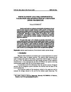
Fig. 13 Results for Simply Supported Beam
Figure-13 shows the graphical representation of settling time for respective positions of the actuators. For simply supported beam it is observed that the settling time is less at the centre of beam and is increases towards the end points of the beam. Hence for simply supported beam the vibration is controlled maximum by putting the actuator at the centre of the beam by using LQR controller. IV. CONCLUSION In this paper, a comprehensive study is done for the effect of the piezoelectric actuator placement on controlling the structural vibrations. A 2-D simply supported beam with PZT actuator and sensor are used for this study. The settling time for the first and last cases (at near the supports), are approximately 5.9 sec, for the second and fourth cases, are approximately 3.8 sec, whereas the settling time for the third case (at centre of beam), is 2.1 sec. Hence, it is better to place the actuator at centre of the beam in terms of the settling time, performs better in attenuating structural vibrations of the simply supported beam system. The simply supported beam with PZT's system showed clearly that as we place the actuator at the centre of the beam we get better results in controlling the structural vibrations in terms of the settling time. This was observed with the LQR controller. REFERENCES [1] [2] [3] [4] [5] [6] [7] [8] [9] [10] [11] [12]
Andre Preumont, A Book on ―Vibration Control of Active Structures- An Introduction‖ 3rd Edition, Solid Mechanics and its Applications, Vol. 179, Kluwer Academic Publishers, 2011. G. Songa, V. Sethib, H. N. Lic, ―Vibration Control of Civil Structures using Piezoceramic Smart Materials‖, Journal of Engineering Structures 28, pp. 1513–1524, 2006. Dunant Halim and S. O. Reza Moheimani, ―Spatial Resonant Control of Flexible Structures—Application to a Piezoelectric Laminate Beam‖, IEEE Transactions on Control Systems Technology, VOL. 9, NO. 1, pp. 37-53, 2001. J. Ducarne, O.Thomas, ―Placement and Dimension Optimization of Shunted PZT Patches for Vibration Reduction‖, Journal of Sound and Vibration, pp. 3286– 3303, 2012. K. Ramkumar, N. Ganesan and N. Shanmugam, ―Finite Element Based Active Vibration Control Studies on Laminated Composite Box Type Structures under Thermal Environment‖, International Journal of Applied Engineering Research, pp. 221-234, 2011. Tamara Nestorovic, Miroslav Trajkov, ―Active Control of Smart Structures– An Overall Approach‖, FACTA Universitatis, Series: Architecture and Civil Engineering Vol. 8, pp. 35-44, 2010. A. Benjeddou, ―Advances in Piezoelectric Finite Element Modeling of Adaptive Structural Elements: A Survey‖, Journal of Computers and Structures 76, pp. 347363, 2000. G. Songa, V. Sethib, H. N. Lic, ―Vibration Control of Civil Structures using Piezoceramic Smart Materials: A Review‖, Journal of Engineering Structures 28, pp. 1513–1524, 2006. K. Ramkumar, N. Ganesan and N. Shanmugam, ―Finite Element Based Active Vibration Control Studies on Laminated Composite Box Type Structures under Thermal Environment‖, International Journal of Applied Engineering Research, pp. 221-234, 2011. Nadav Peleg, Shimon Jiny and Moshe B. Fuchs, ―Optimal Topology Design of Piezoelectric Actuators for Vibrating Plane Structures‖, 10th AIAA/ISSMO Multidisciplinary Analysis and Optimization Conference, Albany, New York, pp. 1-9, 2004. R. Le Letty, F. Claeyssen, F. Barillot, and N. Lhermet, ―Amplified Piezoelectric Actuators for Aerospace Applications‖, AMAS Workshop on Smart Materials and Structures, Jadwisin, pp. 51-62, 2003. U. Ramos and R. Leal, ―Optimal Location of Piezoelectric Actuators‖, AMAS Workshop on Smart Materials and Structures, Jadwisin, pp. 101-110, 2003.
Copyright to IJIRSET
DOI: 10.15680/IJIRSET.2014.0312020 www.ijirset.com
17889