24 CHAPTER
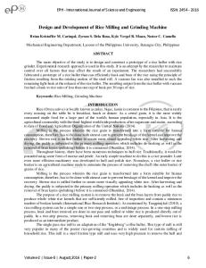
MILLING 24.1 INTRODUCTION A milling machine is a machine tool that removes metal as the work is fed against a rotating multipoint cutter. The milling cutter rotates at high speed and it removes metal at a very fast rate with the help of multiple cutting edges. One or more number of cutters can be mounted simultaneously on the arbor of milling machine. This is the reason that a milling machine finds wide application in production work. Milling machine is used for machining flat surfaces, contoured surfaces, surfaces of revolution, external and internal threads, and helical surfaces of various cross-sections. Typical components produced by a milling are given in Fig. 24.1. In many applications, due to its higher production rate and accuracy, milling machine has even replaced shapers and slotters.
Fig. 24.1 Job surfaces generated by milling machine
24.2 PRINCIPLE OF MILLING In milling machine, the metal is cut by means of a rotating cutter having multiple cutting edges. For cutting operation, the workpiece is fed against the rotary cutter. As the workpiece moves against the cutting edges of milling cutter, metal is removed in form chips of trochoid shape. Machined surface is formed in one or more passes of the work. The work to be machined is held in a vice, a rotary table, a three jaw chuck, an index head, between centers, in a special fixture or bolted to machine table. The rotatory speed of the cutting tool and the feed rate of the workpiece depend upon the type of material being machined. 447
448
Introduction to Basic Manufacturing Processes and Workshop Technology
24.3 MILLING METHODS There are two distinct methods of milling classified as follows: 1. Up-milling or conventional milling, and 2. Down milling or climb milling.
24.3.1 UP-Milling or Conventional Milling Procedure In the up-milling or conventional milling, as shown in Fig. 24.2, the metal is removed in form of small chips by a cutter rotating against the direction of travel of the workpiece. In this type of milling, the chip thickness is minimum at the start of the cut and maximum at the end of cut. As a result the cutting force also varies from zero to the maximum value per tooth movement of the milling cutter. The major disadvantages of up-milling process are the tendency of cutting force to lift the work from the fixtures and poor surface finish obtained. But being a safer process, it is commonly used method of milling.
M illin g cutter
E n d of cu t
D e pth o f cut S ta rt of cu t D irectio n of fe ed
C h ip cross-se ctio n (en la rge d)
Job
Fig. 24.2 Principal of up-milling
24.3.2 Down-Milling or Climb Milling Down milling is shown in Fig. 24.3. It is also known as climb milling. In this method, the metal is removed by a cutter rotating in the same direction of feed of the workpiece. The effect of this is that the teeth cut downward instead of upwards. Chip thickness is maximum at the start of the cut and minimum in the end. In this method, it is claimed that there is less friction involved and consequently less heat is generated on the contact surface of the cutter and workpiece. Climb milling can be used advantageously on many kinds of work to increase the number of pieces per sharpening and to produce a better finish. With climb milling, saws cut long thin slots more satisfactorily than with standard milling. Another advantage is that slightly lower power consumption is obtainable by climb milling, since there is no need to drive the table against the cutter.
M illin g cutter
S tart of cu t
D e pth o f cu t
D irectio n of fe ed Job
E n d of cu t C h ip cross-se ctio n (en la rge d)
Fig. 24.3 Principal of down-milling
Milling 449
24.4 TYPES OF MILLING CUTTERS Fig. 24.4 illustrates some types of milling cutters along with workpieces. Milling cutters are made in various forms to perform certain classes of work, and they may be classified as: (1) Plain milling cutters, (2) Side milling cutters, (3) Face milling cutter, (4) Angle milling cutters, (5) End milling cutter, (6) Fly cutter, (7) T-slot milling cutter, (8) Formed cutters, (9) Metal slitting saw, Milling cutters may have teeth on the periphery or ends only, or on both the periphery and ends. Peripheral teeth may be straight or parallel to the cutter axis, or they may be helical, sometimes referred as spiral teeth.
S h ell e n d m ill
P lain m illing cutter
E n d m ill
M etal-slittin g sa w
S ide m illin g cu tter
A n gle m illin g cu tte r
Fo rm m illin g
Fig. 24.4 Types of milling cutters
24.5 TYPES OF MILLING MACHINES Milling machine rotates the cutter mounted on the arbor of the machine and at the same time automatically feed the work in the required direction. The milling machine may be classified in several forms, but the choice of any particular machine is determined primarily by the size of the workpiece to be undertaken and operations to be performed. With the above function or requirement in mind, milling machines are made in a variety of types and sizes. According to general design, the distinctive types of milling machines are:
450
Introduction to Basic Manufacturing Processes and Workshop Technology
1. Column and knee type milling machines (a) Hand milling machine (b) Horizontal milling machine (Fig. 24.5) (c) Universal milling machine (d) Vertical milling machine (Fig. 24.6) E lectric m o to r O vera rm
Q uill S p in dle Tab le
Z X
S a dd le
C o lu m n
Y K n ee
Z
E levatin g scre w
B a se H o rizon ta l M illing M ach in e
Fig. 24.5 Horizontal column and knee type milling machine M illin g cu tter A rb or S p in dle n ose
O vera rm
Z
D u lb oa rd b ea rin g an d a rbo r sup po rt
C o lu m n X
Tab le (X -A xis) S a dd le (Z-A xis)
Z
Y
K n ee (Y -A xis)
E levatin g scre w B a se
Ve rtica l M illin g M a ch in e
Fig. 24.6 Vertical column and knee type milling machine
Milling 451
2. Planer milling machine 3. Fixed-bed type milling machine (a) Simplex milling machine. (b) Duplex milling machine. (c) Triplex milling machine. 4. Machining center machines 5. Special types of milling machines (a) Rotary table milling machine. (b) Planetary milling machine. (c) Profiling machine. (d) Duplicating machine. (e) Pantograph milling machine. (f) Continuous milling machine. (g) Drum milling machine (h) Profiling and tracer controlled milling machine Some important types of milling machines are discussed as under.
24.5.1 Column and Knee Type Milling Machine Fig. 24.7 shows a simple column and knee type milling machine. It is the most commonly used milling machine used for general shop work. In this type of milling machine the table S w ive llin g h ea d
W a ys
S p in dle M illin g cu tte r W ork Tab le
C o lu m n
S a dd le K n ee S cre w ja ck
B a se
Fig. 24.7 A column and knee type milling machine
452
Introduction to Basic Manufacturing Processes and Workshop Technology
is mounted on the knee casting which in turn is mounted on the vertical slides of the main column. The knee is vertically adjustable on the column so that the table can be moved up and down to accommodate work of various heights. The column and knee type milling machines are classified on the basis of various methods of supplying power to the table, different movements of the table and different axis of rotation of the main spindle. Column and knee type milling machine comprises of the following important parts1. Base 2. Column 3. Saddle 4. Table 5. Elevating screw 6. Knee 7. Knee elevating handle 8. Cross feed handle 9. Front brace 10. Arbor support 11. Arbor 12. Overhanging arm 13. Cutter 14. Cone pulley 15. Telescopic feed shaft. The principal parts of a column and knee type milling machine are described as under. Base It is a foundation member for all the other parts, which rest upon it. It carries the column at its one end. In some machines, the base is hollow and serves as a reservoir for cutting fluid. Column The column is the main supporting member mounted vertically on the base. It is box shaped, heavily ribbed inside and houses all the driving mechanism for the spindle and table feed. The front vertical face of the column is accurately machined and is provided with dovetail guideway for supporting the knee. Knee The knee is a rigid grey iron casting which slides up and down on the vertical ways of the column face. An elevating screw mounted on the base is used to adjust the height of the knee and it also supports the knee. The knee houses the feed mechanism of the table, and different controls to operate it. Saddle The saddle is placed on the top of the knee and it slides on guideways set exactly at 90° to the column face. The top of the saddle provides guide-ways for the table. Table The table rests on ways on the saddle and travels longitudinally. A lead screw under the table engages a nut on the saddle to move the table horizontally by hand or power. In universal machines, the table may also be swiveled horizontally. For this purpose the table is mounted on a circular base. The top of the table is accurately finished and T -slots are provided for clamping the work and other fixtures on it Overhanging arm It is mounted on the top of the column, which extends beyond the column face and serves as a bearing support for the other end of the arbor.
Milling 453
Front brace It is an extra support, which is fitted between the knee and the over-arm to ensure further rigidity to the arbor and the knee. Spindle It is situated in the upper part of the column and receives power from the motor through belts, gears. and clutches and transmit it to the arbor. Arbor It is like an extension of the machine spindle on which milling cutters are securely mounted and rotated. The arbors are made with taper shanks for proper alignment with the machine spindles having taper holes at their nose. The draw bolt is used for managing for locking the arbor with the spindle and the whole assembly. The arbor assembly consists of the following components. 1. Arbor
2. Spindle
3. Spacing collars
4. Bearing bush
5. Cutter
6. Draw bolt
7. Lock nut
8. Key block
9. Set screw
24.5.2 Planer Type Milling Machine It is a heavy duty milling machine. It resembles a planer and like a planning machine it has a cross rail capable of being raised or lowered carrying the cutters, their heads, and the saddles, all supported by rigid uprights. There may be a number of independent spindles carrying cutters on the rail as two heads on the uprights. The use of the machine is limited to production work only and is considered ultimate in metal re-moving capacity.
24.5.3 Special Type Milling Machines Milling machines of non-conventional design have been developed to suit special purposes. The features that they have in common are the spindle for rotating the cutter and provision for moving the tool or the work in different directions.
24.6 SIZE OF MILLING MACHINE The size of the column and knee type milling machine is specified by (1) The dimensions of the working surface of the table, and (2)
Its maximum length of longitudinal, cross and vertical travel of the table.
In addition to above, number of spindle speeds, number of feeds, spindle nose taper, power available, floor space required and net weight of machine will also be required for additional specification.
24.7 DEPTH OF CUT The depth of cut in milling is defined as the thickness of the material removed in one pass of the work under the cutter. Thus it is the perpendicular distance measured between the original and final surface of the workpiece, and is expressed in mm.
454
Introduction to Basic Manufacturing Processes and Workshop Technology
24.8 INDEXING AND DIVIDING HEADS Indexing is the operation of dividing the periphery of a piece of work into any number of equal parts. In cutting spur gear equal spacing of teeth on the gear blank is performed by indexing. Indexing is accomplished by using a special attachment known as dividing head or index head as shown in Fig. 24.8. The dividing heads are of three types: (1) Plain or simple dividing head, (2) Universal dividing head and (3) Optical dividing head. W orm w he el
S p in dle
In de x pin In de x cran k
In de x p la te
S e ctor a rm s
W orm
C e ntre Fa ce p la te
Fig. 24.8 Dividing head
24.8.1 Plain or Simple Dividing Head The plain dividing head comprises a cylindrical spindle housed on a frame, and a base bolted to the machine table. The index crank is connected to the tail end of the spindle directly, and the crank and the spindle rotate as one unit. The index plate is mounted on the spindle and rotates with it. The spindle may be rotated through the desired angle and then clamped by inserting the clamping lever pin into anyone of the equally spaced holes or slots cut on the periphery of the index plate. This type of dividing head is used for handling large number of workpieces, which require a very small number of divisions on the periphery. 1. Swiveling block
2. Live centre
3. Index crank
4. Index plate.
24.9 OPERATIONS PERFORMED ON MILLING MACHINE Unlike a lathe, a milling cutter does not give a continuous cut, but begins with a sliding motion between the cutter and the work. Then follows a crushing movement, and then a cutting operation by which the chip is removed. Many different kinds of operations can be performed on a milling machine but a few of the more common operations will now be explained. These are:
Plain milling or slab milling Fig. 24.9(a) illustrates the plain and slab milling operation. It is a method of producing a plain, flat, horizontal surface parallel to the axis of rotation of the cutter.
Milling 455
Face milling Fig. 24.9(b) illustrates the face milling operation. It is a method of producing a flat surface at right angles to the axis of the cutter.
Side milling Fig. 24.9(c) illustrates the side milling operation. It is the operation of production of a flat vertical surface on the side of a work-piece by using a side milling cutter.
Angular milling Fig. 24.9(d) illustrates angular milling operation. It is a method of producing a flat surface making an angle to the axis of the cutter.
Gang-milling Fig. 24.9(e) illustrates the gang milling operation. It is a method of milling by means of two or more cutters simultaneously having same or different diameters mounted on the arbor of the milling machine.
Form milling Fig. 24.9(f) illustrates the form milling operation. It is, a method of producing a surface having an irregular outline.
End milling Fig. 24.9(g) illustrates end milling operation. It is a method of milling slots, flat surfaces, and profiles by end mills.
Profile milling Fig. 24.9(h) illustrates profile milling operation. It is the operation of reproduction of an outline of a template or complex shape of a master die on a workpiece.
Saw milling Fig. 24.9(i) illustrates saw milling operation. It is a method of producing deep slots and cutting materials into the required length by slitting saws.
T-slot milling Fig. 24.9(j) illustrates T-slot milling operation.
Keyway milling Fig. 24.9(k) illustrates keyway milling operation.
Gear cutting milling Fig. 24.9(l) illustrates gear cutting milling operation.
Helical milling Fig. 24.9(m) illustrates helical milling operation.
Flute milling It is a method of grooving or cutting of flutes on drills, reamers, taps, etc,
456
Introduction to Basic Manufacturing Processes and Workshop Technology
(a ) P lan e m illin g
(b ) Fa ce m illing
(c) S ide m illing
Fo rm m illin g cutter
Job Job (d ) A n gu la r m illing
(e ) G a ng m illin g
(f) Fo rm M illin g
S a w m illing cutter
E n d m illin g cutter
(h ) P ro file m illin g
Job
(i) S a w m illing (g ) E n d m illin g 1
2
(j) T - S lot M illin g
Job
(k) K e y w a y m illing
(l) G ea r C u tting M illing
Milling 457 A
B
(m ) H e lica l m illin g
Fig. 24.9 Various types of milling operations
Straddle milling It is a method of milling two sides of a piece of work by employing two side-milling cutters at the same time.
Thread milling It is a method of milling threads on dies, screws, worms, etc. both internally and externally. As an alternative to the screw cutting in a lathe, this method is being more extensively introduced now a day in modern machine shops.
24.10 QUESTIONS 1. State the working principle of milling machine. 2. How will you classify milling machines? 3. Using neat sketch, describe the principal parts of the milling machine by neat sketches. 4. Differentiate between up milling and down milling. 5. With the help of a neat sketch explain the column and knee type milling machine and name its main parts. 6. Explain various types of milling operations using neat sketches. 7. Describe thread milling. 8. Sketch and describe the indexing head used for gear cutting. 9. Explain the principle of differential indexing. 10. What is indexing? Describe direct indexing, with example. 11. Single angle milling cutter (b) Slot milling cutter (d) Convex milling cutter. 12. How will you index the gear teeth? Sketch the indexing set-up showing necessary calculations. 13. Sketch the machining set-up indicating tool work motions. 14. Sketch and specify the milling cutter indicating important tool geometry. 15. Define the following terms used in milling operation. (a) Cutting speed (b) Feed (c) Depth of cut (d) Machining time.
458
Introduction to Basic Manufacturing Processes and Workshop Technology
25 CHAPTER
POWDER METALLURGY 25.1 INTRODUCTION Powder metallurgy is used for manufacturing products or articles from powdered metals by placing these powders in molds and are compacting the same using heavy compressive force. Typical examples of such article or products are grinding wheels, filament wire, magnets, welding rods, tungsten carbide cutting tools, self-lubricating bearings electrical contacts and turbines blades having high temperature strength. The manufacture of parts by powder metallurgy process involves the manufacture of powders, blending, compacting, profiteering, sintering and a number of secondary operations such as sizing, coining, machining, impregnation, infiltration, plating, and heat treatment. The compressed articles are then heated to temperatures much below their melting points to bind the particles together and improve their strength and other properties. Few non-metallic materials can also be added to the metallic powders to provide adequate bond or impart some the needed properties. The products made through this process are very costly on account of the high cost of metal powders as well as of the dies used. The powders of almost all metals and a large quantity of alloys, and nonmetals may be used. The application of powder metallurgy process is economically feasible only for high mass production. Parts made by powder metallurgy process exhibit properties, which cannot be produced by conventional methods. Simple shaped parts can be made to size with high precision without waste, and completely or almost ready for installation.
25.2 POWDER METALLURGY PROCESS The powder metallurgy process consists of the following basic steps: 1. Formation of metallic powders. 2. Mixing or blending of the metallic powders in required proportions. 3. Compressing and compacting the powders into desired shapes and sizes in form of articles. 4. Sintering the compacted articles in a controlled furnace atmosphere. 5. Subjecting the sintered articles to secondary processing if needed so.
458
Powder Metallurgy 459
25.2.1 Production of Metal Powders Metallic powders possessing different properties can be produced easily. The most commonly used powders are copper-base and iron-base materials. But titanium, chromium, nickel, and stainless steel metal powders are also used. In the majority of powders, the size of the particle varies from several microns to 0.5 mm. The most common particle size of powders falls into a range of 10 to 40 microns. The chemical and physical properties of metals depend upon the size and shape of the powder particles. There are various methods of manufacturing powders.The commonly used powder making processes are given as under. 1. Atomization 2. Chemical reduction 3. Electrolytic process 4. Crushing 5. Milling 6. Condensation of metal vapors 7. Hydride and carbonyl processes. The above mentioned metallic powder making techniques are discussed briefly as under. 1. Atomization In this process, the molten metal is forced through an orifice and as it emerges, a high pressure stream of gas or liquid impinges on it causing it to atomize into fine particles. The inert gas is then employed in order to improve the purity of the powder. It is used mostly for low melting point metals such as tin, zinc, lead, aluminium, cadmium etc., because of the corrosive action of the metal on the orifice (or nozzle) at high temperatures. Alloy powders are also produced by this method. 2. Chemical Reduction Process In this process, the compounds of metals such as iron oxides are reduced with CO or H2 at temperatures below the melting point of the metal in an atmosphere controlled furnace. The reduced product is then crushed and ground. Iron powder is produced in this way Fe3O4 + 4C = 3Fe + 4CO Fe3O4 + 4CO = 3Fe + 4CO2 Copper powder is also produced by the same procedure by heating copper oxide in a stream of hydrogen. Cu2 + H2 = 2Cu + H2O Powders of W, Mo, Ni and CO can easily be produced or manufactured by reduction process because it is convenient, economical and flexible technique and perhaps the largest volume of metallurgy powders is made by the process of oxide reduction. 3. Electrolytic Process Electrolysis process is quite similar to electroplating and is principally employed for the production of extremely pure, powders of copper and iron. For making copper powder, copper plates are placed as anodes in a tank of electrolyte, whereas, aluminium plates are placed in to the electrolyte to act as cathodes. High amperage produces a powdery deposit of anode metal on the cathodes. After a definite time period, the cathode plates are taken out from the