Failure Modes and Effects Analysis of Transformers
Anna Franzén and Sabina Karlsson
Royal Institute of Technology, KTH School of Electrical Engineering RCAM
Stockholm, Sweden January 2007 TRITA-EE 2007:040
Contents 1 Introduction
3
2 Reliability Centred Maintenance (RCM)
4
2.1
Failure Modes and Effects Analysis (FMEA) . . . . . . . . . . . .
5
2.2
Reliability Centered Asset Management (RCAM) . . . . . . . . .
6
3 FMEA for the transformer
7
3.1
Core . . . . . . . . . . . . . . . . . . . . . . . . . . . . . . . . . .
7
3.2
Windings . . . . . . . . . . . . . . . . . . . . . . . . . . . . . . .
8
3.3
Tank . . . . . . . . . . . . . . . . . . . . . . . . . . . . . . . . . .
8
3.4
Solid insulation . . . . . . . . . . . . . . . . . . . . . . . . . . . .
10
3.5
Cooler and oil insulation . . . . . . . . . . . . . . . . . . . . . . .
11
3.5.1
Cooler . . . . . . . . . . . . . . . . . . . . . . . . . . . . .
11
3.5.2
Oil insulation . . . . . . . . . . . . . . . . . . . . . . . . .
11
3.6
Bushings . . . . . . . . . . . . . . . . . . . . . . . . . . . . . . . .
12
3.7
Tap changer . . . . . . . . . . . . . . . . . . . . . . . . . . . . . .
14
4 Different lifetime definitions 4.1
16
Relative ageing rate . . . . . . . . . . . . . . . . . . . . . . . . .
16
4.1.1
Loss of life calculation . . . . . . . . . . . . . . . . . . . .
16
4.2
Some life time definitions . . . . . . . . . . . . . . . . . . . . . .
17
4.3
A stochastic transformer lifetime . . . . . . . . . . . . . . . . . .
17
4.3.1
18
Proposed definition . . . . . . . . . . . . . . . . . . . . . .
5 ABB Ranking
19
5.1
The method procedure . . . . . . . . . . . . . . . . . . . . . . . .
19
5.2
A method extension . . . . . . . . . . . . . . . . . . . . . . . . .
22
5.2.1
22
Model parameters . . . . . . . . . . . . . . . . . . . . . .
6 Conclusions
24
1
Introduction
This work has been made as a part of Sabina Karlsson’s master thesis and as a start on Anna Franz´en’s Ph.D. project “Lifetime modeling and management of transformers” in EKC2 at KTH. The aim was to learn about the transformer, the development of faults on it and different lifetime concepts. For the Ph.D project the aim was also to find areas where further investigation is needed. In order to learn more about the transformer and its faults and failures an FMEA analyze was done. The results of this work is given in Section 3. In Section 2 a short description of the reliability centered maintenance, RCM, method including FMEA can be found. Different life time definitions used in the literature are summarized in Section 4 and in Section 5 a description of a used ranking system for transformers is given.
3
2
Reliability Centred Maintenance (RCM)
RCM is a technique that is used to develop cost-effective maintenance plans and criteria so the operational capability of equipment is achieved, restored, or maintained. The main objective of RCM is to reduce the maintenance cost by focusing on the most important functions of the system. There are several different formulations of RCM processes in the literature. According to [1] an RCM analysis basically provides answers to the following questions 1. What are the functions and associated performance standards of the equipment in its present operating context? 2. In what ways can it fail to full fill its functions? 3. What is the cause of each functional failure? 4. What happens when each failure occurs? 5. In what way does each failure matter? 6. What can be done to prevent each failure? 7. What should be done if a suitable preventive task cannot be found? The RCM analysis may be carried out as a sequence of activities or steps. The following steps are a summarize of the main steps suggested in [2]. 1. Study preparation Define and clarify the objectives and the scope of the analysis. 2. System Selection and Definition Before a decision to perform an RCM analysis at a plant is taken, two questions should be considered. 3. Functional Failure Analysis A specific system was selected in step 2. • Identify and describe the system’s required functions and performance criteria. • Describe input interfaces required for the system to operate. • Identify the ways in which the system might fail to function. 4. Critical Item Selection The objective of this step is to identify the maintainable items that are potentially critical with respect to the functional failures identified in step 3. 5. Data Collection and Analysis Various steps of the RCM analysis require a variety of input data, like design data, operational data, and reliability data.
4
6. Failure Modes, Effects, and Criticality Analysis The objective of this step is to identify the dominant failure modes of the maintenance significant items identified in step 4. 7. Selection of Maintenance Actions For each dominant failure mode identified in step 6, decide wether a PM task or a CM task is appropriate maintenance. 8. Determination of Maintenance Intervals Determine the optimal interval of the PM task. 9. Preventive Maintenance Comparison Analysis Each PM task must meet following requirements: • It must be applicable. • It must be effective. 10. Treatment of non-Maintenance Significant Items 11. Implementation
2.1
Failure Modes and Effects Analysis (FMEA)
One of the steps in RCM is Failure Modes and Effects Analysis [2]. FMEA is a tool used to evaluate potential failure modes and their effects and causes in a systematic and structured manner. Failure modes means the ways in which something could fail. Effects analysis refers to studying the consequences of those failures. The purpose of the FMEA is to take actions to eliminate or reduce failures, starting with the highest-priority ones. The analysis can be done either in a qualitatively or quantitatively way. Basic steps in performing a FMEA could be [3]: 1. Define the system to be analyzed. Complete system definition includes defining of system boundaries, identification of internal and interface functions, expected performance, and failure definitions. 2. Identify failure modes associated with system failures. For each function, identify all the ways failure could happen. These are potential failure modes. 3. Identify potential effects of failure modes. For each failure mode, identify all the consequences on the system. ”What happens when the failure occurs?” 4. Determine and rank how serious each effect is. The most critical pieces of equipment which affected the overall function of the system need to identified and determined. 5. For each failure mode, determine all the potential root causes. 6. For each cause, identify available detection methods. 7. Identify recommended actions for each cause that can reduce the severity of each failure. 5
2.2
Reliability Centered Asset Management (RCAM)
RCM does not solve the fundamental problem of how the system reliability is impacted by component maintenance. With the aim to solve this problem a quantitative method has been developed, i.e. RCAM [4]. RCAM method relates preventive maintenance (PM) to the system reliability and total maintenance costs. The relationship between reliability and effect of maintenance outgoing from causes of failures and failure mechanism for components is denoted λ(t, P M ). The method has the following main steps: 1. Identify the critical components (system level) 2. Modeling λ(t, P M ) outgoing from causes of failures (component level) 3. Implement maintenance strategies and perform cost analysis (system level)
6
3
FMEA for the transformer
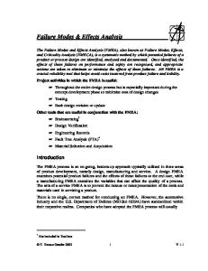
The fault trees for the transformer is a result of discussions within the RCAM group, EKC2 , discussions with experts on transformers and a literature study. In order to analyze the transformer and compose a fault tree the transformer has been divided into different subcomponents these are windings, tank, bushings, cellulose isolation and cooler and oil insulation see Figure 9. Fault trees and a short explanation for them are presented below. A fault tree for the tap changer is also given although this part is seen as steering equipment rather than a part of the transformer.
Transform er/ Transform ator Function:transform voltages form one levelto an other Funktion: transform era spänning från en nivå tillen annan
Bushings/
W indings/
Tank/
Core/
O il& Cooler/
G enom föring
Lindningar
Tank
Kärna
O lja & Kylsystem
Isolation (cellulose)/ Isolering (cellulosa)
Steering equipm ent/ Styrutrustning:
Load tap changer/ Lindningskopplare
Figure 1: Fault tree for a transformer, the transformer’s parts
3.1
Core
The core’s function is to carry magnetic flux. The failure mode of this function is a reduction of the transformer’s efficiency. The cause can be a mechanical fault in the core, due to DC-magnetism or displacement of the core steel during the construction, i.e. a construction fault [5]. Figure 2 shows a fault tree for the core.
7
Core/ Kärna Function: w ear m agnetic field Funktion: Bära m agnetiskt fällt
Failure m ode of function Loss of efficency Försäm rad verkningsgrad Failure event M echanical failure M ekaniskt fel Failure cause DC m agnetization D Cm agnetisering
Figure 2: Fault tree for core.
3.2
Windings
The windings belong to the active part of a transformer, and their function is to carry current. The windings are arranged as cylindrical shells around the core limb, where each strand is wrapped with insulation paper. Copper is today the primary choice as winding material. In addition to dielectric stresses and thermal requirements the windings have to withstand mechanical forces that may cause windings replacement. Such forces can appear during short circuits, lightnings, short circuits in the net or during a movement of the transformer [6]. A fault in the windings can occur due to material faults in the cellulose isolation, see Section 3.4 for further information.
3.3
Tank
The tank is primarily the container of the oil and a physical protection for the active part of the transformer. It also serves as support structure for accessories and control equipment. The tank has to withstand environmental stresses, such as corrosive atmosphere, high humidity and sun radiation [6]. The tank should be inspected for oil leaks, excessive corrosion, dents, and other signs of rough handling. Internal arcing in an oil-filled transformer can instantly vaporize surrounding oil which can lead to a high gas pressures that may rupture the tank [7]. In Figure 4 a fault tree for the tank is given.
8
W idings/Lindningar Function: conduct current Funktion: leda ström Failure m ode of function Short circuit Kortslutnig Failure event M echanicaldam age M ekanisk skada
Fault in insulation m aterial M aterial fel
Failure cause Construction fault Konstuktionsfel
Lightning Blixtnedslag
Transient overvoltage Transienta överspänningar
Connection of transform er Inkoppling av TRAFO
M ovem ent of transform er Flytt av TRAFO
Short circuits in the net Kortslutningsström m ar inätet
H ot spot
Ageing of cellulose Åldring av cellulosa
G enerating of copper sulfide Bildning av kopparsulfid
Low oil quality Låg oljekvalité
Figure 3: Fault tree for windings
Tank/ Tank Function: enclose oil/ protect the active part Funktion: innesluta olja / skydda den aktiva delen Failure m ode of function Leagage Läckage Failure event Tank dam age Tankskada Failure cause M echanical dam age M ekanisk skada
Careless handling/m ove Vårdslös hantering/flytt
M aterial/M ethod M aterial/M etod
Corrosion Korrosion
H igh pressure due to gas generation H ögt tryck p g a gasbildning
Inelastic gaskets O elastiska packningar
Insuficient m aintenance Bristande underhåll
Lightning/PD Ljusbåge/PD
Figure 4: Fault tree for tank
9
Aging Åldring
3.4
Solid insulation
The solid insulation in a transformer is cellulose based products such as press board and paper. Its function is to provide dielectric and mechanical isolation to the windings. Cellulose consists of long chains of glucose rings. When degradation of the cellulose occurs these chains get shorter. Degree of polymerization (DP) is the average number of these rings in the chain and indicates the condition of the paper. New paper has an average DP number of 1200-1400. A DP less than 200 means that the paper has a poor mechanical strength and may no longer withstand short circuit and other mechanical forces that appear. The solid insulation is the weakest link in the transformer insulation system, due to the degradation of the cellulose is irreversible and it is often not economically defensible to replace it. The aging of cellulose is accelerated by water, oxygen and heat [8]. An analysis of the paper can tell the moisture content and the DP number of the paper insulation. There are few available methods that maintain the paper insulation directly. One method is to dry the transformer, which reduces the water content in the insulation. Other maintenance like degasing of the oil also reduces the gas content in the paper as a new equilibrium between the gas in the oil and in the paper is reached [9]. Figure 5 shows a fault tree of the cellulose. Solid isolation/Isolering(cellulosa) Function: Insulation of the w indings Funktion: isolation av lindningarna Failure m ode of function Can not supply insulation Kan ej tillhandahålla isolation Failure event M echanical dam age M ekanisk skada
Fault in insulation m aterial M aterial fel
Failure cause M ovem ent of transform er Flytt av TRAFO
Short circuits Kortslutningsström m ar
H ot spot
Ageing of cellulose Åldring av cellulosa
Low oil quality Låg oljekvalité
Figure 5: Fault tree for cellulose isolation
10
G enerating of copper sulfide Bildning av kopparsulfid
O verload Ö verlast
3.5
Cooler and oil insulation
The functions of the cooler and oil insulation are two; cool the active part of the transformer, and be electrical insulation between the different parts [6]. In Figure 6 a fault tree of the oil is given. 3.5.1
Cooler
The cooling system can be based on either natural or forced circulation of oil and air or water. If the cooling system is based on natural circulation of oil and air, there are no pumps or fans. In the following presentation it is assumed that the oil and air or water circulation are forced by pumps. The function of the cooler is to cool the active part of the transformer. The cooler can be unable to cool due to absented cooling of the oil. This can happen due to two fault causes; either because of malfunction of the oil circulation, or because of too high temperature in the second cooling medium, air or water. The first can be caused by failure of the oil pump or by dirt and particles in the oil, that increases the viscosity of the oil. Particles can be formed in the oil due to aging. In transformers with forced oil circulation, there is a risk that the pump breaks. If the pump is unable to circulate the oil, the oil temperature inside the transformer will rise and there is a risk that the transformer will be overheated [10]. Too high temperature in the second cooling medium, is caused by bad air/water circulation due to failure of the fan or pump. High temperature outside the transformer can be the reason to high temperature of the cooling air. 3.5.2
Oil insulation
The transformer oil is a highly refined product from mineral crude oil and consists of hydrocarbon composition of which the most common are paraffin, naphthene and aromatic oils. The oil serves as both cooling medium and part of the insulation system. The quality of the oil greatly affects the insulation and cooling properties of the transformer. The major causes of oil deterioration are due to moisture and oxygen coupled with heat. Another function of the oil is to impregnate the cellulose and isolate between the different parts in the transformer. If the isolation fails there is a short circuit. A short circuit can appear if there is conducted particles present in the oil. Conducted particles are for example water, that appears in the oil as a result of the aging process of cellulose, and other particles, for example metal, these particles are also a result of aging.
11
O il/ O lja Function: Isolate and coolactive part of transform er Funktion: Isolera och kyla transform atorns aktiva del Failure m ode of function Short circuit in transf. Kortslutning itrafo.
O ver heated Ö verhettning Failure event
Conducted particles in the oil Ledande partiklar ioljan
O ilis not cooled O ljan kyls ej
Failure cause Particles in the oil Partiklar ioljan
O ver heated Ö verhettning
To hot air/w ater För varm luft/vatten
W ater in the oil Vatten ioljan
Aging Åldring
Air/w ater circulation out of function Luft/vattencirkulation fungerar ej Fan/pum p failure Fläkt/pum p fel
O ilcirculation out of function O ljecirkulation fungerar ej
D irt, particles in the oil Sm uts, partiklar i oljan Aging Åldring
Pum p failure Pum p fel
O ver heated Ö verhettning
Figure 6: Fault tree for oil insulation
3.6
Bushings
There are many sorts of bushings, and they are classified either according to isolation material on ends, or inside the bushings or to the construction. The bushings on an oil filled transformer are air-to-oil bushings, which means that the isolation material on the ends are air and on the other its oil. The isolation material inside the bushing can be oil, oil impregnated paper, resin impregnated paper or gas. Oil insulated bushings can either have an own closed oil system or share oil with the transformer. The dielectric strength of the isolation material decides the length of the bushing. There are two main constructions of bushings solid and capacitance-graded bushings. The solid bushing has a central conductor and porcelain or epoxy insulators at either end. They are use in small distribution transformers as well as in large generator step-up transformers. Capacitance-graded bushings are used for all voltage ratings above 25 kV. At predetermined radial intervals, between the conductor and the insulator, conducting layers of oil-impregnated paper or other insulation material are located [11]. The function of the bushings is to isolate electrical between tank and windings and to connect the windings to the power system outside the transformer [6]. Figure 7 shows a fault tree for the bushing. The main failure mode of the bushing is short circuit. A short circuit in the bushing can either happen due to material faults in the isolation or due to damage. A damage on bushings of porcelain can occur due to earthquakes or sabotage, like stone throwing [10]. A damage can also occur during handling, 12
shipping or due to flying parts from other failed equipment [11]. A material fault in the isolation can occur due to water or dirt. Damages, cracks in the porcelain and bad gaskets can give water an entrance to the oil isolation in the bushing [10]. It is important that the gasket between the transformer tank and the bushing are absolutely tight so that no air or water are allowed to enter the transformer. As the gasket ages it becomes inelastic and allows water and air to enter [10]. Both water and dirt in the bushings is a consequence of insufficient maintenance. Periodic inspections and maintenance are made on bushings in order to find potential problems. It is important that the oil level remains on a normal level. If the oil level decrease it is a sign of a leak in the bushing. If the oil level sinks and exposure the paper isolated parts it can lead to a dielectric failure in the bushing. If the leak is on the air side it can give water an entrance to the bushing [11]. If the transformer is situated in a highly polluted environment the bushings shall be washed regularly [11].
Bushings/ G enom föring Function: connect w indings w ith net, isolate betw een tank and w indings Funktion: föra ström till/från lindningarna, isolera m ellan tank och lindningar Failure m ode of function Short circuit Kortslutning Failure event Fault in isolation m aterial Feliisolationen, m aterialfel
D am age on bushings Skada på genom föraren
Failure cause
D irt Sm uts
Lack of m aintenance Bristande underhåll
W ater penetration Vatteninträngning
Sabotage, stone throw ing Sabotage, stenkastning
Inelastic gaskets O elastiska packningar Aging Åldring
Figure 7: Fault tree for bushings.
13
Careless handling Vårdslös hantering
3.7
Tap changer
The function of a on-load tap-changer (OLTC) is to regulate the voltage level by adding or subtracting turns from the transformer windings. The OLTC is built in two separate sections; the diverter switch and the tap selector (figure 8). Due to the fact an interrupting of the supply is unacceptable for a power transformer, these are fitted with an complex mechanism that change turns ratio without interrupting the load current. To obtain a non interrupted flow current the tap change procedure is performed in two steps [11]. 1. The next tap is preselected by the tap selector at no load 2. The diverter switch transfers the load current from preselected tap. The tap selector makes the new tap connection before releasing the old, and avoids the high current from the short-circuited turns by temporarily placing a large diverter resistor in series with the short-circuited turns before breaking the original tap connection. To avoid contamination of the transformer oil, the diverter switch has it’s own oil filled housing separate from the rest of the transformer. An annual inspection should be carried out to read the counting device that count number of operations performed by the diverter switch. These readings are used to determine when an overhaul should be performed. The oil in the diverter switch housing has to be cleaned with certain intervals. The only parts that should require maintenance during the service life according to [12] are the diverter switch contacts that may need to be replaced, and the Motor-Drive Mechanism which provides the drive to allow the OLTC to operate.
Figure 8: Switching principle Source:[11]
14
Tap selector/Lastskopplare
D iverter sw itch/
Function: Regulate the voltage level
O m kopplarekopplare
Funktion: Variera/ändra spänningsnivån
Function: M aintain a coherent current Funktion: Bibehålla en jäm n ström
Failure m ode of function Can not change voltage level Kan ej byta spänningsnivå
M echanical dam age M ekanisk skada
Short circuit Kortslutning
Failure event
Contact failure Felikontakt
Failure cause Contam ination of oil Partiklar ioljan, koxning
W ear Slitage
Im proper use Felanvändning
Lack of m aintenance Bristande underhåll
Figure 9: Fault tree for the tap selector and the diverter switch.
15
4
Different lifetime definitions
In the literature and when discussing with different people different lifetime definitions are used, some of them are mentioned here. First the definition of relative aging rate and loss of life in the cellulose is described according to the IEC standard. Then some life time definitions used in other literature is given and at the end a proposed life time model is described.
4.1
Relative ageing rate
In the IEC standard [13] a method to calculate the relative ageing rate of the cellulose isolation, depending on the hot-spot temperature, is given. This ageing rate is then used to evaluate the isolations loss of life. The model presented in [13] is only based on the insulation temperature as the controlling parameter. The relative ageing rate V =1,0 corresponds to a temperature of 98 o C for non-thermally upgraded paper and to 110 o C for thermally up-graded paper. Since the temperature distribution is not uniform , the part that is operating at the highest temperature will undergo the greatest deterioration. Therefor, the rate of ageing is referred to the winding hot-spot temperature. The relative aging rate for non-thermally upgraded paper is defined according to following equation Vn = 2(θh −98)/6
(1)
and for thermally upgraded paper Vn = e
15000 ( 110+273 − θ15000 +273 ) h
(2)
where θh is the hot-spot temperature in o C. 4.1.1
Loss of life calculation
The model for the loss of life can also be found in [13]. The loss of life L over a certain period of time is defined as following Z t2 L= Vn dt (3) t1
where • Vn is the relative ageing during interval n according to 1 and 2 • tn is the nth time interval • n is the number of each time interval • N is the total number of intervals during the period considered
16
4.2
Some life time definitions
Economical life time Economical lifetime is a theoretic concept, and refers to the time up to the replacement time which gives the optimal profit from an alternative investment [14]. Technical lifetime The technical lifetime for a component is defined as the time until the component is unable to perform the desired function and it is impossible to repair the component [15]. Strategic lifetime When the strategic lifetime of the transformer is at the end, it is replaced because of changes in the power system. The old transformer is not able to transform between the wanted voltage levels, either because it is not designed for these voltage levels and currents or the power supplier wants a safer transformer in that place [16]. Equivalent lifetime Different transformers are situated on different places in the power system and naturally they are exposed to different stresses like for example short circuits. Therefore, in order to compare different transformers with each other it can be useful to define an equivalent lifetime. In the report ”Livsl¨angdsdefinitioner f¨or krafttransformatorer” Elforsk defined the equivalent lifetime as: X X Le = ˚ A+ LK + LM where ˚ A is the transformers age, LK are the stresses from lifetime consuming factors and LM are the stresses from lifetime intensifying factors. The LK:s are positive but the LM :s are negative numbers [15].
4.3
A stochastic transformer lifetime
The life time of an equipment is stochastic. When working with maintenance there is a need to connect the equipment’s life time with the maintenance actions performed on it. Among the life time definitions above there is only one, the definition of equivalent life time that takes maintenance and failures into account. However that definition uses the age of the transformer to day and values on stresses from life time consuming and intensifying factors, ie. it’s not stochastic. Here a definition of a stochastic life time that takes the stochastic influences of maintenance and failures into consideration is proposed. 17
4.3.1
Proposed definition
The lif etime, T , of the transformer is a stochastic variable, i.e. a stochastic function that depends on a couple of stochastic variables with different distributions. n m X X T (X, Y, Z) = X − Yi + Zj i=1
j=1
Where X is the lifetime according to the design of the transformer measured from the moment when the transformer is put into operation until it is shutdown. Y is a stochastic vector with n elements, each one corresponding to the impact of one “fault” type on the lifetime. Z is a stochastic vector with m elements, each one corresponding to the impact of a maintenance action on the lifetime. It is possible that some of the Y ’s depend on time or for example the magnitude of a short circuit current. Y can for example depend on the time until the fault is discovered or the time until maintenance is done to correct the fault.
18
5
ABB Ranking
In [17] and [18] a condition-based evaluation method to assess the lifetime status of power equipment is represented. The method is developed by ABB and is a unit oriented approach that concentrates on the serviceability for use of a individual unit. The objective of this method is to identify the most vulnerable units in a population by ranking them on the basis of certain aspects. This ranking is then basic-data for decision-making regarding to take appropriate actions on the highest priority units, i.e. the most critical ones in the population. These activities could be either suitable maintenance activities or other adequate measures such as replacement or refurbishment. Some results from a case study done on eight GSU transformers applying this method are also represented in [17]. The following description of the method is considering transformers.
5.1
The method procedure
The method procedure could be divided in following 5 steps. 1. Identify a set of evaluation criteria. 2. Collect data. 3. Design inference net by formulate rules and relations. 4. Determine the evaluation criterion value. 5. Rank the units.
1. Identify a set of evaluation criteria The first most important question to ask is on what the evaluation shall be based on. To answer this question one has to identify the different aspects (or risks) that could jeopardize the functionality or suitability for use of a unit in the population under consideration. Exactly which aspects that should be involved depend on the type of transformer, location, load etc. From the case-study on a population of transformers in [17] following aspects were further investigated:
Thermal aspects • Brittleness of aged paper • General ageing of insulation (including oil) • Possible heating of core bandages Electrical aspects • General view based on influential 19
• Factors including design, ageing and sign Mechanical aspects • Tilting (axial forces) • Buckling (radial forces) Loadability • Short time emergency loading • Long time emergency loading The aspects that one wants to assess are denoted evaluation criteria. The most important aspects for the evaluation have to be identified, and these will then constitute the set of evaluation criteria.
2. Collect data Enough and relevant in data for each evaluation criterion is necessary. The input data could come from different sources: • Design and manufacturing • Normal operation and environmental conditions • Exceptional lifetime events in the power system • Unit maintenance, relocation, repairs, etc • Monitoring and diagnostics • Oral information from experts in the field
3. Designing the inference net by formulate rules and relations This step aims to develop evaluation procedures that shall determine a value for each evaluation criterion. These procedures can be seen as knowledge-based inference nets that describe causalities and influence factors. The input is unit data related to a certain aspect, and the output is an evaluation criterion value for the unit. The inference net consists of rules and relations that describe the dependencies between different input data for each evaluation criteria. The net could be a combination of different formulated rules, such as conventional formulas,weighting procedures or logical connections. The inference should be designed so that the resulting evaluation criteria value is a relative measure of the technical risk. To determine which rules each evaluation criteria are required, it is necessary to first describe the model dependencies and relationships between the known information. The rules in the inference net for the case study in [18] are defined by transformer experts and the evaluation procedure is data driven. 20
4. Determine the evaluation criterion value The evaluation criterion value for each unit is determined by using the inference nets developed in step 3.
5. Rank the units Perform partial ranking by ranking the units with the respect to one evaluation criterion at time outgoing from the values from step 4. Table 1 is the resulting partial ranking list from the case study in [18]. The lower ranking number the worse case the unit represents within the population. In cases there it was impossible to significantly discriminate the units they were given the same ranking number. Table 1: Ranking numbers for 8 transformers in the case study [17]. The lower ranking number the worse case within the population. Abbreviations of the tested aspects:aF=axial force rF=radial force bp=brittlepaper co=thermal heating of core gia=general insulation ageing el=electric aspects Units aF rF bp co gia el TRAFO 1 6 6 1 1 1 3 TRAFO 2 7 6 3 4 2 4 TRAFO 3 7 6 3 4 2 4 TRAFO 4 1 1 2 6 5 7 TRAFO 5 1 1 7 6 6 6 TRAFO 6 1 1 3 2 2 5 TRAFO 7 4 1 6 2 6 8 TRAFO 8 4 1 8 6 2 2 As can be seen in Table 1, various evaluations criteria can rank the transformer in different order. Hence, a ranking number for one aspect is not directly comparable to ranking number for another aspect. To perform a overall ranking, i.e. a ranking list that takes more than one aspect in consideration, the user of the equipment must decide which type of aspect to emphasize and if some weighting procedure should be used. Sometimes it may be more appropriate to perform a ranking which just involves some of the determined aspects. For example a ranking list with respect to thermally aspects outgoing from Table 1 should be performed based on the partial ranking lists of bp, co and gia. Table 1 is used to illustrate a constructed example how an overall ranking list could be performed. Each aspect i is assigned a weight wi based on the relative importance to the overall transformer condition. We denote the calculated partial ranking number for aspect i and unit j as aij . Here, just for illustration purpose, we emphasize the thermally aspects in a weighting procedure by assigning wi = 10 to the aspects bp, co and gia (i = 3, 4 and 5) and wi = 1 to the others aspects (i = 1, 2 and 6). In other words, this overall ranking is derived under the assumptions that the thermally aspects are ten times more critical then the other three aspects.
21
Then we calculate aorank,j for the 8 units according to equation 4. P6 aorank,j =
i=1 P 6
wi aij
i=1
wi
f or j = 1, ..., 8
(4)
The result of the overall ranking calculations is represented in Table 2. The aorank,j column is the rounded values from the calculations and can be seen as the relative technical risk measure under the assumptions that the ranking numbers in Table 1 is scaled in that way. The Ranking column shows in which order actions should be taken within the population. Table 2: Results of overall ranking example of the 8 transformers in Table 1. Unit aorank,j Ranking TRAFO 1 1 1 TRAFO 2 3 3 TRAFO 3 3 3 TRAFO 4 4 4 TRAFO 5 6 7 TRAFO 6 2 2 TRAFO 7 5 5 TRAFO 8 5 6
5.2
A method extension
Often not all of the transformers in a population are equally critical. A failure by some transformer can cause more consequential damage than others. An extension of the the above described method is represented in [19], there also the strategic or economic importance of the units to the user is considered. 5.2.1
Model parameters
In the extended model we have 2 parameters: 1. Technical risk 2. Importance The technical risk is the result from the step 1-5, i.e. the ranking list. Importance is cost consequences in a broad sense. Apart from economical losses the importance parameter could for example also include potential risk consequences a unit failure brings. The goal is to scale the units in the population in terms of ascending importance. To derive this importance scale the population must be investigate and it is up to the transformer owner to decide what the importance parameter should include.
22
Risk index and interpretation of Technical Risk and Importance graph To obtain the risk index value one has to plot each unit in a Technical Risk and Importance diagram. Scale the the technical risk of each unit on a low-to-high scale, for example 0-10. Then also order the strategic or economic importance of each unit on a scale, for example 1 to 10. The closer an unit falls the ”high priority area” the higher risk index value it will be assigned. Hence, units at the same distance from the ”high priority area” have the same risk index value. The higher risk index value a unit has, the higher priority regarding to investments for maintenance, replacements etc. To illustrate an example we using the results from the aovrank,j column in Table 2. Assuming that the results is appropriate scaled in a technical risk sense we scale the technical risk for these 8 units on a low-to-high 1-8 scale. Thus we need to ”switch” the numbers in the aovrank,j column to obtain this. After investigation of the population we conclude that it is appropriate to use a 1-10 scale for the importance and further that the units 1-2 have a low importance (importance=1), 3-6 medium importance (importance=5) and 9-10 have a high importance (importance=9). Figure 10 shows the results in a Technical Risk and Importance graph. Technical risk and Importance diagram 8
1
7
6
Technical risk
6
3
2
5
4
4 3 2 1 0
0
High priority Medium priority Low priority TRAFO 1 TRAFO 2 TRAFO 3 TRAFO 4 TRAFO 5 TRAFO 6 TRAFO 7 2 4 TRAFO 8
7,8 5
6
8
10
Importance
Figure 10: Combined equipment assessment considering total technical risk and importance aspects. The shorter distance the unit falls to the high priority area, the higher risk index it will be assigned. According to the risk index method unit 6,7 and 8 have the highest priority within the population. Note for example that the unit 1, that has the highest priority according to the overall ranking list (Table 2), is here assigned a lower priority due to the low importance within the population.
23
6
Conclusions
The ABB ranking method gives a relative ranking within the investigated population. The results from different populations are not comparable. A method with population independent results would be better. A life time distribution based on statistics, according to the proposed definition in Section 4.3.1, can be used to compare different transformers. That definition also takes maintenance and failure events into consideration. Further investigation of the fault trees could give valuable information about the included stochastic variables.
24
References [1] John Moubray. Reliablity-centred Maintenance. Butterworth-Heinemann, 1991. [2] Arnljot Høyland Marvin Rausand. System Reliability Theory, Models, Statistical Methods and Applications. Jhon Wiley and Sons, second edition, 2004. [3] Wikipedia. 2006.
Fmea.
Internet page http://de.wikipedia.org/wiki/FMEA,
[4] R. Eriksson L. Bertling, R. Allan. A reliability-centered asset maintenance method for assessing the impact of maintenance in power distribution systems. IEEE Transactions on power delivery, 20(1), January 2005. [5] Oral discussion Ph.D. Student, David Ribbenfj¨ard KTH. 2006. A. Carlson. Power transformer design fundamentals. Technical report, [6] ˚ ABB Transformers, 2000. [7] Hydroelectric research and technical services group D-8450. TRANSFORMER MAINTENANCE FIST 3-30. United States Department of the Interior Bureau of Reclamation, Denver, Colorado, October 2000. [8] Rashmi Sanghi. Chemistry behind the life of a transformer. Resonance, pages 17–23, June 2003. [9] D. Linhjell T. J. Painter L. E. Lundgaard, W. Hansen. Aging of oilimpregnated paper in power transformers. IEEE transactions on power delivery, 19(1), January 2004. [10] ABB. Transformer Handbook. Z¨ urich, 2004. [11] James H. Harlow, editor. Electric power transformer engineering. 2004. [12] ABB Components. On-Load Tap-Changer Type UC, Technical Guide, 3 edition, Mars 1996. [13] IEC Standards 60076-7. Power transformer - Loading guide for oilimmersed power transformer, first edition, December 2005. [14] Jan Storesund. V¨armeforsk.
Handbok f¨ or livsl¨ angdsarbete f¨ or energianl¨ aggningar.
[15] A. Gabrielsson. Livsl¨angdsf¨ordelningar f¨or krafttransformatorer. till¨ampning av bayesiansk metodik. Technical Report 06:46, Elforsk, June 2006. [16] Oral discussion Lars Pettersson. ABB Transformer, 2006. [17] U. Sundermann L. Petersson, N.L Fantana. Life assessment: Ranking of power transformer using condition based evaluation, a new approach. CIGRE Paris Conference Paper 12-204, 1998.
25
[18] J.O. Persson K.I. Walld´en L. Petersson, N .L Fantana. Condition based evaluation of net transformers - experience from a new ranking procedure. CIGRE Paris Conference Paper 12-108, 2002. [19] L. Petersson N.L Fantana. Condition-based evaluation, a new platform for power equipment life management. ABB review. The corporate technical journal of the ABB group, (4):45–54, 2000.
26