Proceedings: Indoor Air 2002
FAILURE MODES AND EFFECTS ANALYSIS (FMEA) USED ON MOISTURE PROBLEMS A Nielsen∗ Energy Technology, SP - Swedish National Testing and Research Institute, Borås, Sweden ABSTRACT Preventing “damp” buildings will give a better indoor climate and less risk of health problems for the inhabitants. Many industries use FMEA (failure modes and effect analysis) to reduce the risk. This method is new in the building sector. Part of an analysis of a building and the installations is presented. The failure mode table gives the possible failure modes from free water. Based on the failure modes can the effects for each failure be found and prevention measures can be taken. Some modes are easy to see others are hidden and will first be seen if something else fails. In the future it should be possible to calculate the risk levels and compare different solutions. The FMEA analysis can be used in planning and building of new houses, but also as help in preventing failures in existing buildings. INDEX TERMS Moisture, Failure modes, Maintenance, Technical installations, Building construction INTRODUCTION “Dampness” in buildings gives a higher risk for health problems (Bornehaug et al., 2001), than dry buildings. It is therefore important to reduce the risk of moisture damage in buildings. As we do not know the coupling between moisture and health we must regard excess moisture as a problem. The traditional method for solving moisture failures is to fix it, when found. We need a more systematic method to avoid future moisture failures. Solving similar failure problems is important in many types of stationary industry (Moubray, 1999) (O'Connor, 1995) as production of aircrafts, cars and computers. The producers want to prevent failures by analysing the systems before production and having a feedback from accidents. This is done in the airline industry, where every accident is analysed to find the causes. After each accident a number of changes in the design or in the maintenance is suggested. Finding failure modes and analysing the effects of the failures can also be used in the building sector. FAILURE MODE AND EFFECT ANALYSIS (FMEA) Failure mode and effect analysis (FMEA) is described in (US MIL STD 1629, 1980). It is intended to recognize and evaluate the potential failures of a product (the house) or process (construction) and find effects of failures. It will identify actions that can be taken to prevent failures by elimination or reducing the chance of occurrence. The concept of FMEA is not new. Designers have always thought of failure modes and how to prevent them. The FMEA method is new in the building sector and gives a more systematic approach. The building sector has many rules and guides for building without problems. The building sector is different from most stationary industry as only part of the building process is industrialized. Many operations are not repeated and the work is adjusted on site. The workmanship is therefore important for the result. Both human and technical errors must be included in the ∗
Contact author email:
[email protected]
38
Proceedings: Indoor Air 2002
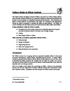
analysis. The FMEA will typically begin with making one or more block diagrams. The purpose is to understand the logic in the system. Building Room
Installation
Roof
Walls
Floor
Space
Water system
Heating system
Sprinkler
Solar heating
Climate Rain and snow
Ground water
Flooding
Internal moisture
Temperature
Figure 1. The building as a system The diagram (figure 1) views the building as a system. It is divided in three parts: the room, the installation and the climate. The room is divided in the different structural parts and the space (humid air). The installations are divided in water system for cold and warm water and the heating system, if it is water based. The climate includes the effect of rain and snow, flooding and ground water and internal moisture sources. The three main parts can each be subdivided as for instance the water installation in figure 2. Water installation
Pipes
Metal Plastic
Equipment
Taps
WC
Hand-wash basin
Bath
Pump
Washing machine
Tank
Dish-washer
Water heater
Showers
Fittings/Joints
Bend Joints
Figure 2. Water installation On the top level we divide the installation in pipes, fittings, taps and equipment. Pipes are single length pipes without joints. All joints between pipes and between pipes and fittings or equipment are one group, as these are weak points with a higher risk. Taps are points with high risk if the tap is left open. The equipment consists of all types of water-connected equipment. Analysing a water installation as a separate system can be done in a FMEA analysis similar to many industry process systems. But the analysis cannot be done without including the building, as a leakage will have different consequences depending on where it occurs. The water can run down the drain without damage in rooms with drain. The repair cost will be low. In rooms without drain as living rooms or worse in hidden spaces will a leakage give a more extensive damage and the repair cost can by high, if leakage is not found and stopped. FAILURE TYPES Potential failure modes in industry are modes where the system fails totally or not being able to output the expected amount or quality. Moisture failures in buildings will include excess moisture that could give health problems (Bornehaug et al., 2001). As we do not know the
39
Proceedings: Indoor Air 2002
coupling between moisture and health, we must regard too high moisture content as a failure. Main failure modes are: • • •
Liquid water in the building – example leakage from water installations Surface condensation - example bathrooms after bathing Internal condensation in the structure – example roof without vapour barrier
Table 1 is part of a failure mode table for moisture problems in buildings. The first (top) level failure modes come from free water in the buildings. The second level of failure modes is divided in water from the roof or the drainage system. The failure modes are further divided Table 1. Failure modes from liquid water in the building (level 1). Level 2 Level 3 Level 4 Leakage rain water Leakage from roofs Leakage in roofing material
Level 5 Mechanical damage Montage error Aging of material
Leakage from skylights Leakage from roofing Montage error felt joints Mechanical damage Aging of material Leakage from gutters Leakage from joint to walls Leakage from joints Montage error with pipes, cables and Design error duct going through the Cracking from roof movements Leakage from drain system
Leakage from pipes
Leakage from pipe material
Leakage from joints between pipes Leakage from fitting Montage error Leakage from drains in Montage error floors Filled with solid waste Leakage from Leakage trough watertight floors (ex. material bathrooms) Leakage trough joints Leakage joints with walls Leakage joint with pipes, cables and ducts
40
Mechanical damage Corrosion Too high temperatures Constant water pressure Montage error
Proceedings: Indoor Air 2002
down to fifth level. The table is based on (Andersson and Kling, 2000), (Nevander and Elmarson, 1994), (Nielsen, 2000) and (Norwegian Building Research Institute, 2001). It is often thought that we can find “root causes” in the FMEA analysis. It implies that we can find a final and absolute level of causation. This is very seldom the case. We will generally be able to go in still more in detail with the causes. FAILURE EFFECTS The next step is to find the failure effects. Failure effects describe, “What happens” when a failure mode occurs. It is not the same as a failure consequence as “Does it matter”. The failure effect description shall state if obvious physical effects accompany the failure as unusual smell, visible moist spots or pools of water on the floor. Table 4 is a table with description of failure effects for some of the failure modes from table 3. The same failure effect can have different causes as finding liquid water in the form of dripping or water flow. This could come from leakage in the water or drainage system, leakage in the heating system and drips from condensation on the surface or in the construction. In some cases is the source obvious as a leakage from a dishwasher. After making a list of failure effects it is possible to write prevention methods for each failure as it is done in the table. This could for instance be to make tests of the system and check of the workmanship quality. Some function failures are seen rather easily as flooding from a leakage in the water installation. Or it could be seen or heard as dripping of water from the system. Other cases give a bad smell from mould in the structure or on a surface. These are examples of evident function failures. Other type is hidden failures, that is not seen and that will first be evident in combinations with other failures. Finding sources for hidden failures are difficult without using drawings and/or opening of the construction. An example of a hidden failure is a missing closing valve in the water installation or that the valve cannot be closed. This failure will first be found when you need to stop a water leakage. A similar example in the industry is a stand-by pump. A failure in that pump will only affect the system, when the normal pump fails. Many moisture problems are caused by hidden failures. They will first be evident when another failure also happens. Typical hidden moisture failures are modes that can give condensation or high humidity inside a construction. The FMEA analysis can be expanded with a risk evaluation calculating the probability for loss of function, but this is difficult for buildings, as there is no systematic collection of data on the failure risks in constructions or installations. Calculation of risk can sometimes be done as for condensation in a wall (Nielsen, 1995). But in most cases have we no numerical data. But we know from practice, that certain solutions are more risky as placing a water tap in a room without drain. The maintenance people in the building sector know much of where we have the risk. Their information must be part of the analysis. The FMEA analysis can be done for new buildings during the planning and building phase to reduce and eliminate important risk points. An example is: After making the drawing of the water installation we can find the points with the high risk as joints and taps. Are these points in rooms with a drain? Move these points if possible or make extra control of the workmanship. The analysis for existing buildings can find risk points that must be supervised or eliminated. Removing risk points can be done with rebuilding and/or in the normal maintenance of the building. CONCLUSIONS FMEA analysis on buildings is a new method for getting better quality of the buildings, as the analysis combines results from research and practise. The analysis is a good help in finding better solutions for moisture proof buildings. Using this systematic approach gives better
41
Proceedings: Indoor Air 2002
Table 2. Failure modes, failure effects and prevention methods for leakage in roofs. Failure modes Failure effect Prevention method Leakage in Mechanical Seen as dripping or water flow No normal traffic on the damage in the building during and after roofing material. Remove all roofing rain. Location of damage can waste material on roofs. Inspect material roof. be very difficult. Control system for Montage error The roof leaks shortly after construction. Seen as dripping workmanship. The contactor or water flow in the building must repair the damage. during and after rain. Location of damage can be very difficult. Aging of The material cracks from frost Use materials tested for aging in a climate as on site. Inspect material damage or temperature roof and look for cracks or variation. other damages Use skylights that have been Leakage from Seen as dripping or water skylights flowing in the building at the tested for water tightness. Have skylights during and after rain. control system for workmanship. Control system for Leakage from Montage error The roof leaks shortly after construction. Seen as dripping workmanship. The contactor roofing felt or water flow in the building must repair the damage. joints during and after rain. Location of damage can be very difficult. Mechanical See mechanical damage on damage roofs Aging joints See aging of roof materials Leakage from Water damage on facade from Control gutters for leakage. In gutters gutter leakage. Possible water case of repeated leakage should gutters be repaired. damage into constructions. Roofing material should Leakage from The roof leaks. Seen as joint to walls dripping or water flow in the continue approx 10 cm up building during and after rain. connecting walls. Rain should not be able to come under the Location of damage can be roof material at the joint. very difficult. Montage of signboards or Leakage from Montage error The roof leaks shortly after construction. Seen as dripping ventilation equipment on the joints with or water flow in the building roof must be specially checked pipes, cables during and after rain. Location to ensure watertight solutions and duct in of damage can be very difficult. the roof Design error As above Areas around pipes, cables and duct must be planned, so it is easy to make watertight solutions. As above Look for cracking around Cracking pipes, cables and ducts. from Damage must be repaired movements
42
Proceedings: Indoor Air 2002
understanding of building failures, their effects and remediation methods. Finding and preventing hidden failures is a very important task. Using the right solution in the constructions and installations can reduce the risk of serious damage from water leakage. The analysis on actual buildings is important in the planning and building phase and must include the influence of the user. The analysis is a very useful tool in planning of repairs in facility management (FM). The analysis can produce checklists and information on critical points in the actual building structured for the different parties in the building process as architects, engineers and craftsmen. Selecting, building and keeping moisture-proof constructions are important for preventing future health problems for the building inhabitants. ACKNOWLEDGEMENTS The work is supported by FORMAS - the Swedish Research Council for Environment, Agricultural Sciences and Spatial Planning and the International Centre for Indoor Environment and Energy at the Technical University of Denmark REFERENCES Andersson J and Kling R 2000: Bygg Vattenskadesäkert – VASKA viser vägen, (Build waterproof – VASKA project) Swedish Building Research Council, Sweden, report T3 2000 Bornehaug C G, Blomquist G, Gyntelberg F, et al. 2001: Dampness in Buildings and Health. Nordic Interdisciplinary Review of the Scientific Evidence on Associations between Exposure to ”Dampness” in Buildings and Health Effects (NORDDAMP), Indoor Air, vol. 11, no 2, page 72-86 Moubray J 1999: Reliability-centered Maintenance, 2.edition, Butterworth-Heinemann, Oxford, UK, ISBN 0 7506 3358 1 Nevander L E, and Elmarson B 1994: Fukthandbok (Moisture Handbook), 2nd edition, Svensk Byggtjänst, Stockholm, Sweden Nielsen A 1995: Use of statistics for prediction of condensation in a wall construction. International symposium Indoor Air Quality in Practice, Moisture and Cold Climate Solutions, ISIAQ, Oslo, Norway, 19-21 June 1995, page 206-216 Nielsen A 2000: Analysis of the moisture problems in bathrooms, Healthy Buildings 2000, Helsinki, Finland, August 5-10, vol. 3, page 495-500 Norwegian Building Research Institute 2001, Building Detail Sheets, Oslo, Norway, new update every year O'Connor P D T 1995: Practical Reliability Engineering, Third edition Revised, John Wiley & Sons, Chichester, UK, ISBN 0-471-96025-X US MIL STD 1629 1980: Procedure for performing a Failure Mode, Effects and Criticality Analysis, method 102, 24 November 1980
43