Extended Overview Techniques for Outdoor Augmented Reality Eduardo Veas, Raphaël Grasset, Ernst Kruijff, and Dieter Schmalstieg
Fig. 1. (Left) In multi-view AR, tapping on the green camera icons switches to their associated view, providing a zoom-in to remote areas of a site. (Right) The variable perspective view deforms the datasets to overview the site. Abstract—In this paper, we explore techniques that aim to improve site understanding for outdoor Augmented Reality (AR) applications. While the first person perspective in AR is a direct way of filtering and zooming on a portion of the data set, it severely narrows overview of the situation, particularly over large areas. We present two interactive techniques to overcome this problem: multi-view AR and variable perspective view. We describe in details the conceptual, visualization and interaction aspects of these techniques and their evaluation through a comparative user study. The results we have obtained strengthen the validity of our approach and the applicability of our methods to a large range of application domains. Index Terms—Information Interfaces and Presentation, mobile augmented reality, multi-perspective views, situation awareness, navigation.
1
I N TR O DU C TIO N
The tremendous increase of information available nowadays has triggered the need for more efficient and usable visualization techniques. In scientific areas such as environmental sciences, a demand has also been growing regarding accessibility of information in the field. Dedicated mobile computing techniques have therefore been proposed for visualizing datasets related to the scientist’s physical location (aka in-situ visualization). For instance, mobile Augmented Reality (AR) visualization offers a practical solution when datasets need to be presented in a real life context, merging digital content with the real world. Visualizing abstract data, such as wind sensor measurements or hydrology simulations, by overlaying them on real landscape in a spatially coherent way provides an intuitive tool to analyze and understand the data. Nevertheless, due to its situated nature, AR has limiting factors that affect spatial awareness. In the course of a recent environmental visualization project, we observed that the solely ego-centred view delivered by mobile AR is not sufficient for an environmental scientist to perform her regular activities. The first person view of AR situates the user within the dataset, but having access to other viewpoints such as the physically unreachable ones (e. g., bird view, peak of a mountain, in the middle of a forest) or remote cameras (static or mounted on drones) would be of great help for the scientist. Additionally, the inside-out perspective of mobile AR generally restricts visualization in three ways:
• Eduardo Veas is with Institute of Computer Graphics and Vision, Graz University of Technology, E-Mail:
[email protected].
• Raphaël Grasset is with Institute of Computer Graphics and Vision, Graz University of Technology E-Mail:
[email protected].
• Ernst Kruijff is with Center of Usability Research, E-Mail:
[email protected]. • Dieter Schmalstieg is with Institute of Computer Graphics and Vision, Graz University of Technology, E-Mail:
[email protected].
Manuscript received 15 September 2011; accepted 3 January 2012; posted online 4 March 2012; mailed on 27 February 2012. For information on obtaining reprints of this article, please send email to:
[email protected]
It narrows the overview to the portion of the world captured by the camera. • Variable elevation in the terrain causes multiple occlusions and the spatial relationships between objects and the environment become unclear. • There is no way to zoom-in on a portion of the dataset without losing reference to the physical world. To address these problems, we present techniques called multiview AR and variable perspective view, complementing AR methods with special zooming-out and zooming-in tasks that maintain the relationship with the real world context. Multi-view AR accesses a multi-camera setup to allow the user observing the site from multiple perspectives without physically moving around. Variable perspective deforms the underlying 3D model to simultaneously provide a first person and third-person view on the world being observed. These techniques, embedded in a workflow that spans the whole range of activities in visual information search, represent our main contribution. More precisely, the main issue that we tackle in this paper is how the user can take different views (in particular perspectives) on the dataset without losing the reference to the physical world context. To advance spatial awareness in mobile outdoor AR scenarios, we intended to find techniques that enhance overview possibilities and deal with occlusion issues, while conveying correct spatial relations in 3D. We also aim to operate in AR because the video background is considered the most up-to-date digital representation of the real world. In the course of this paper, we will briefly define the context of usage (environmental science work), followed by the presentation of our two developed techniques. We discuss how the interaction with the technique helps increase overview and disambiguate occlusions. Our findings are supported by a small user study exploring the implications of extended overview techniques in comparison to traditional map-based methods. •
2
R E LATED W O RK
The application of AR for visualization is a relatively new area of research, largely open for exploration. Noteworthy contributions in outdoor AR for visualization include ARVino from King et al. [3] and SiteLens from White and Feiner [4]. In ARVino, King et al. used a tripod mounted AR system to visualize GIS data for viticulture. They noted what they termed the “long flat view” problem, arising when viewing flat virtual objects from a first person perspective. The effect is that due to depth perspective distant objects are relatively small and difficult to see. Although it was not further analyzed, this problem is just an instance of the narrow overview issue described before. In SiteLens, White and Feiner experimented with a mobile system to present novel visualizations of CO 2 sensor data. For overview, they used a map with overlaid sensor data. Elmqvist and Tsigas [5] considered general occlusion problems in virtual environments, and presented a taxonomy of techniques for the acquisition of spatial information. Among other interesting findings in their paper, Elmqvist and Tsigas identified four object interactions that define the types of occlusion problems: proximity, intersection, enclosement and containment. We address the first three cases with the techniques presented in this paper, these cases being the most common ones in outdoor environmental data visualization. In AR, occlusion is a recurrent problem and numerous techniques have been introduced to deal with it in different scenarios. Bane and Höllerer [6] experimented with tools for x-ray vision in mobile AR. They used a static, tripod mounted system to experiment with tools to interactively select depth levels for x-ray vision. Mendez and Schmalstieg [7] and Sandor et al. [8] experiment with techniques to properly convey depth differences between occluders and occluded elements of a scene using x-ray vision. These techniques rely on accurate 3D models of the objects visualized and equally accurate tracking. To convey up-todate features of a dynamic 3D environment, Kameda et al. [9] and Avery et al. [10] used remote cameras to capture the occluded objects. Kameda et al. [9] relies on a static infrastructure of cameras to capture the environment, whose imagery they texture map on an accurate 3D model of the environment using advanced tracking techniques to find texture coordinates. Avery et al. [10] used a drone to explore unknown territory. They used a picture in picture technique to render imagery of the occluded scene. A difficulty with the picture in picture technique, when viewing occluded scenes, is that it does not convey spatial orientation of the remote camera. This issue relates to human factors related and situation awareness, as are analyzed in multi-camera systems for surveillance. Several approaches have proposed integrating multi-camera systems with virtual environments to enhance perception of spatial information. Examples of this work are the contextualized videos [11] of Wang et al. and Video Flashlights [12] by Sawhney et al. Based on this work, we developed the multiview system presented here. In our case, however, the multi-view system has very little infrastructure and builds in a rather ad-hoc manner on mobile users and drones. Sukan and Feiner [13] allow a user to take snapshots of an object from different perspectives and then use them for overview purposes. They experiment in an indoor marker-based tabletop setup, where an object of interest is completely in view, as opposed to our outdoor mobile AR scenario, where the datasets spread over large areas. A technique that combines properties of enhancing overview over a scene and occlusion is called multiple viewports [5], and is commonly found in CAD software. The issue of combining multiple perspectives in a single image has been used as an artistic form to draw panorama maps. Jobst and Döllner [14] studied how this technique enhances perception of 3D spatial relations, increasing overview and information density. In subsequent re-
search, Lorenz et al. [15] studied how to navigate a virtual environment for tourism when using multi-perspective views. Pasewaldt et al. [16] reported on a authoring tool for the multiperspective deformation. The interaction with the multiperspective view itself requires manipulation of visualization parameters and has not been considered up to now. Kim and Dey [17] used a simple technique to display a road map merging with the real world view in the free area of a windshield. They proved that this technique can minimize issues of divided attention and cognitive load during navigation, while attending to the real driving space and a GPS-based map visualization. Sandor et al. [18] described a space distorting technique to visualize points of interest that are occluded or outside the field of view in mobile AR. Our techniques are conceptually similar, but use a different approach and have a different application setting. 3
D ES I GN C O NS ID ER ATI O NS
The techniques presented in this paper have been tailored for the domain of environmental data visualization. This section briefly describes the role, constraints and challenges of AR within this field. We will see how these constraints and challenges are commonly applicable to many forms of outdoor augmented reality visualization. 3.1 Application Scenario Environmental monitoring aids geoscientists in studying the environmental processes. They deploy sensor networks in outdoor areas to capture environmental conditions, manipulate and analyze data from various sources to better understand the situation, and create complex physical models that describe the process under study. Often, the sites of study are located in remote areas and may be difficult to access. Geoscientists generally deal with relatively large, multivariate datasets (1D sensor data, combined plots, 3D models of the environment, simulation results, etc.). Environmental data visualization is a task of crucial importance to make sense of all these disparate datasets at all stages of the geoscientist work. Visualization is often depicted as a search task, whereby users analyze and understand data, trying to detect patterns, differences, connections or similarities. The workflow of a geoscientist alternates visits to the field with work at the office. Site visits are performed to document the visual appearance of the environment, to gather samples and personal observations. At the office, the geoscientist applies scientific visualization to compare results of physical models with reality. However, the digital representation of the study site is most often not temporally and/or spatially accurate. To successfully understand the situation, the specialist has to solve the dissociation between the digital representation of the environment and the real conditions captured during site visits. The ultimate goal for outdoor environmental data visualization in AR is to display abstract data, such as sensor measurements and simulation results, in the physical context of their occurrence. The challenge is to refer to the actual site, not some outdated model of it, and integrate as much information as possible without losing the real world context, as captured in real-time by a video camera. Several constraints apply to the deployment of outdoor AR for visualization of environmental data, among which the large area of interest and the typically incomplete 3D model of the environment directly concern the current discussion. 3.2 Limitations The choice of AR for outdoor visualization of environmental data opens up new possibilities by combining the perception of the real world situation with the visualization of abstract data. Nevertheless, AR also introduces restrictions in the form of technical and
perceptual shortcomings. In the current discussion, we concentrate on the issues of narrow overview and occlusion management. Narrow overview is due to the fact that AR applications restrict visualization to the portion of the world that the camera can capture. The cost of this restriction is paid in terms of the user’s awareness. By default, the user interacts with the first person perspective generated through the user’s own handheld camera. The first person perspective often is a direct way of filtering and zooming in a portion of the data set: frequently, users only view a part of the complete data set as a direct effect of their position and viewing direction within the physical environment. Combined with the fact that the application spans an extensive area of interest, this severely limits overview possibilities. The occlusion issue partially arises from the fact that incomplete 3D models cannot be used to reliably compute occlusions between the environment and other 3D objects (e.g., sensors). Even if we could compute these occlusions, it would only mean that we can convey the fact that a certain object is occluded. While this information is important, the spatial relationships between occluded object, the environment and other objects remain unknown (e.g., topology). Therefore, the main research questions we seek to answer are: • How do we extend overview capabilities while maintaining the connection to the context of the real world? Extending overview is supposed to allow the user to observe larger area of the environment, to see items of interest and to understand spatial relationships amongst these items and with the user. • How can we convey the spatial relationship among occluded objects and the environment? 4
M ULTI -V IEW AR
Multi-view techniques support the observation of a site without physically moving around. In our case, the techniques depend on the usage of various cameras (real or virtual) dispersed over the site being observed, offering various fixed or dynamic perspectives on the site. The multi-view AR technique thus extends the generally ego-centric AR view displayed on a mobile device with additional views of a deployment site. Each of these views can be selected as active view, causing the display to transition to this view (see Fig. 2). These complementary and diverse perspectives on the area of interest extend understanding of the data by presenting overview, vantage zoom-in points, and generally increase spatial awareness of the site. The major challenges of this approach are to deliver a simple way to represent and access these other views, and to define a clear understanding of the spatial relationship between these perspectives. We describe now in detail how our technique has been developed. 4.1 Technique Our technique encompasses different types of views in a single, generic framework for view management, including: views of remote static or pan-tilt-zoom (PTZ) cameras, views generated by other users’ devices, a view of 2D optical sensors (e. g., infrared cameras), cameras on unmanned aerial vehicles (e. g., blimp, drones) or predefined virtual views (i. e., virtual camera positioned in a physical location). This generic multi-view framework is associated with a multi-view software infrastructure (back-end system) that provides run-time access to the parameters and the content of each view. From there, the user can access any of the views through the current interface, by either selecting it from a scrolling list (see Fig. 3-A) or by tapping on an iconographic representation of a view (see Fig. 3-B). Both of these models are complementary as a specific viewpoint may not be visible from the current user location and orientation, or it may be out of the current camera range (e. g., the view is on the back the user).
Fig. 2. Multi-view AR used in a snow science scenario including an AR view (A), a virtual top down view (B), a 3rd person virtual view (C) and a second user’s view (D).
For the iconographic representation, we chose a wireframe frustum model that we spatially register with the location of the additional view. The frustum is created from the intrinsic parameters of the camera, and its position and orientation are dynamically updated from the back-end system. We also added a thumbnail representation for each view, providing a preview of what content is visible from it. Two alternatives for these contextualized videos were considered: a projected texture in the fashion of AVE [19] and a billboards always facing front. The latter maximizes the viewable region of the video; but it was dismissed due to the fact that it does not convey orientation or view direction. The former was dismissed because it produces rendering artefacts. As described in [19], when the 3D model is inaccurate, projected textures deform features of objects that do not exist in the model (a barn would project all the way to the nearest mountain). All these spatial awareness aids ensure that the user can understand where the remote view is located (spatial awareness), what portion of the world it observes (referential awareness), and what it sees in that portion of the world (view awareness). Some of the additional views can be associated with navigation controls (e. g., 3D virtual view, remote PTZ camera), some others are only defined as an end-point view (e. g., view of a remote static camera). For this purpose, each of the views is also associated with navigation control parameters. When a view is switched, graphical controls are automatically made available to the users (see Fig. 3-D).
Fig. 3. Multi-view AR interface. (A) scrolling list of views. (B) iconographic representation of views. (C) minimap from a top-down virtual camera. (D) navigation controls for additional views, here for a virtual 3D camera view.
By default, the user is shown the first person perspective generated by her/his own handheld camera (standard AR view). The user can transition from this current view to a default virtual view, which allows navigating to any location in the virtual environment. Virtual views can be saved for later reference. Additionally, the application includes two predefined and frequently used virtual views (see Fig. 2): a top-down overview the environment (navigation restrained to pan and zoom), and a 3rd person virtual 3D at 45° behind and above the user (navigation through key controls or through graphical buttons mapped to camera controls). Finally, the application can present the video-feed of a secondary view in a mini-frame. In the current implementation, the secondary view is restricted to the top-down view, showing a mini-map centered on the user (see Fig. 3-C) providing and supporting better spatial awareness of the user position, view direction, scene content and the surroundings, thus delivering an overhead view of the site and more contextual information. 4.2 Implementation The back-end system centralizes and updates information about each view and publishes it to the mobile client device. In the case of a remote camera view, the back-end streams videos from these cameras to the mobile device at predefined low rates. The information associated with a view can be divided into static information, which does not change with every frame, and dynamic information, which needs to be transmitted for each frame. Static information defines the imaging device used in terms of its intrinsic parameters, and is transmitted upon request of clients. Dynamic information comprises the video frame itself, and the pose of the imaging device. The front-end associates a virtual camera with each view, to observe virtual content. All cameras are defined by common parameters: standard pinhole intrinsic camera, their location, their orientation and the current content of the view (either a captured image or a 3D rendering for purely virtual views). When a view originates from a remote camera, real camera parameters are used for the virtual camera associated with it, otherwise parameters are defined by the user. 5
V ARI AB LE P E RSP EC TIVE V IE W
Variable perspective view is an AR visualization technique developed to combine views from different perspectives in a single image. The goal of this combination is to provide a wider overview of the dataset and to allow the discovery of occluded objects in a simple way (without using remote camera views). Our approach is inspired by multi-perspective techniques for VR [14]. Multi-perspective views rely on non-linear 3D projections, and include several deformation operations to combine multiple viewpoints in a single image [14]. The advantage of multi-perspective views is the increased usage of the screen realestate to convey spatial context information. In our case, we aimed to provide a solution tackling the AR aspect (real and virtual content integration) whilst being interactive (changing deformation parameters) on mobile devices. Additionally, we wish to avoid operations that distort the spatial relationships between objects (e. g., scaling). Finally, the implementation must account for the deformation of different information sources (e. g., 3D model and sensor data). 5.1 Technique We developed a variation of the multi-perspective view that we call variable perspective view (VPV) technique. It combines the registered AR content with extra contextual information to extend overview capabilities of AR (see Fig. 4). The VPV combines two virtual cameras: the main (mc) and the secondary (sc) or far camera. The method applies a skinning algo-
rithm for skeleton animation as shown in Fig. 5-A. We use a single joint with two bones with the following parameters: d is the distance to the rotation axis (distance from the main camera to the joint), α is the angle of rotation and φ is the transition zone (i.e., a volume of interpolation between d + φ/2, and d − φ/2). Note that the units are those of the rendered model (e.g., meters). All vertices in the virtual scene are weighted according to their distance from the main camera to the rotation axis. The weight of vertices defines whether they fall in the view of the main camera, secondary camera or in the transition zone φ, where they are interpolated. To further extend overview, the secondary camera is placed at a distance from the AR view, allowing to capture more information from the digital data, while correctly registering the video for real world context, as shown in Fig. 4. All the parameters mentioned above can be controlled at runtime through keyboard or using the graphical user interface (Fig. 4). Control over the angle of rotation permits the user to alter the perspective of the secondary camera involved in the deformation. This becomes particularly useful to change the amount of overview: Smaller angles allow viewing further, larger angles allow to see behind objects. as shown in Fig. 5-B. Varying the distance to the joint provides direct control over what area is visible in the rotated view (see Fig. 5-C). Control over the transition zone lets users vary between smooth and rough interpolations (see Fig. 5-D). Smooth transitions provide more visually pleasing results. Rough transitions are useful to overview objects that are packed closely together. 5.2 Implementation The VPV was developed with a dedicated OpenGL-based framework. Its computation relies mainly on GLSL Shaders. Firstly, the CPU, in charge of the interactive aspect, computes the modelview transformation for the main and secondary cameras (M mc and M sc ), and a weight variability 𝑤𝜑 in the transition zone , 𝑤𝜑 = 1/𝜑.
These parameters remain constant and are computed once for all vertices of objects in the scene. For each vertex 𝑣, a weight 𝑤𝑣 is computed -in a vertex shader- from its depth in world coordinates: 𝑣𝑚𝑐 = 𝑀𝑚𝑐 × 𝑣, 𝑤𝑣 = (𝑣𝑚𝑐 . 𝑧 − 𝑑 + 𝜑/2 ) × 𝑤𝜑 , where 𝑤𝑣 is clamped to a [0 … 1] range. Based on 𝑤𝑣 , the final, world coordinates of the vertex are obtained as follows: 𝑤𝑣 = 0 𝑣𝑚𝑐 , 𝑣𝑜𝑢𝑡 = � (1.0 − 𝑤𝑣 ) × 𝑣𝑚𝑐 + 𝑤𝑣 ∗ 𝑣𝑠𝑐 𝑜𝑡ℎ𝑒𝑟𝑤𝑖𝑠𝑒 where 𝑣𝑠𝑐 = 𝑀𝑠𝑐 × 𝑣. Finally, 𝑣𝑜𝑢𝑡 is projected; we assume that both cameras have the same intrinsic parameters (i.e., use a single projection matrix). This assumption helps in maintaining a sense of scale across VPV views. Although we have not experimented with this yet, we assume that assigning different projections to each camera will degrade perception of distances and depth.
Fig. 4. Variable perspective view. The video background is registered with its 3D representation from two perspectives.
Fig. 5. Interactions with variable perspective view. (A) The secondary camera (sc) is rotated by α about an axis at distance d from the main camera (mc). Vertices that fall within the transition area φ are interpolated between mc and sc depending on their distance from mc. (B) Effect of changing the angle of rotation α to α’. The new camera sc’ has a better overview. (C) Effect of changing the distance d to the rotation. The new camera sc’ (with a new distance d’) observes a portion of the environment further away from mc. (D) Effect of changing the size of the transition area φ.
An initial, exploratory evaluation, helped us identify perceptual issues in the first implementation, in particular regarding how we visually convey the separation between areas (main camera, interpolated, secondary camera) in combination with the view of the real world (background). To address the former, we pass the vertex weight 𝑤𝑣 to the corresponding fragment program, whereby the area is identified. We can then apply subtle colour changes to differentiate each area (e.g., color coding, blending), insuring correct perception of the original colour. This prevents mistaking the effect of the VPV for a real change in the terrain. To address the combination of the deformed virtual content with real content, we implemented a masking operation. We calculate a horizon line of the virtual content associated with the near camera (mc), and fade out the video background above this horizon line (see Fig. 4). This measure is highly dependent on the virtual content, but it insures that parts of the real world that will anyways be ignored (e.g., sky) do not interfere with the VPV. 6
E V ALU ATI ON
The presented techniques have been developed specifically for mobile, outdoor AR in the scenario of environmental monitoring. Nevertheless, we believe they generalize to all outdoor situations and can be complemented with other techniques for overview and occlusion management. In this section, we discuss the results of the techniques, showing their specific benefits and limitations, outlining future directions. We evaluated the different techniques through different explorative and comparative studies. 6.1
Multi-View
6.1.1 Multi-View Evaluation We performed several studies to assess its impact in the user’s awareness and cognitive load, and attempted to design with these human factors in mind. However, the tasks of mentally deriving spatial relationships, maintaining referential awareness and other factors inherent to view sharing require a certain level of concentration from the user. Nevertheless, we still believe that the advantages of such a system are well worth the effort. Moreover, the multi-view system requires a network infrastructure to communicate views amongst peers, which increases the costs of deploying such a system. It enables interesting features such as temporal queries, which have not been discussed in this article, but provide added value to the system. In previous work, we implemented techniques for navigating between views and evaluated them in terms spatial awareness and mental workload [20]. Our evaluations showed that navigation techniques can lower the effort required to understand spatial relationships between views and the environment. We also found that even an uninformed implementation, using no maps or 3D models of the environment and relying only on remote views and view transitions, increases overview possibilities for the user. The view transitions integrate with our multi-view infrastructure.
Additionally, as part of a public scientific demonstration for geoscientists, we selected a number of participants to assess the general usability/acceptance of the multiview system. The day was a cloudless, very bright / sunny day: viewing conditions on the used handheld platform (UMPC) were very limited. From the randomly selected 22 participants, 8 had a geosciences background. Without exception, the access to different perspectives on the field was found useful. 3 users would directly like to use the setup/system in its current form, 2 more users would use it after changes (including small software changes). 6.1.2 Multi-View Benefits By using the multi-view system, users can take different views, i.e., foci on the complete data set. The system empowers users to exploit the whole range of visual information seeking activities, while maintaining a close link to the real world. They can overview the dataset in virtual view, with embedded videos of the real world situation where available. If, at any time, users require a broader overview of the site, they can take control of the camera and navigate the virtual representation of the world using a virtual view. They can zoom-in to remote views, getting a closer eye on the real-world. Additionally, users can share their viewpoints and access remote cameras that are not directly connected to them. In these remote views, users can also interact, applying visualization parameters and tools of the datasets to get further details from the selected perspective. When a point of interest is hidden from all the cameras, it is impossible to observe it except in the virtual view. In this case, the nearest user can be instructed to point a device in the desired direction, or to move to get a better view. By communicating and collaboration, the multi-view system improves situation awareness at a low mental effort. In spite of all the advantages of the multi-view system, such as enabling visual information searches as required for visualization of large dataset, occlusions continue to pose a challenge.
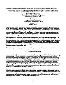
Fig. 6. Unresolved occlusion. The remote view is behind the barn, which does not exist in the 3D model. The system is unable to compute the occlusion.
In particular, when observing embedded cameras in AR, it is impossible to ascertain whether they are occluded or not. As an example, consider the case shown in Fig. 6. The remote camera is behind a barn. However, because the barn is not in the 3D model, it is impossible to compute such information. Furthermore, if the camera was behind the mountain and it was displayed as occluded, it would be impossible to know which object is the occluder (the barn or the mountain or a mountain further away?). As a solution we could send a drone (blimp) or a user to inspect every object in the line of sight until they found the occluder, but a more efficient method exists in the form of VPV: Variable perspective view improves overviews and partially solve occlusions. 6.2
Variable Perspective
6.2.1 Explorative Study We applied rapid usability testing as described by Pawson and Greenberg [21] to get an initial impression on the technique’s usability. During a demo of our overall system carried out at CHI 2011, five experts in the field of HCI and computer graphics were exposed to the technique. Instead of using questionnaires, we relied on informal conversation, as suggested in [21], guiding the discussion around the topic of interacting to change overview or discover spatial relationships, and collecting suggestions. As expected, participants showed enthusiasm at being able to control the effects of the technique, and were pleased with its fast response. One of them manifested a satisfaction at being able to see the horizon while increasing overview. The user was satisfied to be able to see the whole extent of the area by simply rotating in place and manifested that “seeing the horizon improved the navigation experience, while observing a larger area”. Another one was enthusiastic at the interaction that allowed him to discover occluded objects. “It’s like a tsunami effect, a wave that carries the objects to the top of the screen”. Notwithstanding these positive comments, some issues caused concern about the applicability of the technique. In particular, users declared that in some cases it is difficult to note the effect of the VPV. It is clear that the terrain is deformed but, it is unclear where the deformation takes place. In addition, the fact that the screen is full with information now poses a challenge in terms of cognitive load required to understand all information. To reduce this effect, we applied different representations for the different areas of the technique on fragment shader program. 6.2.2 Comparative Study We performed a formal study to analyze the effects of the VPV in a search and exploration task. We aimed at assessing usability and performance of the VPV by comparing it with a conventional overview interface: a self-orienting, forward-up map. The experiment followed a within-subject, repeated-measures design with the technique as independent variable (map, VPV), and dependent variables completion time, errors and subjective measure of cognitive load (measured using RTLX questionnaire). Tasks. the study focused on allowing participants to interact with the technique to discover the location of virtual objects. The focus was not only in finding virtual objects, but in assessing whether participants (mentally) establish the spatial relationship between these objects and the real-world. To represent a search and an exploration activity, we defined two categories of tasks: Category 1: Finding a real object, then a virtual object related to it, another virtual object, and finally real one (RVVR). This included subtasks for the user such as: • Locate the tallest building and find a cyan sphere near it. • Find a yellow cone near the sphere. • What building/location is the cone pointing at?
Category 2: Finding a virtual object, then another virtual object related to the first, and finally a real one (VVR). This included subtasks for the user such as: • Find a purple torus. • Find a yellow sphere to the left/west of it. • What building/location is the near the sphere? Methodology. The study took part in an area of approximately 2km2 around our university campus. The 3D scene was composed of virtual representations of buildings and extended with ten to fifteen virtual 3D shapes (torus, cones, spheres) with varying colours (cyan, yellow, magenta). The size and colour scheme, as well as the representation of the scene were chosen after a pilot study carried out beforehand during daytime. Thereby, we estimated what general schemes were visible under the lighting conditions. The final representation is a combination of wireframe and fill rendering modes, as shown in Fig. 4. We identified two locations around our campus for our two conditions. We defined six trials per location (six scenes with objects at different locations and six different sets of instructions). We randomized the initial location across participants, the conditions across locations, and the order of the subtasks per location. Our application prototype had two operating modes: a normal AR mode, and an overview mode. The participant could only access one mode at a given time, and was forced to press a button to switch to the other mode. The overview mode was associated to our 2 conditions and consisted of the map during the map condition; or the VPV during the condition of the same name. We logged the time on each mode, the overall duration of the task, all object selections, and errors when relevant. Before the measured trials, the participant was led to a third location for training. The procedure for the experiment was explained, and thereafter the participant tried the two techniques to get used to the controls and the instructions. Afterwards the participant was brought to the location for the measured trials of each condition. After each trial, the participant filled the TLX questionnaire, and subsequently a subjective questionnaire on usability. Upon finishing six trials, the participant filled an exit questionnaire on general experience with the technique. Thereafter, she/he was taken to the second location to perform the second condition. Comments from participants were noted down throughout the experiment for post- analysis. Apparatus. The platform for the experiment was Panasonic CF-U1 (screen resolution 1024x600) equipped with an external uEye Camera (800x600, 4.2mm wide angle lens). Location tracking was accomplished using a differential GPS (Ublox AEK-4H), and orientation with an inertial tracker (Intersense InertiaCube 3). Participants. Ten participants were recruited from the university, (9 male, 1 female, average age 27.6 years old). All participants had normal or corrected vision. Results. Six trials out of the 60 were not completed due to unrecoverable tracking errors and removed from analysis. A paired-samples t-test revealed a significant difference in the task duration for map and variable perspective technique, t (54) = -4.65, p < .01. Participants took significantly longer (M = 119.84s) to complete the task with the variable perspective technique than with a map (M = 73.38). The effect was still present when analysing results per each task type. For RVVR, t (27) = -3.6, p .9). Thus, workload for the vp condition (M =41.6) was not perceived different than that of using a map (M =39.01). Finally, the VPV was well received. Participants were enthusiastic at trying the interface, and there was a trend towards preferring the VPV (M =1.9, STD=1) over the map (M =2.7, STD=1.2), albeit not significant in a 7-point Likert scale. Three participants commented that they preferred the VPT when they had to find out relations between virtual and real, while other three noted that with the VPV they got a better idea of the orientation of objects. 6.2.3 Variable Perspective Benefits This initial comparative study provides preliminary results on usability and performance of our technique. On the one hand, people took more time using the VPV than with the map. Digital maps are well known and we didn't expect to get better quantitative performance with our novel technique (without proceeding to a longitudinal study). We noted a learning effect during the study and four participants reported it in their comments. Still, the ratings for workload did not differ, which suggests that performing with the VPV was not more demanding than with a map. Participants spent longer time in map and VPV than in AR. This, we believe, led to the perception participants had of separate sources of information. With the map technique, participants
needed to shift to another context. Conversely, the VPV kept them in a similar AR context even with a slightly higher execution time for the different tasks. Exit questionnaires showed that the VPV gave a significantly higher feeling of integration of virtual with real content, whereas, when performing with the map, participants mostly ignored AR. Kim and Dey [17] showed the advantage of this in tasks involving high levels of attention (e.g., driving). The study helped identify further perceptual issues that, when addressed, will help the VPV reach its full potential. For example, close, large physical objects can block the VPV. To counter the issue, the VPV needs to be extended with other, see-through occlusion management techniques (e.g., vanishing, ghosting). Beside perceptual issues, the outcomes of the experiment open up several paths for future work. There is a first indication that the VPV can benefit from a more intuitive user interface. The VPV extends overview for AR applications with the advantage of using the full screen to provide information. The combination with a registered video in AR allows direct access to the real world context. Thereby, users uncover spatial and topological information about the environment, while interacting with the technique to increase overview. Increasing overview: Overview can be changed dynamically by manipulating the rotation angle and the distance to the rotation. These two parameters allow fine control over how much deformation is applied to the terrain (angle) and where is it applied (distance). Fig. 7 illustrates the effect of changing the angle of rotation. To the left, the VPV occupies the whole screen, and there are little or no distant landmarks for the user to orient. To the right, the horizon is visible, showing distant landmarks for orientation and a larger portion of the terrain, although occlusions caused by changes in elevation become more prevalent. Unveiling occluded objects: Spatial relationships between occluded objects are discovered interactively by controlling the distance to the rotation, and the size of the transition zone. Fig. 8 illustrates the interaction to discover the positions of sensors. Note how these sensors appear packed together in the initial case, but become gradually separated as the interaction with the variable perspective changes the secondary viewpoint.
Fig. 8. Unveiling occlusions. Spatial relationships between occluded objects can be discovered by changing the distance d to the rotation.
6.3 Combining Techniques A combined version of VPV and multiview provides advantages worth mentioning. The views shared by other users or available from devices deployed in the field can be browsed and selected from the VPV. Thus the VPV provides a form of extended overview to the AR context, and the remote views complement this with zooming possibilities for remote points of interest. One advantage from the virtual views of the multi-view system is the possibility to detach them from the AR context, while still keeping it in view. This comes in handy to experience the variable perspective from a vantage point, as depicted in Fig. 9. The combination of virtual views and variable perspective AR allows the user to experience such view in an AR context. In the future we intend to experiment with this combination, in particular within a collaborative setting. 7
C O NC LUS I ON
AN D
F U TURE W OR K
We have deployed a set of techniques to support data visualization in outdoor AR applications. Our initial concern was to extend the overview for augmented reality, and provide a situated user with tools to observe large parts of the dataset in relation with the real world context where the data is generated. The techniques presented in this paper are based on view sharing, and perspective variations. As we developed these techniques, we found several ways to support different aspects of visual information search. The main contribution of this work is in describing a combination of techniques that enable data visualization in outdoor augmented reality. In the future, beside extending these techniques with features as suggested in the previous section, we would like to investigate interactions to discover simple ways to control the techniques. Furthermore, the next stage of our work is to extend these techniques to a collaborative setting, exploring interaction between users and the environment in outdoor AR. For the deformation of the terrain, we have only experimented with a single joint skeleton, but a more complex skeleton could be used to introduce several folding and unfolding effects in the same model. Furthermore, we have only experimented with deformation of the 3D information, but would like to explore how these deformations can be transferred to the mediated representation of the real world (i.e. video image), and what that implies for the user. Our initial evaluation was only exploring the performances of the techniques and the relation between real and virtual for AR/overview mode, we want to conduct further studies especially regarding spatial understanding of the scene under distorted conditions.
[3]
[4] [5] [6]
[7] [8] [9] [10]
[11]
[12]
[13]
[14] [15] [16] [17]
[18]
[19]
Fig. 9. Detached variable perspective view. The view is detached from the AR context to increase overview over the 3D model.
R E FE RE NC ES [1] [2]
T.H. Höllerer and S.K. Feiner, “Mobile Augmented Reality,” Telegeoinformatics LocationBased Computing and Services, 2004, pp. 1-39. B. Shneiderman, “The eyes have it: a task by data type taxonomy for information visualizations,” Proceedings 1996 IEEE Symposium on Visual Languages, vol. 0, 1996, pp. 336-343.
[20] [21]
G.R. King, W. Piekarski, and B.H. Thomas, “ARVino - Outdoor augmented reality visualisation of viticulture GIS data,” Proceedings of the 4th IEEEACM International Symposium on Mixed and Augmented Reality, B. Werner, ed., IEEE Computer Society, 2005, pp. 52-55. S. White, “SiteLens : Situated Visualization Techniques for Urban Site Visits,” Evaluation, 2009, pp. 1117-1120. N. Elmqvist and P. Tsigas, “A Taxonomy of 3D Occlusion Management for Visualization,” IEEE Transactions on Visualization and Computer Graphics, vol. 14, 2008, pp. 1095-1109. R. Bane and T. Hoellerer, “Interactive Tools for Virtual X-Ray Vision in Mobile Augmented Reality,” IEEE and ACM International Symposium on Mixed and Augmented Reality (ISMAR), IEEE Computer Society, 2004, pp. 231-239. E. Mendez and D. Schmalstieg, “Importance masks for revealing occluded objects in augmented reality,” 16th ACM Symposium on Virtual Reality, 2009, p. 247--248. C. Sandor, A. Cunningham, A. Dey, and V.-V. Mattila, “An Augmented Reality X-Ray system based on visual saliency,” 2010 IEEE International Symposium on Mixed and Augmented Reality, 2010, pp. 27-36. Y. Kameda, T. Takemasa, and Y. Ohta, “Outdoor See-Through Vision Utilizing Surveillance Cameras,” Third IEEE and ACM International Symposium on Mixed and Augmented Reality, 2004, pp. 151-160. B. Avery, W. Piekarski, and B.H. Thomas, “Visualizing Occluded Physical Objects in Unfamiliar Outdoor Augmented Reality Environments,” 2007 6th IEEE and ACM International Symposium on Mixed and Augmented Reality, 2007, pp. 1-2. Y. Wang, D.M. Krum, E.M. Coelho, and D.A. Bowman, “Contextualized videos: Combining videos with environment models to support situational understanding,” IEEE Transactions on Visualization and Computer Graphics (TVCG), vol. 13, 2007, p. 1568–1575. H.S. Sawhney, A. Arpa, R. Kumar, S. Samarasekera, M. Aggarwal, S. Hsu, D. Nister, and K. Hanna, “Video flashlights: real time rendering of multiple videos for immersive model visualization,” Eurographics Workshop on Rendering, 2002, pp. 157-168. M. Sukan and S.K. Feiner, “SnapAR: Storing snapshots for quick viewpoint switching in hand-held augmented reality,” Mixed and Augmented Reality (ISMAR), 2010 9th IEEE International Symposium, 2010, pp. 273-274. M. Jobst and J. Döllner, “Better Perception of 3D-Spatial Relations by Viewport Variations,” Visual Information Systems. Web-Based Visual Information Search and Management, Springer, 2008, p. 7--18. H. Lorenz, M. Trapp, M. Jobst, and J. Döllner, “Interactive MultiPerspective Views of Virtual 3D Landscape and City Models,” 11th AGILE International Conference on GI Science, 2008, pp. 301-321. S. Pasewaldt, M. Trapp, and J. Döllner, “Multiscale Visualization of 3D Geovirtual Environments Using View-Dependent Multi-Perspective Views,” Journal of WSCG, vol. 19, 2011, pp. 111-118. S. Kim and A.K. Dey, “Simulated augmented reality windshield display as a cognitive mapping aid for elder driver navigation,” Proceedings of the 27th international conference on Human factors in computing systems CHI 09, 2009, p. 133. C. Sandor, A. Cunningham, U. Eck, D. Urquhart, G. Jarvis, A. Dey, S. Barbier, M.R. Marner, and S. Rhee, “Egocentric space-distorting visualizations for rapid environment exploration in mobile mixed reality,” 2009 8th IEEE International Symposium on Mixed and Augmented Reality, 2009, pp. 211-212. U. Neumann, S. You, J. Hu, B. Jiang, and J. Lee, “Augmented virtual environments (AVE): Dynamic fusion of imagery and 3d models,” IEEE Virtual Reality (VR), 2003, p. 61–67. E. Veas, A. Mulloni, E. Kruijff, H. Regenbrecht and D. Schmalstieg, “Techniques for View Transition in Multi-Camera Outdoor Environments” Graphics Interface 2010 (GI2010), 2010, pp. 193-200. M. Pawson and S. Greenberg, “Extremely Rapid Usability Testing,” vol. 4, 2009, pp. 124-135.