AAPM 2014 Annual Meeting Best Practices in Pediatric Imaging
Exposure Factor Control in Pediatric Projection Radiography Charles E. Willis, Ph.D. DABR FAAPM Associate Professor Department of Imaging Physics The University of Texas M.D. Anderson Cancer Center Houston, Texas
[email protected]
Learning Objectives: • Appreciate why exposure factor control is necessary in pediatric projection radiography using CR and DR. • Identify the meaning of vendor-specific receptor exposure indicators and the new standardized receptor exposure indicators, and their indirect relationship to patient dose. • Explain how general radiographic techniques can be optimized using exposure indices to improve pediatric radiography.
Introduction • Both Computed Radiography (CR) and Digital Radiography (DR) are capable of producing acceptable diagnostic quality images over a wide range of exposures. • Control of acquisition exposure factors is necessary in order to manage the concomitant radiation dose to patients undergoing projection radiography examinations. • Control requires both measurement of the output and feedback to the operator to modify the input.
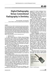
Without Auto-ranging
Seibert and Morin, Pediatr Radiol (2011) 41:573-581
With Auto-ranging
Seibert and Morin, Pediatr Radiol (2011) 41:573-581
Exposure factor creep occurs in CR and DR • A gradual increase in exposure factor selection by technologists is observed over time. – Under-exposed CR and DR images look noisy, and are likely to be
rejected by radiologists. – Over-exposed CR and DR images look less noisy, and are less likely to be rejected by radiologists. – Because CR and DR have a wide dynamic range, clipping is usually not evident until images are grossly over-exposed. Freedman M, Pe E, Mun SK, Lo SCB, Nelson M (1993) The potential for unnecessary patient exposure from the use of storage phosphor imaging systems. SPIE 1897:472-479. Gur D, Fuhman CR, Feist JH, Slifko R, Peace B (1993) Natural migration to a higher dose in CR imaging. Proc Eighth European Congress of Radiology. Vienna Sep 12-17.154.
What can be done about exposure factor creep? • To detect and reverse this trend, it is necessary to monitor a digital value that indicates the amount of radiation reaching the image receptor.
Why don’t we just rely on Automatic Exposure Control (AEC)? • AEC is not available in all settings (NICU, PICU, bedside) • AEC is challenging with pediatric patients – Often noncompliant – Anatomic dimensions small compared to AEC cells – Immobilization devices may introduce artifacts and dose penalty
• AEC controls exposure delivered but not other technical factors (kVp, SID, additional filtration, use of grid) • AEC must still be calibrated to deliver a specific target exposure.
Q1: Exposure factor control in pediatric DR requires which of the following items? 20% 20% 20% 20% 20%
1. 2. 3. 4. 5.
Automatic Exposure Control (AEC) Repeat/Reject analysis Autoranging A digital indicator of receptor exposure Personal supervision of technologists
10
4. A digital indicator of receptor exposure • Seibert and Morin, Pediatr Radiol (2011) 41:573-581. • Freedman M, Pe E, Mun SK, Lo SCB, Nelson M (1993) The potential for unnecessary patient exposure from the use of storage phosphor imaging systems. SPIE 1897:472-479. • Gur D, Fuhman CR, Feist JH, Slifko R, Peace B (1993) Natural migration to a higher dose in CR imaging. Proc Eighth European Congress of Radiology. Vienna Sep 12-17.154. • Gibson and Davidson, Acad Radiol (2012) 19(4):458–462.
Traditional Exposure Indicators • Historically, each vendor of CR or DR equipment invented its own Exposure Indicator • The name, symbology, exposure dependence, and calibration conditions for each were different.
Agfa
Fuji
Kodak
Konica
GE
Siemens
Philips
Canon
Swissray
IDC
lgM
S#
EI
S#
DEI
EXI
EI_S
REX
DI
F#
Traditional Exposure Indicators shortcomings • The variety and inconsistency of the vendor-specific exposure indicators created a problem for technologists who work with different CR and DR systems. • Standards organizations and medical physicists tried to solve this problem by proposing a standard scale that all vendors could adopt.
“The ‘Little’ Tower of Babel” Pieter Bruegel the Elder
AAPM TG 116 The American Association of Physicists in Medicine (AAPM) Task Group 116 published a report on exposure indicators in July 2009.
IEC Standard The International Electrotechnical Commission (IEC) published a standard for Exposure Index definitions in August 2008.
How does the new standard exposure indicator work? Two important features: • Exposure Index, EI
– Proportional to Air-kerma (exposure) at the receptor
• Deviation Index, DI
– How close did we come to the target?
DI change of 1 corresponds to 1 mAs “station” (Renard Series; ISO R’10) Table 1. Deviation Index vs. Target Exposure Deviation Index (DI)
Fraction of intended exposure (%)
-3
50%
-2
63%
-1
79%
0
100%
1
126%
2
158%
3
200%
How does the exposure indicator relate to the dose to the patient? • These indicators have one thing in common: they attempt to represent the average exposure at the image receptor in the shadow of the patient’s anatomy. • The dose to an individual patient can only be deduced from the exposure indicator when supplemented by information about the patient, examination, and technical factors. • If the exposure indicator correctly reports a doubling of the
exposure to the image receptor for the same examination of an individual patient, then the exposure (and dose) of the patient has likely doubled.
Example: What was the patient exposure in this CR exam? (AP Chest Tabletop) • Exposure indicator ? • lgM = 2.2 => 1 mR (9 μGy) • EIIEC = 900
• Patient thickness ? • 12 cm ˜ 3 HVL
• Scatter reduction grid? • None used
• SID? • 112 cm => SSD = 100cm
• ESE? • 1 mR x (112 /100)2 / 0.53 => • 10 mR (90 μGy)
Q2: What additional information is needed to deduce patient exposure from EI in a non-grid exam? 20% 20% 20% 20% 20%
1. 2. 3. 4. 5.
Backscatter factor HVL of beam exiting patient Target air kerma Both SSD and SID No additional information is necessary
10
4. Both SSD and SID • An additional assumption must be made about the attenuation of the x-ray beam through the patient tissue. HVL = 4 cm is not a bad guess for diagnostic x-ray energies. • NCRP Report No. 102 (1995) Appendix B Table B.8
Assuming this target! Depends on calibration!
So does this!
AAPM TG116 provided some guidance on how DI could be used Table 2. Exposure Indicator DI Control Limits for Clinical Images DI
Range Action
> +3.0
Excessive patient radiation exposure Repeat only if relevant anatomy is clipped or “burned out” Require immediate management follow-up.
+1 to +3.0 Overexposure
Overexposure: Repeat only if relevant anatomy is clipped or “burned out”
−0.5 to +0.5
Target range
Less than −1.0
Underexposed: Consult radiologist for repeat
Less than −3.0
Repeat
Why is this controversial? DI
> +3.0
% of Target
Range Action
200%
Excessive patient radiation exposure Repeat only if relevant anatomy is clipped or “burned out” Require immediate management follow-up.
Controversy When/why is it appropriate to repeat an over-exposed image? What level of management follow-up is recommended?
+1 to +3.0 Overexposure
120-200%
Overexposure: Repeat only if relevant anatomy is clipped or “burned out”
−0.5 to +0.5
89-112%
Target range
Too narrow? Radiologist approval necessary? In every instance?
Less than −1.0