EXAMPLE FOR CONTOUR PART PROGRAMMING (MANUAL) A CNC controlled vertical milling machine is used to perform endmilling of a simple part shown in Figure 13 . A feedrate of 500 mm/min is required for machining. The rapid traverse feedrate is 2500 mm/min (can be used for moving without machining) . A constant spindle speed of 1000 rpm is required. Only one cutter with a diameter of 20 mm is used. The cutter is initially at 40 mm above the table at the start point. Figure 13 shows the dotted line as the tool center path and solid lines as the part. Dimensions are specified in mm. Coolant is used during milling. Write a complete part program in the incremental system.
From start
to 10 mm from A
N100 GO I X60 YO Z-40 F2500 S1000 M03 -implies linear interpolation (GO1), tool is moved in X for a distance of 60 mm afterwhich the tool is turned on (M03) and is brought to the workpiece with a spindle speed of 1000 rpm. 10 mm from A to the point A N200 X10 YO F500 S1000 M08 -implies the beginning of the cut with coolant on (MO8) . Note that the feedrate is reduced to 500 mm/min. Point A to point B N300 X80 19
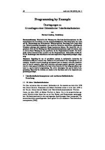
Point B to point C The cutter moves in the +Y direction to the point C . Use the Figure shown below to compute the distance BC .
30
P
30
BC =BB'-CB'=60+MB'tan22 .5=60=10tan22 .5=64.14 mm Thus the block BC is written as. N400 XO Y64.14 Point C to point D Fom the above figure, CD = NLti + OC = 42 .43 - 4.14 = 46.57 Since CD is at 45°, resolve it into X and Y as 46 .57/(2'''-) = 32.93 mm Thus the block for CD is written as N500 X-32 .93 Y 32 .93 20
Point D to point E After passing point D and prior to start the circular arc ED (whose center is N), use the Figure shown below.
We can write: i- +j- =100, j+y=10,i=x=0 .707R=7 .07 Solving all these, x = i = j = 7.07 mm, y = 2.93 mm N600 G03 X-7.07 Y2 .93 17.07 J7 .07 No cutting takes place between points D and E Point E to point F N700 X-40 Y-40 10 J40 F667 F is increased to 667 due to the cutter radius as given by the equation F = [(part contour radius + tool radius)/part contour radius] (required feedrate) = 40/30 (500) = 667 Point F to point A N800 GO1 XO Y-60 F500 Point A to start point N900 X-70 YO Z40 F500 M05 M09 This example demonstrates the need for the assistance of a computer in handling the calculations . 21
PROBLEMS 1.
A milling machine cuts a slot 2 in. long at 45° in the XY plane. The system resolution is 0 .0005 in. If the required feed rate along the slot is 4 in./min. Find the distance traveled in BLUs and the velocity of each individual axis. If the velocity of the y-axis decreases by 0.5%, what is the error in y-direction ?
2.
In which one of the following case, an open loop control system would be suitable ? Explain (a) (b)
A drilling machine table which always moves at the same speed and has the same load. A milling machine which moves at various speeds with different loads.
3.
A stepping motor with 250 step angles is coupled to a leadscrew through a gear reduction of 1 :1 . The leadscrew has a pitch of 4 mm. The worktable, driven by the leadscrew, must move a distance 100 mm at a feedrate of 300 mm/min . Determine (a) the number of pulses required to move the table (b) the required motor speed and pulse rate to achieve the desired table speed
4.
Referring to Problem 3, the mechanical inaccuracy can be described by a normal distribution whose standard deviation is 0.005 mm. If the range of the worktable axis is 500mm, determine (a) control resolution (b) accuracy and (c) repeatability . 1
5.
An end milling operation is carried out along a straight line path that is 13" in length on a CNC machining center. The cutting speed is 100 fpm. The end milling cutter has 2 teeth, feed of 0 .0025 in/tooth, and has a diameter of 0 .6325 in. . The pitch of leadscrew is 0.25 in/rev, and the optical encoder emits 400 pulses per revolution . Determine the feedrate, RPM of the motor, and pulse frequency of the encoder .
6.
The dimensions of the part shown in Figure are A'B' = 50 mm,B'C' = 40 mm, and the angle A'B'C' = 135° . The required feedrate is 100 mm/min . .Write a manual CNC program of the lines corresponding to the segments AB and BC. The radius of cutter is taken as 10 mm . Use incremental programming.
22
CNC NIACHINING CODES This is a list of codes commonly used in CNC machining. This list is not complete and differences can occur between different machines due to the manufacturer of the machine and the controller .
" " " " " " " " " " "
N code - sequence number. The sequence number is used to identify each block
within an NC program and provides a means by which NC commands may be rapidly located. G code - preparatory word . The preparatory function is used as a communication device to prepare the MCU. The G code indicates that a given control function, such as GO I, linear interpolation, is to be requested. X, Y and Z codes - coordinates. These give the coordinate positions of the tool . F code - feed rate . The F code specifies the feed in a machining operation. S code - spindle speed. The S code specifies the cutting speed of a machining process. T code - tool selection . The T code specifies which tool is to be used in a specific operation. M code - miscellaneous functions. The M code is used to designate a particular mode of operation for an NC machine tool. Most miscellaneous functions deal with opposing machine conditions ; for example, coolant on/off. I, J, and K codes. They specify the center of Arc coordinates from starting . f' code . It pause the next operation for thousands of seconds. D and H codes. They specify the offsetting values . !. codes. It defines the number of repetitions of a cycle .