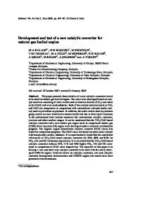
MATEC Web of Conferences 87 , 02021 (2017)
DOI: 10.1051/ matecconf/20178702021
ENCON 2016
Emission Treatment towards Cold Start and Back Pressure in Internal Combustion Engine against Performance of Catalytic Converter: A Review 1,a
1
1
1
A.M. Leman , Fakhrurrazi Rahman , Afiqah Jajuli , Supaat Zakaria and Dafit Feriyanto
1
1
Faculty of Engineering Technology, Universiti Tun Hussein Onn Malaysia (UTHM) 86400, Parit raja, Batu Pahat, johor, Malaysia
Abstract. Nowadays, regulation for the vehicles emissions has becoming more stringent in order to reduce the effect of pollutant gases that was being released by the vehicles exhaust. The development of catalytic converter is to resolve the pollution emission aspect . There are lots of improvements done by the researchers towards improving catalytic converter, yet there are still key issues which give negative impact to the environment. One of the problems that are being concern by among of researchers is the cold-start and back pressure problems that usually occur in the composition of catalytic converter. Presented here is a review of cold-starts and back pressure problems together with several alternatives taken by not affecting the performance of vehicles engine and fuel consumption. The review also includes alternative system development and selection of materials to resolve these problems.
1 Introduction In 21th century, the number of vehicles grew more quickly which increases the total of air pollution from internal combustion. These pollutant gases influence to give bad effect to the human health and also surrounding environment [1]. Vehicles nowadays facing serious issues with the engines combustion gases that released high pollutant gases such as Unburned Hydrocarbon (HC), Caron Monoxide (CO) and Nitrogen oxide (NOx) through the exhaust pipeline [2]. Most vehicles with gasoline fuelled were attached with three way catalyst in catalytic converter that gives an alternative way to reduce pollutant gaseous from the exhaust emission [3]. Mansha et al., (2013)[4] stated that there are two common methods that were usually being used in reducing the harmful gases that were adapted from the emission gases of automobiles exhaust by improving the technology of automobiles engine and composition of vehicles fuel. The catalytic converter was a special device that is originally designed to convert the pollution gaseous from being released into the atmosphere. The conversion still releasing amount of pollutant throughout the warm-up phases until the catalytic converter reaches out its light-off temperature. Thus, this kind of problem has becoming barriers to achieve future standard of emission [3]. Consequently, there are several ways of studies that involved the combustion of vehicles engine which also have a relation with the engine control and after treatment process that a
were been investigated to reduced cold-start emission and back pressure that usually occurs in the vehicles engine combustion [5][6]. According to Steven et al., (1995)[7] the cold start emission is closely related with the thermal control in catalytic converter. A better technique to treat the cold start emission is by using compact insulation which could continuously give a better impact towards thermal conductance and maintaining the heat between the combustion system by providing low conductivity and also high conductivity for the engines heat rejection from the converter during the engine operation. This paper aims to review the techniques by previous researchers to improve the performance of cold-start system, evaluating the findings and discuss the some strategies to overcome the cold start problems from the vehicles exhaust combustion based on the vehicles system performance and also materials optimization.
2 Catalytic Stability
Converter
Design
and
Catalytic converter is a device that is used to reduce the pollutant gaseous that originally comes from the internal combustion of vehicles engine. Catalytic converter is a stainless steel container that is attached alongside the exhaust pipeline and inside the container is a porous ceramic or metallic structure through which the exhaust gas flows [8]. It is usually being placed between engine
Corresponding author:
[email protected]
© The Authors, published by EDP Sciences. This is an open access article distributed under the terms of the Creative Commons Attribution License 4.0 (http://creativecommons.org/licenses/by/4.0/).
MATEC Web of Conferences 87 , 02021 (2017)
DOI: 10.1051/ matecconf/20178702021
ENCON 2016 manifold that connected with the tailpipe of vehicle exhaust system. The combustion occurs in the vehicles engine produced pollutant gases and will be pass through the tailpipe before undergo chemical reaction with the catalyst within the porous wash coat in the converter to produce a harmless gaseous which is readily to be released to the atmosphere. There are two types of catalytic converter which is classified as Two-Way or Three-Way catalytic converter. The Two-Way converter only works on two types of gases which are CO and unburned HC while the NOx is controlled by exhaust gas recirculation (EGR) system and by retarding the ignition timing [9]. Early manufactures used loose granular ceramic to manufactured ceramic converters with the gas passing through the packed spheres. Since it is difficult to keep the spheres in place, many converter developers opted for ceramic monolith which offers various advantages. It offers several advantages such as lower mass, smaller volumes and easily for packaging process [10]. The wash coat that is applied for the ceramic converters monolith walls composed of porous, high surface area inorganic oxides ZrO2 (Zirconia), CeO2 (Ceria) and γ-Al2O3 (gamma alumina).
Figure 1. Single Channel Concept [13]
Noble metal catalysts, such as Platinum (Pt), Palladium (Pd) and Rhodium (Rh), are deposited on the surface and within the pores of the wash coat [11]. There are several models in predicting the pressure loss of channel substrate in the catalytic converter by approaching various types of cell shapes. Common model used by vehicles is the classic model discovered by HagenPoiseuille. This model purposed a laminar flow through a circular duct [12]. The evolution for design and optimization of the monolith in the catalytic converter is increasing from time to time. It is because the honeycomb material is available in various type of shapes and dimension which including the hexagon, square, triangle, circle and also sinusoidal. Figure 1 shows the single channel concept of monolith. The improved techniques in treating the honeycomb structure is by using the sub-grid scale modelling displays in Figure 2.
Figure 2. Sub-Grid Scale Channel Concept [14]
3 Cold Start Emission
The cold-start issues among the researchers in automotive engineering have become one of new topic that needs to be discuses and solve in order to develop new emissions treatment techniques. Until it reaches the light-off temperature, a catalytic converter remains essentially ineffective. The understanding about characteristics of catalytic converter is important especially during the cold-start period in order to improve the performances of cold-start. There are two common methods used in handling the cold-start which is passive and active methods. The passive method is referring on the optimization of the exhaust system design which including the modification made upon the catalytic converter or by changing the position of the converter relative to the vehicles engine. On the other hand, the active method is based on the additional energy used to increase the performance of converter especially for the exhaust system temperature during the cold start. This type of method requires heating the preheating process
2
MATEC Web of Conferences 87 , 02021 (2017)
DOI: 10.1051/ matecconf/20178702021
ENCON 2016 engine system as it can result in deterioration to the performance measure of engine setup. Hence, the pollutant emission gaseous can be significantly reduced by shorten the time taken for the catalytic converter to reach light-off temperature during a cold start. This is because most vehicles emit pollutant gaseous during the legislated driving cycles. (Moore et al., 1993)[20] stated that during Federal Test Procedure (FTP), the pollutant emissions released by the vehicles was about 50% to 80%. It is occurs before the catalytic converter reach light-off temperature. According to Heywood (1998) [21], it was found that the largest contribution of HC and CO emissions occur during the first minutes of engine operation. Figure 4 shows the efficiency of catalytic converter for HC and CO conversion against temperature of the engine combustion.
for the catalytic converter. Both methods usually do not need additional devices and also not increasing the cost to overcome the cold-start problems. The cold performance of vehicles is closely related to the fuel consumption of engine performance. According to Kunze et al., (2006) [15], when engine starts to warm-up from temperature between 25oC – 90oC, the fuel consumption during this period is decreasing in an average about 10%. Hence, for the vehicle that only involve in short distance trips, it needs to improve the fuel consumption especially during the warmup phase because the engine could not reach the optimum temperature for the catalytic converter to be activated which could causes cold start emission. (Roberts et al., 2014)[16] claims that the average of the cars travel in Europe is around 10 km while Burke et al. (2010) [17] state that in United State of America, the mean length of travelling distances of vehicles are less than 15km. The data presented in Figure 3 shows the energy thermal balance occurs in the vehicles cylinder during the warm-up stages.
Leading to these issues, there were several approaches are taken to overcome the cold-start problems. The energy waste from the exhaust combustion can be one of the alternatives to heat up the catalytic converter temperature by having heat exchanger applications. Kumar et al., (2013)[22] investigate that the temperature of exhaust gases that flows from the internal combustion engine was from 300oC to 900oC which is depending on the engine load. The exhaust gas is one of the waste energy that is released and it would give benefits in rising up the catalytic temperature if the waste energy can be jointed to the catalytic converter which is also known as energy capture. It is not only achieved better accelerated temperature rising, the fuel consumption of the vehicles engine also can be reduced. It must be noted that the heat extraction from the exhaust temperature may rise up the light-off timing which also would increase the level of pollutant gaseous. The idea to conduct the energy capture must be carefully considered as the usual length between exhaust manifold and catalytic converter can be over than 0.1m length and Zhao and Winterbone (1993)[23] state that the temperature would reduce about 200oC between that distance. Another consideration also must be taken that any addition for energy capturing system will give some additional weight to the vehicles which would affect the fuel consumption to be increased.
Figure 3. Energy balance that occurs in the vehicles engine during warm up stages and alternatives in solving cold start problems [18]
There is only 4% of heat that is remained in the lubricant during the energy transfer process occurs in the engine through combustion which resulted low warm-up rate. Temporarily, another 32% is reserved in the engine metal warm-up at the engine block that provides very little benefits except it will conserve to increase engines cylinder temperature (Roberts et al., 2014)[16]. Still there is 52% energy from the combustion is expelled from the engine system as waste heat. Clearly, the needs to improve cold start emission by utilizing the waste heat in the engines to ensure that the lubricant temperature may rise in quicker time. Brito et al., (2012)[19] stated that the released energy from the engine combustion will be then released to the exhaust gas about 15% up to 40%.
Will and Boretti (2011)[24] had conducted an investigation on the heat exchanger that applied from the exhaust gas directly towards the lubricant device heat exchange. From their investigation, it showed an improvement for fuel consumption efficiency about 7% without installing heat exchanger system device from the exhaust combustion. Other than that, the lubricant heat exchange device also reduced 2% of HC emission together with reduction of 19% of NOx and 27% of CO emissions. In order to avoid emission distress, the
Cold start problems can be said that it is one of the difficult problems to be solved as the relation system in the engine combustion is complex. There is a need to apply a system that can fasten the warm-up temperature without making any additional of thermal inertia to the
3
MATEC Web of Conferences 87 , 02021 (2017)
DOI: 10.1051/ matecconf/20178702021
ENCON 2016 about 58.7% from the inlet energy is being moved to the coolant system due to operating temperature limitations of the TEG. Thus, the electrical generation produced from the process can be only 3% from the total exhaust gas energy.
location of heat exchanger is placed near to the catalytic converter. It is argued that by increasing the lubricant temperature may give other positives effects for the engine combustion by reducing friction in the engine piston.
Figure 5. Thermoelectric junction of two dissimilar materials of p-type and n-type [16]
Kollman et al.,(1994)[26] overcome the cold-start problem by heating the catalytic converter with an external combustion Hydrogen gas that is added to the vacuum insulation which contains a small amount of metal hydride [27]. The function of the metal hydride is to electrically heat the pressure of the hydrogen. The temperature of the hydride is controlled which directly varies with the pressure of the hydrogen inside the catalytic converter. When the metal hydride is at low temperatures, the hydrogen gas is absorbed by the metal oxide and the heat conductance is only affected by the conductance of the insulation. When the metal oxide is heated, the hydrogen gas is released and its pressure
Figure 4. HC and CO emission against engine combustion temperature [24]
Another way to manage the cold-starts problems from the vehicles engine combustion is by using thermal electric applications. The application of thermal electricity is generated using the Seebeck Effect which can eventually operate thermal energy system [25]. It is caused by the existing of electric voltage that exists across the junction of two dissimilar materials which will result temperature difference such as shown in Figure 5. This alternative ways offers benefits on fuel consumption and produced better emissions which also related in reducing the engines load over engine alternator. Brito et al., (2012) [19] had managed the investigation for thermal electricity application which is also known as thermoelectric generator (TEG). The heat exchanger process occurs between the TEG and the exhaust gas is using the heat pipes which act as a medium. Conversion of the exhaust combustion gases to the electrical energy power output was still in limit order which just only 1%, showing that the conversion is still limited. Therefore, it can be conclude that the application of TEG to the engine combustion can brings new alternative ways for recapturing waste thermal energy from the exhaust combustion gases. Kumar et al., (2013)[22] proved that TEG may recover the energy in the range of 64% from the exhaust combustion gas the enters the device and
begins to increase. Figure 6 shows the catalytic converter structure with the vacuum insulation. Figure 6. Vacuum insulation installed in catalytic converter [28]
4
MATEC Web of Conferences 87 , 02021 (2017)
DOI: 10.1051/ matecconf/20178702021
ENCON 2016
4 Back Pressures The installation of catalytic converter in the exhaust system has been approved by numerous researchers where the catalyst surface needs to have a sufficient area for treating the gases to meet the emission limits. However, this procedure increases the pressure drop, resulting in engine power losses and fuel wastage. Indeed, an increased pressure drop is challenges that need to overcome. Typically, an engine will lose about 300 w of power per 1000 pa of pressure loss [29]. The catalyst and filter materials placed inside the catalytic converter increase back pressure. This increase in back pressure causes more fuel consumption, and in most cases, engine stalling might happen. The filtration efficiency and back pressure are interrelated. If maximum filtration efficiency using very fine grid size wire meshes, is achieved, the back pressure will also be increased, which causes more fuel consumption. On the other hand, if larger grid size wire meshes are used, back pressure will be less, but the filtration efficiency will also be reduced, which does not help in meeting the present emission norms. With the help of computational fluids dynamics (CFD) analysis, it is attempted to find out the optimum solution to get maximum filtration efficiency with limited back pressure developed inside the catalytic converter [30]. According to Lashmikanti and Keck (2004)[31] there are two major components that are related to the pressure drop in the catalytic converter which are substrate and flow distribution devices. Figure 7 shows that the substrates commonly in pellet forms by the usage of γ-Al2O3 particles is used to replace the honeycomb monolith structure that gives positive impact in terms of ensuring a lower pressure drop by having a high open frontal area. Moreover, an increase in cell density is accompanied by a reduction in wall thickness to compensate for the increase in backpressure. The substrate length, cross-sectional area, and cell shape are also important parameters that have been investigated by few researchers. According to (Day, 1997) [32] and Miyairi et al., (2003) [33], they have identified the importance of cell shape in the overall performance of a catalytic converter. Pressure drop, heat, and mass transfer characteristics have been calculated in relation to different cell shapes.
Figure 7. Pellets that replaced substrate used as the conversion for pollutant gases in catalytic converters [32]
The combinations of these requirements will provide a better performance for the vehicles ventilation. Karuppusamy et al., (2013)[35] have conducted an experiment related to the flow in catalytic converter in order to minimize back pressure in the several types of converter based on different diameter, length and inlet cone angle of the monolith for the catalytic converter. It is observed that the back pressure for the converters that have larger diameter. The result from the research shows that increase in inlet cone length will reduces the backpressure and also reduces the recirculation zones in the catalytic converter. Figure 8a and 8b shows different inlet cone angle and different catalyst length of catalytic converter used to compare the back pressure in the catalytic converter.
Figure 8a. Catalytic with higher cone length and angle [32]
Other investigation done by Rajadurai et al., (2006) [34] state that the Knitted wire mesh substrates with different geometry and channels gives positives impact towards the back pressure occurs in the catalytic converter. The basic requirements for better flow in the catalytic converter were lower in back pressure, system weight and also better flow of gaseous emissions. Figure 8b. Catalytic with less cone length and angle [32]
5
MATEC Web of Conferences 87 , 02021 (2017)
DOI: 10.1051/ matecconf/20178702021
ENCON 2016 8. Ganessan, V. Internal Combustion Engine. Second Edition, McGraw Hill (2004). 9. Mansha M. Shahid. E.M., Qureshi A.H. Control of Combustion Generated Emissions from Spark Ignition Engines: A Review, Pakistan Journal of Engineering and Applied Sciences, Vol. 11, pp 114128 (2012). 10. Heck, R.M. and Farrauto, R.J. Catalytic Air Pollution Control. New York: Van Nostrand Reinhold (1995). 11. Pontikakis, G.N. Modelling, Reaction Schemes and Kinetic Parameter Estimation in Automotive Catalytic Converters and Diesel Particulate Filters,” Published Thesis (2003). 12. White F.M. Fluid Mechanics. Singapore:Mc-Graw Hill, Inc (2003). 13. Deutschmann O., Maier L. I., Riedel U., Stroemann A.H. and Dibble R.W. 2000, “Hydrogen assisted catalytic combustion of methane on platinum, “ Catalysis Today. 59, pp. 141-150. 14. Miyairi Y., Aoki T., Hirose S., Yamamoto Y., Makino M., Miwa S., Abe and F.. 2003. Effect of Cell Shape on Mass Transfer and Pressure Loss. SAE International, 2003-01-0659 (2003). 15. Kunze K, Wolff S, Lade I, Tonhauser J. A systematic analysis of CO2-reduction by an optimized heat supply during vehicle warm-up. SAE technical paper 2006-01-1450; (2006). 16. Roberts A., Brooks R. and Shipway P. Internal combustion engine cold-start efficiency: A review of the problem, causes and potential solutions. Journal of energy conversion and management, Vol. 82, pp 327 – 350 (2014). 17. Burke RD, Brace CJ, Hawley JG, Pegg I. Review of the systems analysis of interactions between the thermal, lubricant, and combustion processes of diesel engines. Proc Inst Mech Eng Part D: J Automobile Engineering; 224(5):681–704 (2010). 18. Trapy JD, Damiral P. An investigation of lubricating system warm-up for the improvement of cold start efficiency and emissions of SI automotive engines. SAE technical paper 902089 (1990). 19. Brito FP, Martins J, Goncalves L, Sousa R. Temperature controlled exhaust heat thermoelectric generation. SAE technical paper 2012-01-1214 (2012). 20. Moore, Wayne R. and Mondt, J. Robert. "Predicted Cold Start Emission Reductions Resulting from Exhaust Thermal Energy Conservation to Quicken Catalytic Converter Lightoff," SAE International, paper No. 931087 (1993). 21. Heywood, J. B. Motor vehicle emissions control: past achievements, future prospects. In Handbook of Air Pollution from Internal Combustion Engines, Academic Press (1998). 22. Kumar S, Heister SD, Xu X, Salvador JR, Meisner GP. Thermoelectric generators for automotive waste heat recovery systems. Part I: numerical modelling and baseline model analysis. J Electron Mater; 42(4):665–74 (2013).
5 Conclusions Through this review study, it is notice that cold-start is one of the important issues that need to be concern for the performance of vehicles engine combustion. There are a few strategies used by the researchers to improve the cold-start performance in a technical ways. The most important factors in solving cold start performance are to improve the light-off temperature during the warm-up stage. Thus, modification of catalytic converter is an important aspect that needs to be concern in order to reduce the pollutant gaseous from being exposed to the atmosphere especially during the cold-start period. Other than that, the flows of the emission gaseous in the catalytic converter also need to be discussed in order to make sure the flow of the emissions is treating in a better way to avoid engine power losses and fuel wastage.
Acknowledgement The authors would like to thank the Ministry of Higher Education Malaysia and Universiti Tun Hussein Onn Malaysia (UTHM) through the funding supported FRGS grant under No Vot. 1216 and Centre for Graduate Studies – UTHM.
References 1. Seinfeld, J.H. Air Pollution: A Half Century Progress. Environmental and Energy Engineering, 50(6):10961108 (2004). 2. Kalam M. A. Masjuki H. H, Mohd. Redzuan, Fuad M. A., Mohibah M., Halim K.H., Mahlia T. M. I., Abdul Ishak. Development and test of a new catalytic converter for natural gas fuelled engine. Sadhana. Vol. 34, Part 3, pp 467-481 (2009). 3. Denis Igorevich Andrianov, Chris Manzie and Michael John Brear. A Methodology for Minimising Emissions Constrained Cold Start Fuel Consumption. SAE International (2012). 4. Mansha M., Qureshi A.H., Chaudry I.A. and Shahid E.M. Three Ways Catalytic Simulation of EngineOut Exhaust Emission. Journal of Quality and Technology Management Volume IX, Issue I, pp 57 – 68 (2013). 5. Roberts C. E. and Stanglmaier R. H. Investigation of intake timing effects on the cold start behavior of a spark ignition engine, SAE International, Paper No.1999-01-3622 (1999). 6. H. Santoso and W. K. Cheng. Mixture preparation and hydrocarbon emissions behaviors in the first cycle of SI engine cranking, SAE International, Paper No. 2002-01-2805. (2002). 7. Steven D. Burch Thomas F. Potter Matthew A. Keyser. Reducing Cold-Start Emissions by Catalytic Converter Thermal Management. National Renewable Energy Laboratory. U.S. Department of Energy. (1995).
6
MATEC Web of Conferences 87 , 02021 (2017)
DOI: 10.1051/ matecconf/20178702021
ENCON 2016 23. Zhao Y, Winterbone DE. A study of warm-up processes in SI engine exhaust systems. SAE technical paper 931094 (1993). 24. Will F, Boretti A. A new method to warm up lubricating oil to improve the fuel efficiency during cold start. SAE technical paper 2011-01-0318; (2011). 25. Yu C, Chau KT. Thermoelectric automotive waste heat energy recovery using maximum power point tracking. Energy Convers Manage 50(6):1506–12 (2009). 26. Kollman, K. Abthoff, J. and Zahn, W. Three-Way Catalysts for Ultra-Low-Emission Vehicles. Automotive Engineering, 17–22 (1994). 27. Cooper, B. The future of catalytic systems. Automotive Engineering, 9–12 (1992). 28. Burch S.S. and Keyser M.A. Applications and Benefits of Catalytic Converter Thermal Management. National Renewable Energy Laboratory (2003). 29. Pannone G.M and Mueller J.D. A comparison of conversion efficiency and flow restriction performance of ceramic and metallic catalyst substrate,” SAE International, 2001-01-0926 (2001). 30. Balakrishna B.,Srinivasarao Mamidala. Design Optimization of Catalytic Converter to reduce Particulate Matter and Achieve Limited Back Pressure in Diesel Engine by CFD. International Journal of Current Engineering and Technology. EISSN 2277 – 4106, P-ISSN 2347 – 5161 (2014). 31. Lashmikantha M. and Keck M. Optimization of exhaust systems. SAE International, 2002-01-0059 (2002). 32. Day J.P. Substrate effects on light-off – part (ii) cell shape contributions, SAE International, 971024 (1997). 33. Miyairi Y., Aoki T., Hirose S., Yamamoto Y., Makino M., Miwa S., Abe and F.. 2003. Effect of Cell Shape on Mass Transfer and Pressure Loss. SAE International, 2003-01-0659 (2003). 34. Rajadurai S., Jacob S., Serrell C., Morin R. and Kircanski Z. Wiremesh Substrates for Oxidation.TWC and SCR Converters; GPC Advanced Propulsion and Emission (2006). 35. Karuppusamy P. Senthil R. Design, Analysis of Flow Characteristics of Catalytic Converter and Effects of Backpressure On Engine Performance. International Journal of Research in Engineering & Advanced Technology (IJERAT), Volume 1, Issue 1. ISSN: 2320 – 8791 (2013).
7