IEEE TRANSACTIONS ON IMAGE PROCESSING, VOL. 10, NO. 4, APRIL 2001
609
Efficient Optical Camera Tracking in Virtual Sets Yiannis S. Xirouhakis, Athanasios I. Drosopoulos, and Anastasios N. Delopoulos, Member, IEEE
Abstract—Optical tracking systems have become particularly popular in virtual studios applications tending to substitute electromechanical ones. However, optical systems are reported to be inferior in terms of accuracy in camera motion estimation. Moreover, marker-based approaches often cause problems in image/video compositing and impose undesirable constraints on camera movement. Present work introduces a novel methodology for the construction of a two-tone blue screen, which allows the localization of camera in three-dimensional (3-D) space on the basis of the captured sequence. At the same time, a novel algorithm is presented for the extraction of camera’s 3-D motion parameters based on 3-D-to-two-dimensional (2-D) line correspondences. Simulated experiments have been included to illustrate the performance of the proposed system. Index Terms—Camera motion estimation, line correspondences, optical tracking systems, primitive polynomials, virtual sets, virtual studios.
I. INTRODUCTION
T
HE rapid development in computer science has attracted a major part of the entertainment industry during the past few years. The recent advances in image processing, video technologies and computer graphics, as well as the increasing computational power provided by computer hardware are widely endorsed in video production. Virtual studios are being used in the video industry for a variety of productions, resulting in some very interesting visual effects, with the weather report programs being the most common among them. Video sequences produced by such systems are basically compositions of distinct natural or synthetic sequences, which are either pre-loaded or captured in real time. In the most common case, the composed sequence (often referred to as virtual set) consists of a live video and a pre-loaded synthetic or natural imagery [6]. In this context, increasing attention is given to such systems, especially after the guidelines of the MPEG-4 standard regarding object-oriented and synthetic-natural-hybrid coding. A virtual studio system consists of mainly three modules, namely the camera tracking, the rendering and the compositing module. The latter traditionally involves a blue screen background, against which foreground action is captured, and a chromakeying technique for foreground and background separation. Foreground action is then combined with the available background imagery. In this way, the television meteorologist ap-
Manuscript received November 10, 1999; revised December 15, 2000. The associate editor coordinating the review of this manuscript and approving it for publication was Prof. Steven D. Blostein. The authors are with the Image, Video, and Multimedia Systems Laboratory, Department of Computer and Electrical Engineering, National Technical University of Athens, GR-15773 Athens, Greece (e-mail:
[email protected]). Publisher Item Identifier S 1057-7149(01)02473-3.
pears to be standing in front of a weather map, while he/she is actually located in front of a blue screen. Practically, the compositing module replaces the regions of key-color in the live video with the pre-loaded background. The traditional chromakeying techniques have been modified and extended to suppress artifacts and improve compositing results (see for example [8], [11]). The rendering module is responsible for the alignment of the captured foreground with the background scene. The latter is mainly available either as a rendered sequence or a virtual model/world. In the first case, the background sequence must be transformed so as to be coherent with the foreground one, while in the second case, the background virtual scene is rendered by a virtual camera with respect to the foreground real camera motion. The camera tracking module is by all means the most crucial part of virtual studio systems, since it determines the alignment of the live video with the available imagery. Until the beginning of the decade, the camera tracking module was absent from virtual studios, limiting the systems’ capabilities to applications like the weather report TV programs. Since then, a number of tracking schemes have been proposed to extend traditional virtual studios capabilities. Camera tracking systems in virtual studios are generally classified into two broad categories, namely the electromechanical and the optical ones (or even combinations of both). Several virtual studio systems have been developed as prototypes or as commercial products, including Elset, 3DK, Synthevision for electromechanical and Cyberset, Mindset for optical tracking among others (see [6] for details). Electromechanical tracking has been widely adopted, since it can be highly accurate. In such approaches, servo-control mechanisms are employed to control the camera when 3-D camera motion is pre-determined (active systems). When the latter is unknown, appropriate sensors are mounted on the camera framework to detect its egomotion (passive systems). However, electromechanical systems are reported to require extensive time-consuming calibration procedures, while at the same time sensors suffer from random vibrations. Moreover, the designated equipment can be very expensive, especially when increasing the desirable degrees of freedom in camera motion. Optical tracking systems rely on image processing schemes to extract camera motion on the basis of the frames currently captured. For this purpose, the singlecolored blue screen is extended to incorporate appropriate reference features for two-dimensional (2-D) tracking, such as points or straight lines. Although in this way the problems of timecostly calibration and vibrations of the camera are overpassed, it can be seen that optical systems fail when the referenced features are out of focus, occluded or even out of view. It is moreover reported that markers cause compositing problems, since they must be made distinguishable from the blue background [6].
1057–7149/01$10.00 © 2001 IEEE
610
In the present work, the problem of constructing an appropriate blue screen, which allows for both the immediate localization of the camera’s field of view and the estimation of three-dimensional (3-D) camera motion, is addressed. The proposed optical tracking system eliminates the aforementioned common problems, leading to highly accurate 3-D camera motion estimation, without being affected by abrupt changes in the camera field of view or causing any compositing difficulties. The main idea in the construction of the blue screen relies on the utilization of two close levels of blue, in the place of the traditional single-colored blue screen. Similar approaches have been followed in [2] and [23], in the sense that the single-colored blue screen has been extended to contain more levels of blue. In [2], a nonuniform blue background is employed to facilitate 2-D motion estimation using the optical flow method presented in [9], which is reported to be robust even for defocused subjects. However, the utilization of such an approach is proved to suffer from common inaccuracies of 2-D motion estimation schemes and complicates the choice of the blue shades when attempting to extract shadows. In [23], the respective commercial product utilizes a two-tone blue screen and pattern recognition methods to extract the camera field of view. However, according to [23], the blue screen is derived on the basis of ‘trial and error’ and the utilized pattern recognition scheme, though not analyzed, is reported to require significant computational power. In the present work, the proposed two-tone blue screen is constructed on the basis of the well-established theory of algebraic coding, based on primitive polynomials and binary maximal length codes [7] of the one-dimensional (1-D) space. The 1-D case is appropriately extended to the 2-D case (in fact, the case of 3-D planar surfaces) for the construction of a blue screen of the desirable size. In particular, the proposed methodology involves dividing the background in rectangles of equal size and painting each rectangle using darker or lighter blue. In this way, every blue screen region exceeding a pre-determined size (w.r.t. the minimal expected camera field of view) is uniquely localized in the entire background. Some preliminary ideas on the construction of the blue screen on the basis of maximal sequences were presented in [3], [21]. In parallel, particular attention is paid to the estimation of the 3-D camera motion. In [3], camera motion estimation was performed on the basis of reference points extracted from the rectangles’ common boundaries, which in turn were fed to an appropriate 3-D motion estimation algorithm [18], [19], [15], [20] w.r.t. the projection model employed [17]. In [21], 3-D motion estimation was performed on the basis of 2-D line features solving a set of linear homogeneous equations in the unknown rotation parameters. Compared to both approaches, the present one proves to be superior in terms of accuracy. In this approach, a novel algorithm for 3-D camera motion estimation is proposed based on 3-D-to-2-D line correspondences. For similar tasks, a number of algorithms have been proposed in the literature, including [14], [22], [16], [12] among others, concentrating mainly on the 2-D-to-2-D case (for a thorough review on 3-D motion and structure from feature correspondences see [10], [4]). The proposed algorithm considers the 3-D-to-2-D correspondences case for the implicit grid-lines extracted from the proposed blue screen. A robust and elegant solution is pre-
IEEE TRANSACTIONS ON IMAGE PROCESSING, VOL. 10, NO. 4, APRIL 2001
sented based on the singular value decomposition of a simple matrix. The proposed blue screen construction method and the 3-D motion estimation algorithm are efficiently combined providing improved 3-D camera motion estimates. In Section II, the algorithm is presented in the form of sequential tasks and all issues involved are underlined and discussed. In Section III, the proposed methodology in the construction of the blue screen is described, along with the appropriate extensions of the employed fundamental theory of 1-D maximal sequences. Section IV next establishes the estimation of 3-D camera rotation and translation parameters, while Section V introduces the corresponding error analysis. Section VI provides the interested reader with practical algorithmic details and implementation guidelines, while appropriate simulation results are included to illustrate the robustness of the proposed approach. Finally, Section VII summarizes both the theoretical and practical contributions of this work. II. SYSTEM OVERVIEW In this section, the proposed algorithm is presented in the form of sequential tasks. In addition, optical tracking systems’ problems are underlined and discussed, in relation to the proposed approach. A. Designing an Optical Tracking System Optical camera tracking systems in virtual studios take advantage of the fact that each captured frame contains an already large amount of information about the background, which could be used for tracking apart from background segmentation. In this sense, appropriate features that can be detected and tracked through time, are incorporated onto the blue screen. For camera tracking purposes, the employed features should be sufficiently large in number, distinguishable from the uniform blue background and from each other in some sense, for example distinct in color tone or relative ordering. It can be seen, that knowledge of their actual or even relative position on the background is not sufficient, since the camera field of view is unknown through time and feature distance is determined by the projection model and the camera’s 3-D position. Overall, the following issues must be taken into consideration: 1) total number of blue color levels should be kept considerably small to permit efficient chromakeying and even satisfactory shadows extraction (if needed); 2) features employed should be distinguishable to permit localization of the camera field of view; 3) features set should locally contain sufficient information, even when an important portion of the background is occluded by foreground action in each frame captured; 4) tracking scheme should allow abrupt camera movement in all directions. In general, it can be seen that most of the existing systems do not fulfill all of the above requirements. For example, systems based on optical flow estimation pose difficulties in chromakeying, due to the large number of blue levels required, whereas systems based on markers suffer from partial occlusion or absence of markers in the field of view. Moreover, most approaches assume small and smooth camera motion or pose
XIROUHAKIS et al.: EFFICIENT OPTICAL CAMERA TRACKING IN VIRTUAL SETS
constraints to the degrees of freedom allowed. Finally, one additional requirement must be set, namely 5) tracking scheme should allow that the camera’s field of view is totally changed. The latter consideration emerges, when considering the following scenario. Assume that only one camera is available to cover a scene where two heroes converse, having to switch repeatedly between them. Generally, consider the case where the number of processing units is smaller than that of the cameras. In these cases, the camera field of view is totally changed between switches; in other words, there are no features visible to be tracked. Maybe the best solution to these cases is that the system determines camera 3-D location on the basis of one frame (with respect to some reference) rather than camera 3-D motion on the basis of two or more frames. As it will be seen in the following, the proposed system fulfills all of the five above general requirements. B. Designing the Blue Screen In our approach the blue screen is constructed using two relatively close levels of blue. In this way, no compositing problems arise, since the blue levels can be chosen sufficiently close in the color space [see requirement 1)]. After dividing the rectrectangles of equal size, each block angular wall into is painted using darker or lighter blue. In this way, an binary matrix is formed, which will in the following be called ‘blue screen binary map’. In each frame, the camera captures a small portion of the blue screen corresponding to the respective portion of the map. Supposing that an arbitrary submatrix of size at least is always visible by the camera, it suffices that any such submatrix occurs only once in the whole blue screen (in the whole binary map). In this context, once the particular submatrix is extracted from the visible portion, the camera’s field of view is localized onto the blue screen. It can now be pointed out that another two requirements are immediately fulfilled. Given that any arbitrary submatrix of the binary map can be detected and then uniquely localized onto the binary map, localization of the camera’s field of view is straightforward [see requirement 2)]. Moreover, by successfully pre-setting the minimal submatrix visible by the camera, including the case of maximum possible partial occlusion of the background, it is ensured that the features set contains always sufficient information for tracking [see requirement 3)]. C. Detecting 2-D Features The features employed for tracking purposes are in fact the grid lines, implicitly available through the blue screen binary map. Thus, one additional advantage of the proposed approach is that features are distinguished, without enlarging the keycolor region and in a well-defined and accurate manner, in contrast to marker-based approaches. For the currently captured frame, the visible background portion is made available by the chromakeyer. Then, blocks’ boundaries are extracted using an edge detection scheme with a common gradient operator, e.g., Sobel; in fact, blocks’ boundaries are extracted only for neighboring blocks of different color level. The subsequent application of Hough transform
611
allows the detection of the lines that consist the transformed sub-grid of the blue screen. A simple least squares line fitting is then performed in each line’s neighborhood in order to extract the best possible line parameters. D. Estimating 3-D Camera Motion Parameters Once the most dominant 2-D lines are selected on the basis of their confidence in the detection process, the camera’s 3-D rotation can be straightforwardly calculated as discussed below. The obtained set of lines is then clustered into two subsets on the basis of their inclination, corresponding to horizontal and vertical grid-lines on the actual blue screen. For each line, the extracted parameters in terms of pixel measurements are normalized to real-world measurements using the ratio of the actual CCD lengths over the frame lengths in pixels. Since the actual position of the grid-lines on the blue screen is known, we can solve a 3-D camera motion estimation problem, on the basis of 3-D-to-2-D line correspondences. For this purpose, a virtual 3-D reference scene is created, in terms of a) the horizontal and vertical lengths of the blocks (yielding the reference grid-lines) and b) the blue screen distance from the camera. The latter can be arbitrarily chosen for the reference scene. As it can be then seen in Section IV, the rotation matrix is then efficiently estimated as the singular value decomposition of a simple matrix. The computation of the 3-D translation, unlike the estimation of 3-D rotation, requires that the exact 3-D line parameters are known in the reference scene and that correspondence is established between the 3-D reference lines and the 2-D lines detected in the current frame. As implied above, the latter is accomplished by recognizing to which portion of the actual blue screen the visible captured background portion corresponds. However, it is not possible to determine the exact binary pattern, since some transformed grid-lines may be absent from the captured frame. These two difficulties are solved in a parallel way in Section IV since, for any two lines, their relative distance in the reference scene can be computed from their extracted 2-D counterparts. In this way, “absent” lines are detected and the visible binary pattern portion is extracted. One of the main contributions of this work is that the proposed formulation also allows the computation of the unknown focal length in each captured frame. Proposition 5 in Section IV provides a convenient way for the estimation of the focal length on the basis of the line parameters extracted in the currently captured frame. In fact, Proposition 5 complements Propositions 2, 3, and 4, leading to the estimation of all unknown motion parameters, i.e., 3-D rotation, translation and scale. With respect to the above, the proposed approach tackles successfully both of the remaining requirements, that is free camera movement [see requirement 4)] and efficient tracking even for total change in the camera field of view [see requirement 5)]. As a matter of fact, the proposed algorithm estimates camera 3-D location and orientation through time, rather than camera 3-D motion. The latter is mainly accomplished thanks to the fact that no motion estimation scheme is utilized. On the contrary, the employed features are detected from their unique occurrence in the blue screen and, thus, no 2-D tracking is necessary. At the
612
IEEE TRANSACTIONS ON IMAGE PROCESSING, VOL. 10, NO. 4, APRIL 2001
same time, it can be seen that no painstaking calibration procedures are required since the construction of the reference scene is virtual; the unique mandatory “calibration” step is that the presumed distances between lines in the reference scene are the same with the real-world distances. This implies that the blue screen is constructed with high accuracy, but then no calibration is needed for every single shooting. Finally, the proposed system, as an optical tracking one, poses no constraints to the camera’s degrees of freedom and allows shooting even with a hand-held camera. III. CONSTRUCTION OF THE BLUE SCREEN BINARY MAP In an optical approach, for camera motion estimation purposes, it is essential for the tracking system to extract as much information as possible from the captured sequence. In the general case, the captured information consists of the foreground objects and the blue screen background. Since there is already a large amount of information in the background, just for foreground separation purposes, the objective becomes to incorporate thereon possible additional information for use in camera motion estimation. There are two major techniques employed for such a task: placing landmarks on the blue screen and using two close shades of blue for its construction. The present work is toward constructing a blue screen consisting of rectangles, of equal size, painted in one of two different shades of blue. This technique causes no significant change in foreground segmentation’s implementation or complexity. On the other hand, it provides a powerful way of including binary information onto the blue screen. In the following, 1 and 0 will denote the light and dark blue rectantone, respectively. A blue screen, divided in gles (blocks), can be mathematically defined by 1) its respective binary map containing 1s and 0s in the appropriate positions, along with 2) its real-world dimensions. In each frame, the camera captures a small portion of the wall, which corresponds to the respective portion of matrix . is a collection of elements of , generally not corresponding to some rectangular submatrix of . Let denote the maximum submatrix of , whose elements (implied blocks) all belong to the visible blue screen portion . It can be seen that, if and only if , or its submatrices exceeding a predefined size, appear only once inside , then the camera field of view can be uniquely determined with respect to the blue screen. This can be accomplished only by establishing an appropriate methodology for the ordering of 1s and 0s in matrix . It will be shown that one way equal or larger to achieve uniqueness in all submatrices of , is through the use of algebraic than a specified size coding techniques. In the following subsection, the theoretical guidelines for constructing such a blue screen are given, while in Section III-B the respective algorithm is outlined. A. Special 2-D Binary Field In general, the structure of the Galois fields and the properties of primitive polynomials provide an efficient tool for constructing any cyclic maximal length code. Suppose that is the
minimal polynomial of a primitive element in , where is a prime number. A cyclic code of period length , for which is the check polynomial (primitive polynomial of degree ) is known as a maximal length code [5]. In the following, when referring to the maximal length sequence/code, we will denote any period of the latter. The codewords of such is the a code can be generated by a shift register circuit. If corresponding simple shift register with positions, then there will be feedback connection in the th position, if and only if . As a result, the register goes through all the states generated by digit-positions in terms of distinct digits (having excluded the zero state), and thus the output sequence is of period length [7]. , the above theory provides a maximal sequence in For for any number , and thus ensures the uniqueness of in a sequence of size . any binary pattern of size pattern is unique in In this context, it is ensured that any . The next step a such blue screen column of size is to expand this 1-D property to both blue screen’s dimensions, patterns in the entire blue so as to have unique screen. A first approach was given in [3], [21], by multiplying two maximal length codes obtained on the basis of two primitive polynomials of order and . An enhanced solution is obtained in the present work, exploiting the cyclic property of maximal length codes; meaning that all possible shifts of a code are maximal sequences consisting of the same shift register states. In this context, the following Proposition provides an appropriate way for the construction of a 2-D binary map , where (or larger) submatrix is unique. any Proposition 1: Let be a a maximal length code of length , and be two shifted versions of , where . Let also, and be the -th column of . For a and , and pair of ’s columns, let denote shift difference for the pair of columns . denote the Similarly, let vector containing shift differences for neighboring columns. Then submatrices of with their first elements on are different, if ; -tuples can be ordered on the basis of a maxb) imal sequence obtained from any check polynomial in . a) two
Proof: (a) Let and be two submatrices of with their first elements coinciding with and , respectively. We can handle separately the following cases. , then the first columns of and are 1) If located on the th column of . Since the latter is a shifted version of the maximal length sequence , then at least and differ for . Then, the first columns of . and , still the first columns of 2) For and could be identical. However, if for example and differed in their -th element, then the -th columns of and would differ, since they would portion of different shifts of correspond to the same , i.e., to different states in . Then, again .
XIROUHAKIS et al.: EFFICIENT OPTICAL CAMERA TRACKING IN VIRTUAL SETS
It can be seen that if the requirement was withfor , so drawn, then there could be generally such . that (b) From (a), we infer that one way to ensure that every matrix is unique in , is when (a) holds for any two mais by constructrices in . In addition, it can be noted that tion a shifted version of . Moreover, in order to maximize the number of ’s columns, all possible “states” are required. A -tuples is maximal sequence containing all possible . obtained from any check polynomial in Proposition 1 practically states that is constructed on the basis of shifted versions of placed one next to another. The appropriate ordering of the latter is determined by the maximal sequence of all possible shift differences. Once the “shift differences sequence” is obtained, the “shift sequence” is derived by . In setting the first shift equal for example to 0, i.e., this way, all columns and finally are determined. B. Construction Algorithm
613
TABLE I DETERMINING THE BLUE SCREEN BINARY MAP: UPPER ROW: SHIFT DIFFERENCES SEQUENCE, LOWER ROW: SHIFTS SEQUENCE
The above theory provides a well-defined and efficient method for the construction of a blue screen binary map containing unique patterns of a predefined size. Some additional advantages of the methodology are being explored, in order to provide solutions for error correction in the case that the color of a blue screen rectangle is misjudged due to potential real-time problems, such as lighting, shadows or partial occlusion. It can be seen that the proposed methodology produces . In this sense, only a subset of, for example, available columns can be utilized. Appropriate choice of the latter allows error detection and correction.
The blue screen binary map construction can be summarized in a few algorithmic steps. This fact enables one to construct a blue screen of nearly any physical or block lengths.
IV. CAMERA LOCATION AND ORIENTATION ESTIMATION
of the minimum submatrix of 1) Determine the size visible by the camera. and 2) Find a primitive polynomial of degree in compute the respective maximal length code . as the first column of . 3) Set an arbitrary period of in 4) Find a primitive polynomial of degree and compute the respective maximal length code. The ‘shift differences sequence’ is derived. 5) Starting from the first column of , sequentially compute all columns to be shifted versions of , as when . The ‘shifts sequence’ and the entire binary map are now derived. In order to clarify the proposed methodology, Table I contains a portion of the obtained shift differences sequence and minimum the respective portion of the resulting shifts, for visible portion. It must be noticed that, in this example, in the and shifts column the starting digit is supposed to be ‘1’ ) arithmetics have been modulo-7 (generally moduloused. It is interesting to calculate the final dimensions of the binary matrix, obtained along the lines of the proposed methodology; pattern must be unique in , find i.e., given that any lengths. Since each column correthe maximum allowed states, it contains sponds to blocks, after canceling the cyclic property of in each column. . Similarly, w.r.t. In this way, we define as states are obtained for the shift difabove, ferences, whereas by canceling the cyclic property, shift differ. is given by shifts ences increase to . It themselves, so it is defined as must be noticed here that the above methodology could be almatrix, determining the ternatively used to produce an first row of and then estimating the shift differences sequence for the rows of the same matrix.
According to the scenario described in Section II, unknown camera motion for every transition must be estimated on the basis of the known 3-D structure in the reference scene and the projected 2-D structure in the current frame. This forms a 3-D motion estimation problem based on 3-D to 2-D feature correspondences. In the proposed algorithm, features are chosen to be straight lines, i.e., the line-grid which is made implicitly available from the construction of the blue screen binary map. As explained in Section II, partial occlusion or total change of the key-features in the camera field of view between transitions makes any motion estimation, feature tracking or local correlation technique inapplicable. On the contrary, by considering camera 3-D location w.r.t. the blue screen plane—instead of camera 3-D movement—the estimation of camera 3-D motion parameters can be efficiently handled. For the perspective projection model, two views contain sufficient information for given 3-D-to-2-D feature correspondences [12], whereas when employing 2-D-to-2-D line correspondences three views are required [16]. This implies that choosing to employ lines as features for ‘tracking’ between two views, requires that 3-D line parameters are known in one of the two available views. In this sense, having 2-D line parameters extracted from the current frame, 3-D camera location could be determined by considering an arbitrary 3-D reference scene, where 3-D line parameters for the same lines are known. Even in this case, it is reported in [12] that generally eight or more line correspondences are required to find the rotation matrix using a linear algorithm, while three or more line correspondences are needed when using a nonlinear approach. However, it will be shown that by appropriately choosing the reference frame for perpendicular grid-lines (on the blue screen), four line correspondences contain sufficient information for the estimation of the rotation matrix using a linear algorithm. In fact, exact one-to-one line correspondence is not required in this case. After
614
IEEE TRANSACTIONS ON IMAGE PROCESSING, VOL. 10, NO. 4, APRIL 2001
establishing correspondence between the 3-D lines in the reference frame and 2-D lines in current frame, the estimation of the translation matrix is straightforward. Consider now the construction of the reference scene. As already mentioned in Section II, this construction is in fact virtual, meaning that no camera calibration is required to adjust camera to the reference scene. Let the image plane (CCD rectangle) be plane in the Cartesian world coordinates in parallel to the , where denotes the focal length. Let also the depth and center of projection coincide with the world origin . the blue screen be parallel to the image plane in depth Assuming that the world coordinate system moves along with the CCD rectangle, the following simple model of perspective projection holds [17] (1) denote the Cartesian coordinates of point where projected onto the image plane. The world coordinates system is always aligned with the CCD plane, while the blue screen takes arbitrary positions and orientations in 3-D space. In order to simplify the projection model and the related equations [17], it is often assumed that the focal length is known and set to unity . On the contrary, as it will be shown in the sequel, in our formulation can be reliably estimated by solving a system of linear equations. The blue screen known structure in the reference scene can now be analyzed into the following parameters: 1) blue screen 3-D depth ; ; 2) set of “vertical” lines . 3) set of “horizontal” lines These two sets of 3-D lines in the reference scene project onto two corresponding sets of 2-D lines in the current frame, and , respectively. In general, each of the sets and contains 2-D line parameters . We will hereon employ the , cartesian line representation in the current frame denote cartesian point coordinates in the current where in the unknown frame for a projected 3-D point and decurrent 3-D scene. As defined above, note their counterparts in the virtual reference frame and the reference scene. It will be initially assumed that the focal length is given. in sets and Then, we define the 2-D line parameters as ; namely and for and , respectively. Combining the th and th element of the latter with (1), we obtain (2) is commonly used in computer vision Vector problems as a convenient vector-form line representation [16].
As it will be seen in the sequel, the use of the unit-norm vector in this direction allows for more compact formulas in the estimation of 3-D camera motion. In this sense, we define , where set and 2-D line in the current in the reference scene. frame corresponds to 3-D line , with and Similarly, , when line corresponds . to line The movement of a line in 3-D space is given as a superposition of a 3-D rotation and a 3-D translation. Let and be rotation matrix and the translation vector, rethe spectively, which must be estimated in order to determine 3-D motion. Then, the following Proposition states that can be esgiven no timated on the basis of all known elements of . correspondence information to elements of be the column vectors of the Proposition 2: Let rotation matrix, i.e., (3) matrix , formed on the basis of and define the and cross products from and , respectively, as shown in (4) at the bottom of the page. Then is constant 1) cross product of any two elements of .; and equal to be the singular value decomposition of 2) let and . Then and . , then and In addition, if , whereas if and . Proof: (a) The 3-D movement of a point is given by
to
(5) For a vertical line varying
holds for every
belonging to
, for fixed and . Using (2), we obtain
. Employing (5), . Since the previous formula on and
also (6)
(for example and In this sense, for any pair of lines in ), since and , and not collinear with
(7)
(4)
XIROUHAKIS et al.: EFFICIENT OPTICAL CAMERA TRACKING IN VIRTUAL SETS
Equality holds since by definition similar manner, for any line in
and
615
. In a
is known. For a given arbitrary is given by
in
(10)
also (8)
and for any pair of lines in
(for example
and
)
(9) (b) From the definition of matrix part (a)
by replacing The same formula holds for any three lines in indices with and with . Proof: For three lines in , the second equation of (6) yields
in (4) and according to
(11) where ; ;
and constitute a set of orthonormal right singular vecand 0, retors of corresponding to singular values spectively. The right singular vectors are ordered in with respect to the ordering of singular vectors in . are estimated It should be noticed at this point that within a sign ambiguity. However, it can be easily proved that their correct signs are determined from the fact that they are columns of a rotation matrix and in parallel that, in practice, the . admissible rotation angle is limited in the range For the shake of simplicity in (4) we assume that each line is included in only once. Taking one line though more than one time does not cause any problem to the subsequent analysis. Practically, Proposition 2 states that once two sets of lines have been successfully extracted in the current frame, corresponding to “vertical” and “horizontal” lines in the reference scene, the rotation matrix is estimated on the basis of the SVD of a simple matrix (in fact, solving a linear homogeneous system in the unknown rotation parameters). Since no correspondence information is needed, all available lines can be employed for the estimation of . On the contrary, from (6) and (8), it can be seen that the estimation of the translation matrix requires knowledge on the correspondence of lines in the reference scene and the current frame, which is also intuitively expected. However, along with the adopted it will be shown that knowledge of strategy in the construction of the blue screen allow both the establishment of line correspondences and the computation of . As mentioned in Section III, line correspondence between the reference scene and the current frame can be established by locating the position of the visible blue screen portion pattern in the blue screen binary map. However, as indicated in Section II, having extracted all available lines in current frame and having located the minimum size block (to surpass ambiguities in scale), the remaining problem in recognizing the binary pattern is the absence of lines on the boundaries of neighboring blocks of the same color tone. Having estimated matrix , possible absence of lines on the current frame is detected by the following proposition. be two arbitrary elements in Proposition 3: Let corresponding to and , respectively, in , for which only
for notational simplicity. However, from (7), Thus, by its definition,
Thus, hold for
and finally . Thus,
, with and . At the same time
.
. The same equations . Consequently,
, or, which completes the proof of (10). Similar results are obwhere now (8) is utilized and the respectained for lines in . tive Proposition 3 provides a convenient way for the segmentation of the visible blue screen part into minimal quadrangles and the extraction of the corresponding binary pattern. By locating the latter in the blue screen binary map, line correspondence is established. In the adopted mathematical notation, for every (or ) its counterpart in (or ) is known element in found. Intuitively speaking, by forgetting the binary blue screen pattern and assuming that only grid-lines were available in the captured frame, the information that would be basically absent is that of the 3-D translation. In other words, it would be possible to extract 3-D rotation but no further information would be available for translation, as grid-lines are much alike in any region of the pattern. In this context, the proposed methodology in the construction of the blue screen, not only provides us with a convenient implicit line-grid for the estimation of 3-D rotation but also allows the computation of 3-D translation. It must be also noted here, that for the estimation of 3-D translation, . It is depth information in the reference scene is required for this reason, that having considered 2-D-to-2-D line correspondences, only the estimation of translation direction (as a unit-norm vector) would be feasible (see for example [18]). In this way, the 3-D translation matrix is computed from Proposition 4. be known elements of Proposition 4: Let corresponding to in . Let also be known elements of corresponding to in . matrices, By defining the
616
IEEE TRANSACTIONS ON IMAGE PROCESSING, VOL. 10, NO. 4, APRIL 2001
, and squares estimate for the translation vector
, a leastis given by (12)
Proof: Let again
Proposition 5: Let be the cross product of any two similarly to part (a) of Proposition 2. Let elements in contain the first two elements of and also the third. Then is given, within a sign ambiguity, by (15)
. From (6) and (8)
(13) and such equations, respectively, we Employing end up to an overdetermined linear system of the form , where , , whereas . leading to a least-squares solution and It can be arithmetically verified that . Consequently, and Proposition 4 has been proved. The estimation of the translation vector completes 3-D camera motion estimation with respect to the reference scene. It can now become obvious why no calibration steps should be taken prior to shooting. Consider again the case of camera ganging between a real-world camera shooting a live scene and a virtual camera rendering a virtual world. Once 3-D rotation and translation parameters are determined from the first processed frame and fed to the virtual camera, the virtual camera location is estimated as a movement of the camera from the (known) reference scene determined by the input rotation and translation parameters. Camera ganging is succeeded with no calibration steps. In theoretical approaches, it is often assumed that focal length for simplicity. However, this is known and set to unity is not generally acceptable in real-world applications, where not only focal length is not unity, but moreover, it is unknown and changing through time. It will be shown that in our formulation can be estimated prior to the estimation of matrices and . Having chosen to employ 3-D-to-2-D feature correspondences, between a reference scene and the current frame, unknown focal length should be estimated for each captured frame. In other words, in our formulation only one unknown is inserted in the derived equations. Equation (2) can be rewritten to incorporate focal length as (14) In the case where is given through time, Propositions 2, 3 and 4 yield the exact solution for and , as indicated above. On the cannot contrary, when is unknown, 2-D line parameters . However, it will be shown that, genbe estimated from erally, can be determined by solving a simple linear system. and Let, in this sense, for unknown for each line vector-form representation. Let also be the respective counterparts of , formed on the basis of s when is unknown. Proposition 5 then provides a linear solution for .
Proof: Let be defined as in Proposition 5, and obtained from when is northeir counterparts and malized to 1. According to Proposition 2, it holds , or (16) and , since, Intuitively, the above equation holds for when is given, it can be incorporated into the solution through . However, (16) does not hold for the respective and . and can be re-written Nevertheless, it can be seen that and , and then be derived by utilizing (16). through and In fact, for (17)
Then, by combining (17) and (16), (15) is derived, and Proposition 5 is proved. In practice, more than two pairs of elements of can be employed to yield a more robust estimate of . In that case
where corresponds to a pair of elements in both and . and are As mentioned above, once is determined, sets ), and Propositions 2–4 obtained (setting for each line yield the exact solution for and . The estimation of focal length through time allows that the proposed system can be employed, without need of any electromechanical equipment (e.g., sensors) or sophisticated camera systems. V. ASYMPTOTIC ERROR ANALYSIS As mentioned in Section II-C, 2-D line parameters are extracted on the basis of least squares line fitting. Supposing that single points a line is determined on the basis of generally , then we solve the problem (18) where denotes an vector containing 1s; ; ; contains noise terms induced to the ments.
-measure-
XIROUHAKIS et al.: EFFICIENT OPTICAL CAMERA TRACKING IN VIRTUAL SETS
In the subsequent analysis, measurement error in as a zero-mean white noise sequence. Then
is modeled
617
and
with
(19)
(22)
. After where all error terms are encapsulated in using some burdensome but straightforward manipulaare strongly tions, it is verified that the estimators of consistent, i.e., they are unbiased and the error variance . More precisely, tends asymptotically to zero as and . in (4), let be Reconsidering the definition of matrix row. As stated in Proposition 2, the estimation its th relies on the calculation of the rightof the rotation matrix singular-vectors of , equivalently the eigenvectors of . It will be shown that each factor of this sum tends asymptotically to its true value. is a function of line parameters Supposing that , as in (4), we obtain (20) as shown at the bottom of the page. All terms in the above matrix are shown to be ratios of sequences that strongly converge to their true values . This holds true, given the expectations’ orders of as the previous paragraphs and the fact that error-correlated terms are of order up to two in all matrix elements. The latter can be verified by considering for example the upper left matrix element in the noisy case, where with and , as it has been already proved. In order to investigate if the error variance tends asymptotas well, it suffices ically to zero for the elements of matrix tend to prove that (given the expression asymptotically to zero as elements in (20)). After some burdensome maof matrix nipulations exploiting the properties of cumulants and the whiteness of the induced noise [see (23)], it is proved that and . Due to the lack of space, only an indicative proof for the last equation has been included. . From Proof: We will show that (19), after some calculations
In the expectation of the RHS of (22) the fourth-order appears. A more systematic moment approach comes through the use of the fourth-order cumulant in [13], as
(21)
(23)
where ; ; ;
. In order to exploit (23), the RHS of (22) must be appropriately rewritten. For example, after its expansion, the term gives
After straighforward manipulations we conclude to
(24) which is of crementals
; this can be derived using for example in.
(20)
618
IEEE TRANSACTIONS ON IMAGE PROCESSING, VOL. 10, NO. 4, APRIL 2001
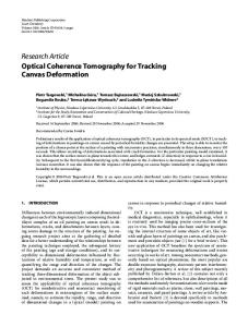
Fig. 1. All steps of the proposed methodology: (a) a two-toned blue screen, (b) the blue screen portion captured by the camera, (c) the resulting frame, (d) its edge-detected counterpart, (e) the grid-lines detected, and (f) the frame rendered using the estimated camera motion parameters.
In a similar way, it has been shown that all other terms in , while the RHS of (22) are of order smaller or equal to . In this sense, and when . VI. SIMULATION AND DISCUSSION In this section, both simulated and natural experiments have been included to verify the efficiency of the proposed approach. In the simulated experiments, a blue screen plane has been constructed in a virtual environment using an appropriate commercial software package. A virtual camera is utilized to render blue screen’s portions, for known camera motion parameters, that is rotation axis and angle, 3-D translation and focal length. On the basis of the captured sequence, camera motion is estimated along the lines of the proposed algorithm and the obtained estimates are compared to the true ones. The two tones of blue (gray) appearing in the illustrations are only indicative, in the sense that they were chosen to be visually distinguishable. For the experiments carried out, a blue screen has been constructed, along the lines of Section III. Assume that a cm cm blue screen wall of physical dimensions horizontal lengths) is available (corresponding to vertical in the particular studio. Assume also that at least one seventh of the blue screen along the vertical dimension is supposed to
be within the camera’s field of view, i.e., approximately 50 cm. By determining block side to be 10 cm, blocks are visible along the vertical dimension out of blocks, which in turn are rounded to to fit the wall’s vertical length. Assuming that one fifteenth of the horizontal dimension is visible to the camera, i.e., approximately 35 cm, and determining the horizontal block side to be 12 cm, blocks are visible along the horizontal dimension. As can be explained in Section III, a large number of blocks incorporated in the dimension treated second (in this case, blocks). However, the number of blocks is limited by the horizontal length of the screen, blocks. Generally, the minimum imposing portion of the wall supposed to be visible by the camera should be chosen sufficiently small, since the blue screen is constructed once, and should serve for general purpose shots. In addition, intuitively, the horizontal visible portion should be generally chosen smaller than the vertical one, since occlusion is expected to be larger. In our case, we result to a minimum blocks, uniquely identified in a portion of blocks. binary matrix of size By construction, known 3-D structure parameters in the reference scene are stored, with respect to Section IV, as (i) the set of ‘vertical’ lines , (ii) the set of ‘horizontal’ lines
XIROUHAKIS et al.: EFFICIENT OPTICAL CAMERA TRACKING IN VIRTUAL SETS
Fig. 2.
619
(a) Captured frame with some grid lines absent and (b) the grid-lines detected.
, . In fact, vertical and (iii) the blue screen 3-D depth and horizontal lines, as well as 3-D depth are determined on the basis of the supposed reference scene. In Fig. 1(a), the constructed (virtual) blue screen is depicted. For an arbitrary camera movement in 3-D space, e.g., for rotaand axis , for transtion angle and scale , the camera caplation tures the blue screen portion depicted in Fig. 1(c). In this particnoninterlaced ular experiment, the camera captured color images with aspect ratio equal to 1. After performing an edge detection step using the Sobel operator, the binary map depicted in Fig. 1(d) is derived. The lines detected by the Hough look-up table, are iltransform module, using a lustrated in Fig. 1(e). The obtained lines were next fed to the camera motion estimation algorithm and the scale and rotation parameters were directly derived w.r.t. Propositions 5 and 2, reand for rotation angle spectively; for scale and axis . As it can be deduced, the obtained parameters are remarkably close to the true ones. By observing Fig. 1(d) and (e), it can be seen that the absence of large contours results in the detection of all grid lines in the captured frame, which is in fact the usual case (see below for the case of absent grid lines). In this sense, the submatrix of corresponding to the visible blue screen portion can be straightforwardly extracted. In fact, as explained above, even a submatrix of would be sufficient to uniquely localize the portion onto the blue screen. The localization of matrix in the binary matrix, allows the establishment of correspondence between the initial 3-D lines and the 2-D lines extracted. Once correspondence is established, Proposition 4 yields the 3-D translation .Inordertovisuallyverifythe vector efficiency of the proposed method, the frame of Fig. 1(c) is re-rendered using the obtained camera motion estimates. In this sense, the frame of Fig. 1(f) should be directly compared to that of 1(c). By comparing these figures, it can be pointed out that the scene rendered by another virtual camera, using the estimated motion parameters, would be correctly aligned for compositing.
TABLE II DETECTING ABSENT GRID LINES. ESTIMATED LINE PARAMETERS (STARTING FROM LEFT) AS OUTPUT OF HOUGH TRANSFORM, NORMALIZED BY SCALE AND CCD ACTUAL SIZES, NORMALIZED LINE DISTANCES IN PAIRS COMPUTED FROM PROPOSITION 3
It can be seen in general that appropriate combinations of shifted maximal sequences do not allow large contours of darker or lighter blue to appear on the blue screen. However, in such rare cases, it is Proposition 3 that ensures that the binary pattern is successfully extracted. Fig. 2(a) illustrates such a captured frame, while the grid lines detected are depicted in Fig. 2(b). By simple observation of Fig. 2(a) and (b), it can be seen that, submatrix, the grid line, abin order to extract a minimum sorbed in the large lighter blue contour, should be detected. In this case, (10) must be utilized to check for all lines extracted in ; note that and are already obtained at this point. Gen(or ) are spatially sorted (which is trivial, erally, lines in since they do not coincide inside a frame), and their distance in pairs is measured using (10). When a distance well exceeds unity, an absent line is detected. In fact, the line itself needs not be detected, since knowledge of its absence is sufficient. Indicative results on detecting absent grid lines are given in Table II. Starting from the left side, columns 1–2 contain line parameters obtained by the Hough transform module, whereas columns 3–4 contain the respective parameters normalized w.r.t. the estimated focal length and the CCD side lengths. The last column depicts normalized line distances in the reference scene, esti-
620
IEEE TRANSACTIONS ON IMAGE PROCESSING, VOL. 10, NO. 4, APRIL 2001
Fig. 3. Natural experiment: (a) the miniature virtual-studio setup, (b) a frame captured by the real-world camera, (c) the edges extracted, and (d) the frame rendered using the estimated camera motion parameters.
mated in terms of Proposition 3. It can be seen, that the normalized distance between lines 4 and 5 (rows 4 and 5 in Table II) is approximately equal to two (row 5 in Table II), which indicates that the pattern row included between lines 4 and 5 should be doubled. Similar results are obtained in the absence of vertical lines. The algorithm’s performance was tested over a number of simulated experiments using different blue screens and arbitrary camera motion parameters. In all experiments carried out, the rotation angle and scale did not vary more than 0.3 and 0.1, respectively. The algorithm’s performance has been tested in a natural environment as well, using the miniaturized virtual set depicted in Fig. 3(a). For the example frame depicted in Fig. 3(b), which was captured by a professional digital camera with a CCD of mm mm and of pixel dimenphysical dimensions , the proposed algorithm was applied in its subsions part indicated by the solid black rectangular border. The corresponding edge detection results are illustrated in Fig. 3(c), while the reconstructed frame, “captured” by a virtual camera
set to the estimated motion parameters, is given in Fig. 3(d). By comparing Fig. 3(b) and (d), one can deduce that the estimated parameters were again remarkably close to the true ones. For the shake of completeness, we include the estimated parameters; (length measurements in millimeters). Finally, it must be pointed out, that the accuracy achieved by the proposed system is only affected by the performance of the Hough transform. In this sense, by using even larger look-up tables, error in motion parameters can be dramatically reduced. The latter is a question of computational power and real-time requirements. VII. CONCLUSIONS AND FURTHER RESEARCH In this work, we proposed a novel system for camera motion tracking in virtual studios on the basis of a two-toned blue screen. A novel methodology for the construction of the blue screen and its binary map has been developed, taking advantage of primitive polynomials and their properties. The pro-
XIROUHAKIS et al.: EFFICIENT OPTICAL CAMERA TRACKING IN VIRTUAL SETS
posed blue screen, along with an efficient method for camera motion estimation from 3-D-to-2-D line correspondences, also proposed, are proved to yield robust motion estimates for successful image/video compositing. The main contributions of this work are both the methodology for the construction of the blue screen and the camera motion estimation method proposed. As far as the former is concerned, it is a flexible option to heuristically constructed blue screens, which can meet the needs of any virtual studio. Regarding the camera motion estimation method, it succeeds in estimating all motion parameters, including the scale (camera focus). Above all, the proposed method eliminates the need of camera calibration, since all measurements refer to a virtual reference scene, and relative camera motion can be reliably extracted. The results presented in this work provide the ground for further improvements in the following manners: 1) efficient extraction of camera motion in degenerate cases, for example when motion or defocus blur is present in the captured sequence or when the perspective projection model is reduced to the orthographic one; 2) effective interpolation between successive frames to reduce computational cost as well as for smoothing purposes; 3) exploitation of the extracted parameters along with the measured defocus, to estimate the actors’ distance from the blue screen (see, for example, Shape From Focus methods [1]). These prospects are currently under investigation. In addition, the testing and the possible incorporation of the proposed method in real virtual set environments is planned in the framework of future development activities.
621
[9] M. Hoetter, “Differential estimation of the global motion parameters zoom and pan,” Signal Process., vol. 16, no. 3, pp. 249–265, 1989. [10] T. S. Huang and A. N. Netravali, “Motion and structure from feature correspondences: A review,” Proc. IEEE, vol. 82, pp. 252–269, 1994. [11] D. Hughes, “Virtual-studio-ultimatte 8,” in IRT Symp. Virtual Studio Technique, Munich, Germany, 1996. [12] Y. Liu, T. S. Huang, and O. D. Faugeras, “Determination of camera location from 2-D to 3-D line and point correspondences,” IEEE Trans. Pattern Anal. Machine Intell., vol. 12, pp. 28–37, Jan. 1990. [13] J. M. Mendel, “Tutorial in higher order statistics (spectra) in signal processing and system theory. Theoretical results and some applications,” Proc. IEEE, vol. 79, pp. 278–305, 1991. [14] L. Quan and T. Kanade, “Affine structure from line correspondences with uncalibrated affine cameras,” IEEE Trans. Pattern Anal. Machine Intell., vol. 19, pp. 834–845, Aug. 1997. [15] L. S. Shapiro, A. Zisserman, and M. Brady, “3-D motion recovery via affine epipolar geometry,” Int. J. Comput. Vis., vol. 16, pp. 147–182, 1995. [16] M. Spetsakis and J. Aloimonos, “Structure from motion using line correspondences,” Int. J. Comput. Vis., vol. 4, pp. 171–183, 1990. [17] M. Tekalp, Digital Video Processing. Englewood Cliffs, NJ: PrenticeHall, 1995. [18] R. Y. Tsai, T. S. Huang, and W. L. Zhu, “Estimating 3-D motion parameters of a rigid planar patch II: Singular value decomposition,” IEEE Trans. Acoust., Speech, Signal Processing, vol. ASSP-30, pp. 525–534, Apr. 1982. [19] J. Weng, T. S. Huang, and N. Ahuja, “Motion and structure from point correspondences with error estimation: Planar surfaces,” IEEE Trans. Signal Processing, vol. 39, pp. 2691–2717, Dec. 1991. [20] Y. Xirouhakis and A. Delopoulos, “Least squares estimation of 3-D shape and motion of rigid objects from their orthographic projections,” IEEE Trans. Pattern Anal. Machine Intell., vol. 22, pp. 393–399, Apr. 2000. [21] Y. Xirouhakis, A. Drosopoulos, and A. Delopoulos, “A novel approach for the estimation of camera motion in virtual studios applications,” in Int. Workshop Synthetic-Natural Hybrid Coding 3-D Imaging (IWSNHC3-DI’99), Santorini, Greece, Sept. 1999. [22] Z. Zhang, “Estimating motion and structure from correspondences of line segments between two perspective images,” IEEE Trans. Pattern Anal. Machine Intell., vol. 17, no. 12, pp. 1129–1139, 1995. [23] [Online] Available: http://www.orad.co.il
ACKNOWLEDGMENT The authors wish to thank the three anonymous reviewers and the Associate Editor for their encouragement in providing erroranalysis results and their guidelines on improving the manuscript overall.
REFERENCES [1] N. Asada, H. Fujiwara, and T. Matsuyama, “Edge and depth from focus,” Int. J. Comput. Vis., vol. 26, no. 2, pp. 153–163, 1998. [2] L. Blonde, M. Buck, R. Galli, W. Niem, Y. Paker, W. Schmidt, and G. Tomas, “A virtual studio for live broadcasting: The Mona Lisa project,” IEEE Multimedia, vol. 3, no. 2, pp. 18–29, 1996. [3] A. Drosopoulos, Y. Xirouhakis, and A. Delopoulos, “An optical camera tracking system for virtual sets applications,” in Proc. Visual, Modeling, Visualization Workshop (VMV’99), Erlangen, Germany, Nov. 1999. [4] O. Faugeras, Three-Dimensional Computer Vision. New York: MIT Press, 1993. [5] R. G. Gallager, Information Theory and Reliable Communication. New York: Wiley, 1968. [6] S. Gibbs, C. Arapis, C. Breiteneder, V. Lalioti, S. Mostafawy, and J. Speier, “Virtual studios: An overview,” IEEE Multimedia, vol. 5, no. 1, pp. 18–35, 1998. [7] S. W. Golomb, Shift Register Sequences. New York: Holden-Day, 1967. [8] M. Hayashi, “Image compositing based on virtual cameras,” IEEE Multimedia, vol. 5, no. 1, pp. 36–48, 1998.
Yiannis S. Xirouhakis was born in Athens, Greece, in 1975. He received the degree in electrical and computer engineering from the National Technical University of Athens (NTUA) in 1997. Currently, he is pursuing the Ph.D. degree in the Image, Video and Multimedia Systems Laboratory, Electrical and Computer Engineering Department, NTUA. His main area of research includes computer vision and video understanding, specifically, 3-D motion and structure estimation, object recognition, and video indexing. Mr. Xirouhakis received several national awards in maths and physics in Greece. He is a member of the Technical chamber of Greece and a student member of the IEEE Signal Processing and Computer Societies.
Athanasios I. Drosopoulos was born in Lamia, Greece, in 1976. He received the degree in computer science from the University of Ioannina, Greece, in 1998. Currently, he is pursuing the Ph.D. degree in the Image, Video and Multimedia Systems Laboratory, Electrical and Computer Engineering Department, National Technical University of Athens. His main research interests include 3-D shape and motion estimation, nonrigid motion estimation, video coding, and artificial neural networks.
622
Anastasios N. Delopoulos (S’88–M’89) was born in Athens, Greece, in 1964. He graduated from the Department of Electrical Engineering, National Technical University of Athens (NTUA) in 1987, and received the M.Sc. degree in electrical engineering from the University of Virginia, Charlottesville, in 1990 and the Ph.D. degree in electrical and computer engineering from the NTUA in 1993. Since 1995, he has been a Researcher with the Institute of Communications and Computer Systems, NTUA. His current research interests lie in the areas of system identification, video coding, multimedia, massively parallel architectures, and biomedical engineering. He is author of 40 journal and conference scientific papers. He has participated in 14 European and National R&D projects mainly related to the application of signal, image and video analysis, and processing to the entertainment, culture, education and health sectors. Dr. Delopoulos is a member of the Technical Chamber of Greece and the IEEE Signal Processing and Computer Science Societies.
IEEE TRANSACTIONS ON IMAGE PROCESSING, VOL. 10, NO. 4, APRIL 2001