VOL. 11, NO. 6, MARCH 2016
ISSN 1819-6608
ARPN Journal of Engineering and Applied Sciences ©2006-2016 Asian Research Publishing Network (ARPN). All rights reserved.
www.arpnjournals.com
EFFECT OF AIR GAP IN THE PERFORMANCE OF AGMD SYSTEM Mohammad Jabed Perves Bappy, Rubina Bahar and Tasnim Firdaus Ariff Department of Manufacturing and Materials Engineering, Kulliyyah of Engineering, International Islamic University Malaysia, Malaysia E-Mail:
[email protected]
ABSTRACT Air Gap Membrane distillation (AGMD) is a prominent technology in the field of water treatment and desalination which is facing a lot of challenges to efficiently produce pure water supply. The system works under the principle of partial pressure difference created between a hydrophobic membrane and a coolant plate by varying temperature on both sides. The membrane and the coolant plate are separated by a thin air gap. Impure hot water flows over the membrane and the evaporated vapour is allowed to pass through the hydrophobic membrane only. Later this vapour condensed on the coolant plate and the pre distilled water is collected. Among the various factors affecting the performance of AGMD system, width of the air gap is the major one to consider. The target of this article is to understand the effect of air gap in AGMD system which will help to build an efficient AGMD water supply system in future using appropriate air gap. In this paper, heat and mass transfer process through the air gap has been discussed for AGMD and a numerical investigation was performed using ANSYS Fluent 15.0 software package and compared with previous experimental results. The investigation shows that distillate flux increased with the decrease of air gap width where the highest 96% of increase of distillate flux found when the air gap is decreased 2.5mm. Keywords: air gap membrane distillation, membrane distillation, freshwater production, simulation, numerical analysis, ANSYS fluent.
INTRODUCTION Membrane distillation is a technique widely used for the last few decades as an energy efficient process of purifying water from aqueous solutions. In this process, hydrophobic membrane is used to separate vapour from liquid by creating temperature difference which produce the partial pressure difference across the membrane and the vapour get condensed to produce distilled water [1-3]. The water vapour coming out of the membrane can be collected in four different ways. In the first one, which is called direct contact membrane distillation (DCMD), the vapour is condensed directly in a cold distilled water stream which flows directly toughing the surface of the membrane [4]. In the second one, Sweeping gas membrane distillation (SGMD), the vapour is collected by a flow of inert gas sweeping by the side of the membrane’s surface which takes the vapour outside of the module and make it condensed [5]. In Vacuum membrane distillation (VMD) process, the vapour is collected by creating a vacuum in the permeate side of the membrane using a pump [1]. In the last one, Air gap membrane distillation (AGMD), a small air gap is kept between the membrane surface and condensation surface. The vapour travel through the air gap, reach at the condensation surface and get condensed [6]. Air gap membrane distillation (AGMD) is getting more attention recently for its energy efficiency and cheap setup cost. No extra energy is required for the process as the evaporation occurs in ambient pressure. Structural costs also can be minimized for its low pressure operation capability [10]. Also AGMD solves the problem of pollution by leakage in DCMD and have the possibility of efficient internal heat recovery unlike SGMD and VMD. AGMD system also have very low amount of temperature
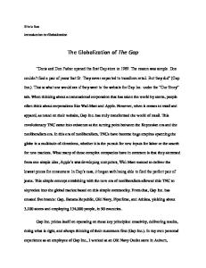
polarization effect and high thermal efficiency compare to other three. Air gap membrane distillation system has a wide range of applications including water treatment, ion separation, desalination, purification etc. AGMD system is used in textile, food, chemical, pharmaceuticals industries as well as in marine platforms [11]. The performance of an AGMD system depends on many factors. The width of air gap has been identified as a major one to consider among them by various researchers in past few decades. In this article an effort has been made to accumulate the findings of various researchers which show the effects of air gap on AGMD system. The heat and mass transfer method through the air gap has been discussed briefly. Also a simulation based numerical analysis is presented to understand the effect of air gap width. The result is compared with the previous experimental result to validate the model. The effect of air gap width on distillate flux is investigated to build a high performance AGMD water supply system in future. WORKING PRINCIPLE OF AGMD The overall system for AGMD is shown in Figure-1. It is seen that the hot fluid side is separated from the coolant side through the membrane, air gap and the coolant plate. Vapour generated on the membrane-hot fluid interface travels through the pores of the hydrophobic membrane , then travels through air gap and gets condensed when comes in contact of the coolant plate. The coolant plate maintains its temperature with the help of cold solution flow over it.
4087
VOL. 11, NO. 6, MARCH 2016
ISSN 1819-6608
ARPN Journal of Engineering and Applied Sciences ©2006-2016 Asian Research Publishing Network (ARPN). All rights reserved.
www.arpnjournals.com HEAT AND MASS TRANSFER THROUGH AIRGAP The transport of vapour through the air gap and membrane pores can be described by molecular diffusion theory. A stagnant air film zone is assumed inside the air gap of AGMD system. The transport of vapour molecules through this stagnant air zone is a laminar flow which occurs for molecular diffusion. The rate of diffusion can be determined by Fick’s Law of diffusion: Nv = -D
Figure-1. Schematic diagram of air gap membrane distillation system. The air gap in AGMD module separates the coolant plate and membrane as shown in Figure-2. In membrane distillation system, the partial pressure difference which occurs due to the temperature difference of the two sides of the hydrophobic membrane causes to evaporate the hot feed water. Inside the air gap of AGMD module, the heat and mass transfer occurs simultaneously. Heat is transferred in diffusion, conduction and convection process. In the case of low air gap the transport process becomes a pure diffusion and conduction process where convection can be ignored. The amount of heat transferred in convection process in very low and can be ignored where the Rayleigh number is high. Condensed water then produces distillate which can be collected from the bottom of the air gap chamber as shown in Figure-2.
� � �
(1)
Where, Nv is the rate of diffusion of vapour molecule through air gap, D is diffusivity, C v is the concentration of vapour and x is the air gap distance. The negative sign arises as the concentration of vapour decreases as the air gap increases. If the air gap is below 5 mm then the flux through the membrane and air gap can be calculated for one directional flow by the equation below [12]: J=
��
���
3.6 +�
��
(2)
Where, Δp is the vapour pressure difference between the membrane feed and the condensation surface. P w is the partial pressure of water. The total mass flow of water vapour through air gap can be calculated by Stefan’s law of molecular diffusion [13]: w, total =
�� � �� ���
(3)
�
Where, A is the area, x is the air gap, D is the diffusion co-efficient. The vapour flow through the air gap also slightly affected by the natural convection in the air gap. The natural convection happens for the temperature difference in the two side of the gap. The importance of the natural convection depends upon the Rayleigh number [14]: Ra =
Figure-2. Air gap in AGMD system.
� �� � 3
(4)
�� �
Where, ΔTx is the temperature difference in the two side of the air gap, δx is the air gap, β is the thermal expansion co-efficient, g is the gravitational acceleration, Va and αa is the kinematic viscosity and thermal diffusivity of air respectively. From the calculation if Ra is found less than 1000 then the natural convection can be neglected compared to conductive heat transfer through the air gap [15]. The conductive heat transfer inside the gap can be expressed as:
4088
VOL. 11, NO. 6, MARCH 2016
ISSN 1819-6608
ARPN Journal of Engineering and Applied Sciences ©2006-2016 Asian Research Publishing Network (ARPN). All rights reserved.
www.arpnjournals.com Q=(
�� � �
+
c) ΔT
et al. [16] tried three different air gap 1mm, 2mm and 3mm with two different tangent flow angle 30̊ and 90̊ and almost 2.5 times more flux achieved when used 1mm gap. From some more other researchers it have been also observed that if the gap can be lessened 5mm to 1mm then almost 2-2.5 times more flux can be achieved [17-19]. In table-1, performance in terms of distillate for various AGMD systems found from previous works are enlisted. From the table it can be observed that the permeate flux is relatively high at low air gap and relatively low at high air gap. Increasing the membrane pore size and feed temperature gives better output but the air gap width remains as one of the dominant factor.
(5)
Where, Ka is the thermal conductivity of air, A is the effective heat transfer area, is the mass flux and ΔT is the temperature difference of the two side of air gap. EFFECT OF AIR GAP WIDTH Various researchers have tried to analyze the effect of air gap in AGMD system by varying it with various other parameters and observing the effect of it. Most of them used PTFE membrane as it is easily available and comes in wide range of pore sizes. R Tian
Table-1. Effect of air gap on various AGMD system.
1-3 1-3 1-5 1-5 1-5 2.5-8.5 2.5-8.5 2.5-8.5 2.5-8.5
60
1.9-9.9
5-2.1
0.2
50
1.62–0.55
5.1–6.3
PVDF
0.22
25.8
1–4
0.8–1.7
NaCl (3.8%)
PTFE
0.2
60
0.3–9
19–1.5
HNO3 (4 M)
PTFE
0.22
80
0.5–2
5.3–4.25
HCl/water
PTFE
0.45
60
4-7
3.7–2.4
Propionic Acid/water
PTFE
0.2
60
4-7
7.4–4.6
Solution type
Membrane type
Membrane pore size (μm)
BL Pangarkar et al. [20]
Seawater Ground water
PTFE PTFE
0.22 0.22
GL Liu et al. [21]
Tap water
FALP
1
MNA Hawlader et al. [22]
Saline water
PVDF
0.45
Artificial seawater
PVDF
0.45
Isopropanol
PTFE
Sucrose
FA Banat et al. [23] MC GarcıaPayo et al. [24] MA IzquierdoGil et al. [25] S Kimura et al. [26] M Matheswaran et al. [27] H Udriot et al. [28]
Feed temperature (̊C) 60 60 55 45 35 60 55 50 45
Permeate Flux (kg/m2hr) 12-6 24-12 22-11 14-7 8-3 4.6-2 3.7-1.5 2.5-1.2 1.8-.8
References
NUMERICAL INVESTIGATION A simulation based numerical analysis was performed using ANSYS Fluent 15.0 software package to understand the effect of air gap in AGMD process and have been compared with the experimental data of Hawlader et al. [22]. ANSYS now supports importing 3D geometry from all popular 3D design software platform. So, the 3D condensation flat plate was designed using Solid Works 3D CAD design module which later imported and calibrated with ANSYS Design Modular. ANSYS software package is selected for its wide range of customizable features. ANSYS and CFX both are gaining popularity recently for its precision and easy operations.
Air Gap (mm)
Although CFX have some limitations in case of3D condensation simulation. The western countries and China are using ANSYS to design 3D CFD model in most of their fields now-a-days. Free student license is also available from this year to increase its collaboration with the wide range of research students around the world. Geometry and meshing The coolant plate is modeled to provide the membrane effective area 88.2cm2 to compare with the experiments of Hawlader et al. [22]. 10cm*10cm*0.5cm plate is used as the condensation plate. Aluminum is selected as the material for its enhanced heat transfer
4089
VOL. 11, NO. 6, MARCH 2016
ISSN 1819-6608
ARPN Journal of Engineering and Applied Sciences ©2006-2016 Asian Research Publishing Network (ARPN). All rights reserved.
www.arpnjournals.com capability. Meshing of the 3D plate is done using ICEM meshing tool which is integrated in ANSYS software package. As meshing is very important to achieve the convergence and maintain the precision of the model. So multiple attempts have been tried to generate high quality grids. After calculation, 25920 numbers of nodes and 165473 elements have been set to the final mesh. Figure-3 and Figure-4 shows the dimension of the model and computational mesh with grids respectively.
Figure-4. Computational mesh. Analysis method and conditions Conditions are set similar to the experiment of Hawlader et al. [22] to perform the simulation. Simulations have been carried out in steady state condition using three dimensional Volume of Fluid (VOF) model. VOF model is selected because it can handle phase change (from liquid to vapour) easily. 3D computational domain is used activating double precision to investigate the volume fraction of condensate mass on the plate. Boundary conditions are set same as the experiment according to which the cold side temperature is 10 ̊C and the hot feed temperature varies in 45 ̊C, 50 ̊C, 55 ̊C and 60 ̊C. Effective heat and mass inlet area, that is the membrane area, is defined as 88.2 cm2 and water volume flow rate defied as 35 ml/min.cm2 as mentioned in Table2.
Figure-3. Model size.
Table-2. Simulation setups and boundary conditions. Simulation setups Model
Multiphase VOF
Solver type
Pressure based
Time study
Steady state
Viscous model
Laminar
Primary phase
Vapour
Second-ary phase
water
RESULTS From Figure-5, comparing the experimental result of Hawlader et al. [22] it can be seen that at 2.5mm air gap experimental data shows highest 5.2 kg/m2hr permeate flux at 60 ̊C feed temperature where the numerical result shows around 5.8 kg/m2hr flux at the same conditions. With the increased air gap, the permeate flux decrease at the both condition; experimental and simulation. At the width of 8.5mm the average flux
Boundary conditions Hot feed Temperatures 45,50,55,60 (Inlet) ( ̊C) Cold feed temperature 10 (outlet) ( ̊C) Wall temperature ( ̊C) 10 Membrane effective 88.2 area (cm2) Vapour volume flow 35 rate (ml/min.cm2) Number of Iterations
1000
dropped down at average 1.5 kg/m2hr which is not a satisfactory output at all. So, by increasing 5mm width, 2.5mm to 8.5mm, the distillate flux production decreases almost 2.5-3 times. Increase of the feed temperature give better result but still negligible compared to the effect of air gap width.
4090
VOL. 11, NO. 6, MARCH 2016
ISSN 1819-6608
ARPN Journal of Engineering and Applied Sciences ©2006-2016 Asian Research Publishing Network (ARPN). All rights reserved.
www.arpnjournals.com
Flux (kg/m^2hr)
7 6 5 4 3 2 1 40
45
50
55
Feed Temperature (̊C)
Experimental
60
65
100
Distillate Flux Increase (%)
Air gap 2.5mm
80 60 40 20 0 45
Numerical
50
Numrical
(a)
55
Feed Temperature ( ̊C )
60
Experimental
Air gap 5mm
6
100
5 4 3 2 1 40
45
50
55
60
Feed Temperature (̊C) Experimental
65
Distillate Flux Increase(%)
Flux (kg/m^2hr)
(a)
80 60 40 20 0 45
Numerical
(b)
50
55
Feed Temperature ( ̊C ) Numerical
60
Experimental
Flux (kg/m^2hr)
(b)
Air gap 8.5mm
5,5
Figure-6. Increase of distillate flux for changing air gaps (a) decrease from 5mm to 2.5mm (b) decrease from 8.5mm to 5mm.
4,5 3,5 2,5 1,5 0,5 40
45
50
55
60
Feed Temperature (̊C)
Experimental
65
Numerical
(c) Figure-5. Feed temperature vs permeate flux comparison between experimental [22] and numerical results for (a) 2.5mm air gap (b) 5mm air gap and (c) 8.5mm air gap [coolant temperature 10 °C]. From Figure-6, at 45̊ C feed temperature the numerical result shows 80% of flux increase when the air gap is decreased 5mm to 2.5mm whereas the experimental result shows 66.67% flux increase in same condition. At 60̊C temperature numerical and experimental result shows around 96% and 61% flux increase respectively (Figure-6a). Similarly, when air gap is decreased from 8.5mm to 5mm (Figure-6-b), then at 45̊ C temperature numerical and experimental result shows 25% and 20% flux increase respectively. At highest 60̊ C they shows 46% and 20% increase of flux at the same condition respectively.
CONCLUSIONS AGMD is making its progress in freshwater production due to low energy requirement and easy maintenance. In this paper the effect of the width of air gap in AGMD system has been discussed and found that it is a very important factor to consider when to design an AGMD system. Permeate flux subsequently increase with the decrease of air gap. 1-2.5 mm air gap gives very high amount of flux when more than 5mm air gap gives very poor result in small scale AGMD module. ACKNOWLEDGEMENT The work was jointly supported by Fundamental Research Grant Scheme (FRGS-14-118-0359) and IIUM Endowment fund (EDW B14-134-1019) by providing necessary financial and technical assistance for this project. REFERENCES [1] Lawson, K.W. and D.R. Lloyd, Membrane distillation. Journal of membrane Science, 1997. 124(1): p. 1-25.
4091
VOL. 11, NO. 6, MARCH 2016
ISSN 1819-6608
ARPN Journal of Engineering and Applied Sciences ©2006-2016 Asian Research Publishing Network (ARPN). All rights reserved.
www.arpnjournals.com [2] Khayet, M., Membranes and theoretical modeling of membrane distillation: A review. Advances in colloid and interface science, 2011. 164(1): p. 56-88. [3] Lee, C.H. and W.H. Hong, Effect of operating variables on the flux and selectivity in sweep gas membrane distillation for dilute aqueous isopropanol. Journal of Membrane Science, 2001. 188(1): p. 79-86. [4] Hsu, S., K. Cheng, and J.-S. Chiou, Seawater desalination by direct contact membrane distillation. Desalination, 2002. 143(3): p. 279-287. [5] Khayet, M., P. Godino, and J.I. Mengual, Nature of flow on sweeping gas membrane distillation. Journal of membrane science, 2000. 170(2): p. 243-255. [6] Alklaibi, A. and N. Lior, Transport analysis of air-gap membrane distillation. Journal of membrane science, 2005. 255(1): p. 239-253.
Prandtl number fluids. Journal of Heat Transfer, 1969. 91(3): p. 391-401. [16] Tian, R., et al., A new enhancement technique on air gap membrane distillation. Desalination, 2014. 332(1): p. 52-59. [17] Zhu, C., et al., Ultrasonic stimulation on enhancement of air gap membrane distillation. Journal of membrane science, 1999. 161(1): p. 85-93. [18] Nene, S., et al., Membrane distillation for the concentration of raw cane-sugar syrup and membrane clarified sugarcane juice. Desalination, 2002. 147(1): pp. 157-160. [19] Alklaibi, A. and N. Lior, Membrane-distillation desalination: status and potential. Desalination, 2005. 171(2): p. 111-131.
[7] Asim, M., Experimental Analysis of Integrated System of Membrane Distillation for pure water with solar domestic hot water. 2013.
[20] Pangarkar, B.L. and M. Sane, Performance of air gap membrane distillation for desalination of ground water and seawater. World Academy of Science, Engineering, and Technology, 2011. 75.
[8] Abu-Zeid, M.A.E.-R., et al., A comprehensive review of vacuum membrane distillation technique. Desalination, 2015. 356: p. 1-14.
[21] Liu, G., et al., Theoretical and experimental studies on air gap membrane distillation. Heat and mass transfer, 1998. 34(4): p. 329-335.
[9] Gálvez, J.B., L. García-Rodríguez, and I. MartínMateos, Seawater desalination by an innovative solarpowered membrane distillation system: the MEDESOL project. Desalination, 2009. 246(1): p. 567-576.
[22] Hawlader, M.N.A., et al., Transport analysis of an air gap membrane distillation (AGMD) process. Desalination and Water treatment, 2012. 42(1-3): p. 333-346.
[10] Carlsson, L., The new generation in sea water desalination SU membrane distillation system. Desalination, 1983. 45(2): p. 221-222. [11] Khayet, M. and T. Matsuura, Membrane distillation: principles and applications. 2011: Elsevier. [12] Kurokawa, H., et al., Vapor permeate characteristics of membrane distillation. Separation Science and Technology, 1990. 25(13-15): p. 1349-1359. [13] Holman, J.P., Heat transfer. Fifth edition ed. 2002: McGraw-Hill, Newyork. [14] Mills, A.F., Basic heat and mass transfer. Second Edition ed. 1999, New Jersey: Prentice Hall [15] MacGregor, R. and A.F. Emery, Free convection through vertical plane layers-moderate and high
[23] Banat, F.A. and J. Simandl, Desalination by membrane distillation: a parametric study. 1998. [24] Garcıa-Payo, M., M.A. Izquierdo-Gil, and C. Fernández-Pineda, Air gap membrane distillation of aqueous alcohol solutions. Journal of Membrane Science, 2000. 169(1): p. 61-80. [25] Izquierdo-Gil, M., M. Garcıa-Payo and C. FernándezPineda, Air gap membrane distillation of sucrose aqueous solutions. Journal of membrane science, 1999. 155(2): p. 291-307. [26] Kimura, S., S.-I. Nakao and S.-I. Shimatani, Transport phenomena in membrane distillation. Journal of membrane science, 1987. 33(3): p. 285-298. [27] Matheswaran, M., et al., Factors affecting flux and water separation performance in air gap membrane
4092
VOL. 11, NO. 6, MARCH 2016
ISSN 1819-6608
ARPN Journal of Engineering and Applied Sciences ©2006-2016 Asian Research Publishing Network (ARPN). All rights reserved.
www.arpnjournals.com distillation. Journal of Industrial and Engineering Chemistry-Seoul-, 2007. 13(6): p. 965. [28] Udriot, H., A. Araque, and U. Von Stockar, Azeotropic mixtures may be broken by membrane distillation. The Chemical Engineering Journal and the Biochemical Engineering Journal, 1994. 54(2): p. 87-93.
4093