EasyPS2000 Software User‘s Guide
Technical requirements • PC with at least 2GHz, 2GB RAM, USB port(s) with USB1.1 or higher • Windows XP OS or newer • Power supply unit PS 2000 B • Unrestricted Windows user permissions • EasyPS2000 software version 2.04
Table of contents 1. Preamble............................................................................................................................ 32 2. Driver installation............................................................................................................... 32 2.1 Trouble-shooting driver installation problems............................................................... 33 3. EasyPS2000 software installation...................................................................................... 34 4. Introduction........................................................................................................................ 35 4.1 Start.............................................................................................................................. 35 4.2 How to purchase a license code................................................................................... 39 4.3 Entering the license code............................................................................................. 39 4.4 Selecting a view mode.................................................................................................. 40 4.5 The menu..................................................................................................................... 42 4.6 Options......................................................................................................................... 43 5. Operation and handling...................................................................................................... 48 5.1 Sequencing and logging............................................................................................... 48 5.1.1 Details about the log file....................................................................................... 49 5.1.2 Details about the sequence file for single output models (Single)........................ 50 5.1.3 Details about the sequence file for double output models (Triple)....................... 51 5.2 Visualisation.................................................................................................................. 52 5.2.1 Introduction........................................................................................................... 52 5.2.2 Other functions..................................................................................................... 53 5.3 The application log....................................................................................................... 55 6. Firmware update................................................................................................................ 56 7. Trouble-shooting................................................................................................................ 56
1.
Preamble
The EasyPS2000 software has been developed in order to remotely control and monitor PS 2000 B devices. It also offers functions to log data from the device or to run automated sequences in form of tables. The user can control only 1 unit with the software. In case there are several units connected to the PC, the user has to select one of them.
2.
Driver installation
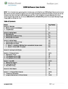
Connect the unit to the PC via the included USB cable. Take care of fitting the mini USB plug correctly and tightly into the socket on the front (might require some force to push it in completely). If the cable is too short for the final placement of the unit, it can be extended by another USB cable (max. 5m) or an USB hub. Windows installs the driver once for every PS 2000 B that is new to the system. In case the driver is not already present on the system, it has to be installed once. Windows should try to find and install the driver like this:
Figure 1
Always select the lowermost option here (Windows XP/Vista/7). In the next dialogue windows you are requested to point to the driver, which is located on the included CD in folder \driver. The correct installation of driver and device can be verified by opening the device manager and looking for in section „Ports (COM & LPT)“. COM8 as well as the name are just an example. If multiple units are connected to the PC, there should be multiple entries here.
2.1 Trouble-shooting driver installation problems When connecting a new device to the PC and if the driver is not already installed on the system, Windows should ask for a driver. In case it does not, the failed driver installation is reported by Windows. In this case you need to open the Windows device manager: XP: Start (or desktop) Right-click „Computer“ Properties Tab „Hardware“ Button „Device manager“ Vista / Windows 7: Start (or desktop) à Right-click „Computer“ à Properties à Link „Device manager“ or type „device manager“ in the search bar and select it from the result list In the section „Other devices“ you should see the device to install, like for example:
Then right-click the entry and select „Update Driver Software“. The well-known Windows driver installation dialogue will appear. Select the lowermost option (example is from Windows 7, Vista and XP are similar):
Figure 2
In the next window select the path to the driver on the EasyPS2000 CD:
Figure 3
Windows will then install the device. After a successful installation the device can be found as „PS2000 Single“ in the device manager, in section „Ports (COM & LPT)“. Note: The COM port number 8 above is only an example. Windows assigns a new COM port for every new device of this type that is installed in the system. The port is remembered and used again if the device is connected the next time. Note: In case there are multiple units connected to the PC, they will all be listed as single devices in the device manager.
3.
EasyPS2000 software installation
To install the EasyPS200 software, double-click the file „setup.exe“ in the folder \install of the included install CD. You will be guided through the installation process. Note: the installer installs a „LabView Runtime Engine“, which is required for the software to run and which requests you to accept two EULAs. Furthermore, there are services installed which are related to the runtime engine. Those services are not required to be running when using EasyPS2000, so they can be set to „deactivated“ or „manual“ in the Windows services console. The installation requires to restart Windows, because a new font „7 Segment“ is installed. If the font or a similar one with the same name is already on the system, it is not replaced by the installation. Then it may come to display errors like this:
Figure 4
To circumvent this problem, any existing font „7 Segment“ has to be deleted from the system. In order to do this, open the font list window in Start à Control panel à Fonts and find font „7 Segment“ in the list. Then right-click and select „Delete“. Note: in Windows 7 the fonts may appear in grouped view, if multiple styles of one font are installed. It means, all versions of the font have to deleted. After this repeat the installation of EasyPS2000.
4.
Introduction
4.1 Start After a successful installation and a restart of the PC, the software can be started from the Windows start menu in Start à All Programs à EasySoft à EasyPS2000. Start logo:
Figure 5
During the start the software will scan for connected PS2000 units:
Figure 6
Once the scan is finished, one of the following results may appear: •
No PS 2000 B detected
Figure 7
In case no unit was detected, please check if the PS2000 unit is properly connected to the PC (USB cable plugged correctly), if the driver is installed completely and if the device is listed in the device manager: Windows XP: Start (or desktop) Right-click „Computer“ Properties Tab „Hardware“ Button „Device manager“ Windows Vista / Windows 7: Start (or desktop) à Right-click „Computer“ à Properties à Link „Device manager“ or type „device manager“ in the search bar and select it from the result list
•
One PS 2000 B detected (not licensed)
Figure 8
Note: if only one unit PS 2000 B is connected and the unit is already unlocked for the software, i.e. status is licensed, this screen is skipped automatically. Otherwise, when showing status „Not licensed“, the device has to be unlocked once by a license code which can be purchased as an option. See section „4.3 Entering the license code“.
•
Multiple PS 2000 B detected
Figure 9
If multiple units have been detected (two in the example above), the user has to select one of them by clicking the corresponding row and confirming the selection with the SUBMIT button. As long as the selected device is not licensed yet, submitting it will open the licensing dialogue first. In this dialogue you can enter the license code which belongs to the particular device and unlock the unit in the software. After it was successfully licensed, EasyPS2000 will automatically enter the normal control GUI. See sections „4.2 How to purchase a license code“ and „4.3 Entering the license code“ for details.
4.2 How to purchase a license code A license code can be purchased seperately and upon request to the local distributor or hardware manufacturer and only requires to report the device‘s serial number (by mail or phone). The serial can be either found on the type plate on the rear of the device or in the device information window in EasyPS2000. In order to show the device information of a device you can use the list of detected devices that is shown after a scan (figure 10). Select the particular device and from the menu „Device“ choose „Information“ or press Ctrl+i.
4.3 Entering the license code Before use, every unit has once to be unlocked for the software. The license is permanently stored on the Windows system. It means, that a reinstallation of Windows requires to unlock any formerly licensed unit again. The same applies, if a unit is going to be controlled by a different PC. Unlocking a device requires a license code, which is tied to the device and which has to be purchased seperately. If the software detects a device which is not licensed already, it will be listed with status „Not licensed“ after a scan.
Figure 10
In order to unlock the device, it has to be selected in the list of detected devices (see Figure 10) and by hitting the button Submit the license dialogue will open:
Figure 11
After entering the license code in field „License code“ check the code with
.
Attention! Mind the case sensitivity and also enter the hyphens! If the code is valid, it will be stated in the status box of the window and the unit is then unlocked. The window will automatically close after 3 seconds and change to the normal control GUI. If the entered code is not correct, an appropriate message is given. Please check carefully if the code really belongs to the device and if all numbers and letters have been entered correctly and if all hyphens are included.
4.4 Selecting a view mode You can select from three different control GUI views:
Select those views from the menu „View“. The views Standard and Compact show a graphical user interface, which corresponds to the front view of the device. The control elements (buttons, knobs) have the same function as the ones on the device. The little USB plug, depicted on the position of the USB socket, can additionally be used to switch between manual and remote control of the device. The lastly selected view mode is stored for the next start. Details about the views by examples from the GUI as shown when using device with single output: • Standard view
Figure 12
This view is the standard view after the installation of the application. Besides the device front, it has additional input boxes to enter the set values U set (voltage), I set (current), OVP set (overvoltage protection threshold) and OCP (overcurrent protection threshold) set directly, plus two buttons. Button: Set remote/ Set local switches remotely between manual and remote control Button: Set output on/off switches the device DC output remotely on/off1 1
only accessible when remote control is activated
• Compact view
Figure 13
View mode „Compact“ is completely for use with the mouse, like when manually operating the device. Changeover between manual and remote control is here done on the small USB plug graphic. • Extended view
Figure 14
View mode „Extended“ shows all values and the device status as text and numbers.
4.5 The menu • View Selects between different views of the GUI. Also see „4.4 Selecting a view mode“. • Device Menu item Device has two subitems: ▪▪ Information Opens a window that shows device related information of the currently controlled or selected device. ▪▪ Scan Scans for connected PS 2000 B units and lists them, as long as multiple units have been detected or if the only connected unit is not licensed. Also see „4.1 Start“. • Options Opens a windows for general settings for data logging, sequencing, visualisation and program log. Also see „4.6 Options“. • Actions In this menu item, the software distinguishes if the controlled device is a model with single output or triple output. The menu entries for Triple models are in brackets below. ▪▪ Sequencing/Logging Opens the sequencing and logging windows. See „5.1 Sequencing and logging“. ▪▪ View/edit sequence file Opens the sequence file, which has been selected in the options, in the assigned application for viewing (eg. Excel or OpenOffice Calc) ▪▪ View log file (View log file output 1 / View log file output 2) Opens the corresponding data log file, which has been defined in the options, in the assigned application for viewing (eg. Excel or OpenOffice Calc) ▪▪ Graph (Graph output 1 / Graph output 2) Opens the window or windows for the graphical visualisation of the output values of the corresponding output. • Help ▪▪ Help file EN Opens this user‘s guide ▪▪ About Shows information about EasyPS2000 and contact details of the software issuer ▪▪ Update device Starts a dialogue to update the device‘s firmware. Also see „6. Firmware update“ ▪▪ View application log file Opens the program‘s log file, which has been defined in the options, in the assigned application for viewing (eg. Excel or OpenOffice Calc) • Exit
Exits the software
4.6 Options Menu item „Options“ is used to do settings for the application, the data logging, the sequencing and the visualisation (graph). • Logging options Settings for data logging feature. For PS 2000 B models with two main outputs, logging is seperate for each output.
Figure 15
▪▪
Log file path Button New opens a „Save as...“ dialogue in order to create a new log file. The log file is then used to write log data. The data in the log is either overwritten as soon as the next logging is started or it is attached to the end, depending on the selected log file action (see below). Button Open opens an existing file for either overwriting or attaching of data. Note: the log file is created as a so-called CSV file, where data entries are seperated by semicolons. One file will contain a maximum of 65450 rows of log data in order to maintain compatibility to MS Excel. In case logging exceeds that number, a new log file is created, which will have a counter like _001, _002 etc. added to the file name. The last log file created by that rule is then used as next log file in the options.
▪▪
Log file name Only shows the log file name.
▪▪
Log interval Defines the interval to write log data into the log file. Minimum: 0.5s Step width: 0.5s Default setting: 0.5s The log interval input box uses the time format 00:00:00,0, which means HH:MM:SS,MS. If entering, for example, 00:00:00,5 this will result in 0.5s log interval or with 00:10 it will be 10 minutes or if just entering 1 it will be 1 hour.
▪▪
Start logging automatically with sequencing Defines, if data logging is automatically started together with the start of sequencing. The file, as selected in options, will be written according to the log file action setting. If no log file is selected, logging won‘t start. Default setting: deactivated. Important: in order to start logging automatically, a log file has to be selected in the Options.
▪▪
Stop logging automatically with sequencing Defines, if data logging is automatically stopped at the end or manual stop of sequencing. Default setting: deactivated.
▪▪
Stop logging on errors Defines if the data logging shall stop automatically when errors like overtemperature occur. If the option is not activated, the log file will record the error in every log data row as long as it is persistent and logging is running. Default setting: deactivated.
▪▪
Log file action Defines, how the log file, which was selected by the buttons „New“ or „Open“ above in „Log file path, is handled: Overwrite Overwrites old log data in the selected log file everytime logging is started.
Attention!! Old log data is deleted without further notice!
Attach
Attaches data of the next logging to former data in the selected log file. If the number of logged data rows exceeds the limit of 65450 per log file, a new log file is created with a name extension like _001, _002 etc., in order to uninterruptedly continue to log data. The last file created from that rule is then used in the options in „Log file name“ and will automatically be used for next logging and with the selected log file action.
Default setting: Overwrite
• Sequencing options
Figure 16
▪▪
Sequence file path Shows the path of the selected sequence file or selects a sequence file with the folder button to the right.
▪▪
Sequence file name Shows the name of the selected sequence file.
▪▪
Sequencing with repetition Defines, if and how often a sequence is repeated. Default settings: deactivated, 1. o Repetitions Repetitions of complete sequence file: 1…65500 = x repetitions
▪▪
Edit sequence file Opens the sequence file, which has been selected in the options, in the assigned application for viewing (eg. Excel or OpenOffice Calc). Note: as long as the selected file is opened in an external software, sequencing can not be started.
• Application
Figure 17
▪▪
Application log file path Defines and shows the path where the application stores its application log file (type CSV), in case the feature is activated with „Save application log“ in the options.
▪▪
Application log file name Only shows the name of the application log file.
▪▪
View Application log file Opens the application log file, which has been defined in the options, in the assigned application for viewing (eg. Excel or OpenOffice Calc).
▪▪
Save application log Defines, if the application shall log events into a seperate log file. Default setting: deactivated.
▪▪
Automatically activate remote control on start Defines, if the selected PS 2000 B is automatically set into remote control mode after a scan or start of the application. Default setting: activated.
▪▪
Restore set values on start Defines, if the program shall store and restore the last set values that were set on the device when the program was terminated normally. The storage of these values is tied to the device serial number, so that changing the PS 2000 B model while the software is not running won‘t restore wrong set values on the device after next start. Default setting: deactivated
• Graph options Settings for graph window. Depending on the device model, i.e. single or triple output, seperate settings for the main outputs are possible here.
Figure 18
▪▪
Time Range Selects the default time range of the graph‘s X axis. The graph window or windows can be opened using the corresponding submenu item in menu „Action“. The time range setting can be changed in the graph windows too, while the graph is stopped, but there the selection is only temporary.
▪▪
Auto-open graph on start If this option is activated, the visualisation window or windows are automatically opened with the application‘s control GUI. Default setting: deactivated.
▪▪
Auto-run graph with logging The visualisation window or windows are automatically opened and the graph(s) will automatically start running if this option activated and logging is started. Default setting: deactivated.
▪▪
Auto-run graph with sequencing The visualisation window or windows are automatically opened and the graph(s) will automatically start running if this option activated and sequencing is started. Default setting: deactivated. Note: if both options „Start logging automatically with sequencing“ and „Autorun graph with logging“ are activated and „Auto-run graph with sequencing is deactivated, the graph(s) will start regardless together with sequencing.
5.
Operation and handling
5.1 Sequencing and logging Sequencing is the step by step processing of a value table, which can control the device almost automatedly. Those tables can be created in MS Excel or OpenOffice Calc or similar, saved as so-called CSV files (seperator: semicolon) and loaded in EasyPS2000. The rows of the table define conditions, which the device shall set for a certain time. The setup of the table is defined as explained below. There is also an example sequence file for each model type, single or triple, in subfolder \data of your EasyPS2000 software installation path. The application will check the format of the table and the given values after a sequence file is selected in the Options window. Errors are reported immediately and point the user to the corresponding column and row. As long as the sequence file is not clear of errors, sequencing can not be started. Note: Sequencing requires the device to be in remote control mode. Logging is the data logging of actual values and device status into a text file of type CSV. The entries are seperated by semicolons and thus the file can be loaded and analysed with table calculation software, such as MS Excel or OpenOffice Calc. Logging is always possible. It means, even if the device is not in remote control and just monitored. In order to maintain compatibility to MS Excel, every log file can only contain a maximum of 65450 logged data rows. If an overflow occurs, a new file is created with a counter in the file name like _001, _002 etc. The window Sequencing/Logging depicts the actual log row with the last actual values and status read from the device, as well as a percental progress bar for sequencing. The progress is related to the number of rows in the sequence file and not to the total time that would result from the times given in every row.
Figure 19. Sequencing / Logging example from a single output model
The „actual log row“ has only informative character. Note: depending on the adjustable log interval, logged values will have a certain skew to the values that are displayed on the device or to those which can be measured at the device‘s output. Example: the device is dynamically loaded with different currents and by logging the current progression shall be recorded. At time x the device had the actual current of 2.52A, which was increased to 3A only 30ms later. If the logged data of the current analysed later on and the log interval would have been set to the minimum of 500ms, the actual current value of 3A would only occur 500ms later in the next row of the log file. In case the current would have been increased even higher within that time, the actual value of 3A would never appear in the log file for subsequent analysis. Thus logging is only practical for less dynamic operations. 5.1.1 Details about the log file If log file and log interval have been selected in the options, data logging from your PS 2000 B device can be started at any time in the Sequencing/Logging window. If you want to view/analyse logged data, use the button „View log file“ in the window „Sequencing/ Logging“ after logging has been stopped. The assigned application for CSV files is then opened. In case none is defined on your system, Windows Notepad will also do, because CSV files are text files. But it is strongly recommended to install a software like MS Excel or OpenOffice Calc. The log file is created like this: Uset 0,00 0,00 0,00
Uactual 1,85 1,85 1,85
Iset 3,00 3,00 3,00
Iactual 0,02 0,02 0,02
Output ON ON ON
Device mode CV CV CV
Error No error No error No error
Date 15.12.2010 15.12.2010 15.12.2010
Time 00:00:00,10 00:00:00,20 00:00:00,30
The first row is only a header, captioning the columns. In a text editor like Notepad, the columns will be seperated by semicolons. Uset - Last set value for output voltage 1 Uactual - Last read actual value of output voltage Iset - Last set value for output current 1 Iactual - Last read actual value of output current Output - Output condition Device mode - Control mode of the unit (CV = Constant Voltage, CC = Constant Current) Error - Errors, that may have occured during logging:
(OV = Overvoltage, OC = Overcurrent, OT = Overtemperature)
Date / Time - Date of the log file entry creation and running time since logging start
1
The value is always read from the device, no matter what was set in the control GUI at last
5.1.2 Details about the sequence file for single output models (Single) In order to run sequencing, a sequence file has to be selected in tab „Sequencing“ of the options dialogue. Otherwise, sequencing is not accessible. Following is required for Sequencing: •
The device is already in remote control mode
•
The sequence file is correct and accepted by the application
The required format of the sequence file is defined like this:
The first row is only a header, captioning the columns. It is not necessarily required, but if missing, the application would start the sequence by processing from row 2. After selecting a sequence file in the options window, it is immediately checked for correct format and values in the columns C to I. Entries in columns A and B are ignored. Following assignment of the columns (entries in red are absolutely required): Step
- Arbitrary, normally used to count up the sequence steps
Description
- Arbitrary, can be used to describe the step
U set
- Voltage set value without unit, decimal places allowed
Allowed value range: 0 to nominal device voltage
I set
- Current set value without unit, decimal places allowed
Allowed value range: 0 to nominal device current
Note: voltage and current have to match according to formula P = U * I. The application will check the values and calculate the resulting power. If, for example, 40V and 5A would be entered in one row, it would result in a power of 200W. But a PS 2000 B with 42V nominal either has 100W or 160W nominal power. Manually setting 40V and 5A at the same time on the device is also not possible. Output
- Defines, if the DC output shall be ON or OFF for the duration of the row.
In case the entry is not given, the output condition is not altered. Note: with OFF given, the output will be switched off as soon as the row is processed and the output voltage will sink fastly or slowly, depending on the load. When sinking slowly, it may take longer to sink down to the voltage value that is given in the next row than the time for the current row defines. So some time of the next row might be required to let the voltage sink down to the voltage value of the next row, if lower than the one of the previous row. Hour
- Together with columns G to I, it defines the time for the actual row in
format H:M:S,MS. That time has to elapse until the next row is processed.
Allowed value range: 0…24 (integers only)
Minute
- Together with columns F, H und I, it defines the time for the actual row in
format H:M:S,MS. That time has to elapse until the next row is processed.
Allowed value range: 0…59 (integers only)
Second
- Together with columns F, G und I, it defines the time for the actual row in
format H:M:S,MS. That time has to elapse until the next row is processed.
Allowed value range: 0…59 (integers only)
Millisecond
- Together with columns F bis H, it defines the time for the actual row in
format H:M:S,MS. That time has to elapse until the next row is processed. Allowed value range: 0 or 500 Following requirements for the sequence file: • The set values for voltage and current have to be given in every row, even if only the output is switched off • The set values for voltage and current have to be within the nominal values of the device and their product according to P = U * I must not exceed the device‘s nominal power • Minimum time per row: 500ms • Step width: minimum 500ms • Maximum time per row: 24h 59min 59sec 500ms • CSV file format with entries seperated by semicolons 5.1.3 Details about the sequence file for double output models (Triple) The sequence file structure for Triple models is almost the same as for Single models, except here it requires another row „Output select“. This row selects if the values/condition in the row are either sent to output 1, output 2 or both. In case the row selects both outputs, the tracking mode feature is activated for the current row. The required format of the sequence file is defined like this:
Description of row „Output select“: 1 = Values in the row are sent to output 1 only 2 = Values in the row are sent to output 2 only 12 = Values in the row are sent to both output, but with a small skew of a few milliseconds, because tracking mode is activated before the set values are sent Any other value or term in this column will cause the program to send the set values to output 1.
5.2 Visualisation 5.2.1 Introduction Visualisation (or: the graph) is a graphical display of set values and actual values in a temporal progression. The displayed time period (X axis) can be varied between 1 second and 10 minutes in 4 steps, as long as the graph is stopped. The window „Visualisation“ can be accessed via the menu „Actions“ à „Graph“ resp. „Graph output 1“ or „Graph output 2“. The graph is either manually started/stopped or can automatically run if sequencing and/or logging is started (also see sections 4.6 and 5.1). The window can be maximised to have a bigger graph area. Overview:
Figure 20
Explanation of the control elements: ▪▪ ▪▪ ▪▪ ▪▪ ▪▪ ▪▪ ▪▪ ▪▪
Time Range Temporarily selects the time range for the graph‘s X axis. 1s, 10s, 1m or 10m. Start Starts the graphical visualisation Stop Stops the graphical visualisation Reset Resets and clears the graph U set visible Defines, if the plot of the voltage set value is displayed in the graph or not I set visible Defines, if the plot of the current set value is displayed in the graph or not U actual visible Defines, if the plot of the actual voltage is displayed in the graph or not I actual visible Defines, if the plot of the actual current is displayed in the graph or not
5.2.2 Other functions History The graph records up to four plots over time. The recorded data is available in a history, which can be accessed after the graph is stopped. The scrollbar below the X axis can be used to select a section of the recorded history between 0 and end. Sections can be zoomed or saved as image. See below. Screenshots It is possible to save screenshots from the graph‘s history. In order to so, stop the graph, scroll back to the relevant position and right-click into the graphical area and select „Export simple image“. Note: In case the context menu is in german, you need to install a multilanguage version of the „LabView Runtime Engine (RTE)“, which is not included in the installation by default. You can download the RTE from National Instrument (www.ni.com), finding it by entering the keywords „labview rte“ (without the quotation marks) and selecting the proper Windows version from the results. Note: Export of screenshots only works if the graph is stopped. Zoom When using the zoom button
a zoom menu will appear:
Selection zoom
This will zoom a user-defineable selection on the graph area
X axis zoom
Zooms a part of the X axis range (time)
Y axis zoom
Zooms a part of the Y axis range (voltage, current)
Complete history
Zooms out to show the complete graph history at once
Zoom out Zoom in Free hand mode Fix
Move the graphical with the mouse pointer in all directions Exits the free hand mode again
Signal menu
By clicking on the black rectangles next to the signal name, the signal‘s appearance can be changed like line thickness, line type, color etc. Note: screenshot taken from german context. Diagram type Colour Line type Line thickness Anti-Aliasing Bar plots Fill baseline Dotted display X axis Y axis These settings are mostly self-explaining. Note: The settings are not stored and are thus only temporary The frame „Control“ in the graph windows contains additional control elements which can enable or disable the signals shown on the graph. By default, only U actual and I actual are activated.
5.3 The application log The application can record a log about events like actions done or errors. By default, this feature is deactivated. In order to activate it, access the options in tab „Application“. See section 4.6 and fFigure 17 on page 46. To have a view into the log, go to menu „Help“ and select „View application log file“:
The application log file is called ps2_application_steps.csv by default. But you choose a different name in the options dialogue in tab „Application“. Like with the other log file, it is saved as text file in CSV format (entries seperated by semicolons): Step Voltage set to 3,100V. Voltage set to 0,000V. Scanned for PS2000. Voltage set to 0,400V. Voltage set to 6,300V. Voltage set to 17,600V. Voltage set to 26,250V. Voltage set to 42,150V. Voltage set to 49,600V. Voltage set to 59,450V. Voltage set to 71,000V. Voltage set to 80,100V.
Date 13.12.2010 13.12.2010 13.12.2010 13.12.2010 13.12.2010 13.12.2010 13.12.2010 13.12.2010 13.12.2010 13.12.2010 13.12.2010 13.12.2010
Time 12:56:31 12:56:31 12:56:56 12:57:00 12:57:01 12:57:01 12:57:01 12:57:01 12:57:01 12:57:01 12:57:01 12:57:02
6.
Firmware update
A firmware1 update is normally done to implement new or altered feature to your device or to remove bugs. In order to update the firmware of your PS 2000 B, access menu item „Update device“ in menu „Help“. A dialogue will guide you through the update process. Before you can update your device, you need to have a new firmware file, which can either be found on the website of the device manufacturer or the website of your local distributor or upon request.
7.
Trouble-shooting
Problem: The license code is not accepted Solution(s): Enter the license code again and take for case sensitivity and make sure to enter all hyphens. Problem: After successfully entering the license code, the application changes to the normal control GUI, but it is greyed out Solution(s): Scan again for devices with „Device“ -> „Scan“. Problem: The EasyPS2000 GUI is suddenly greyed out and shows „Error“ Solution(s): Check the USB cable, if plugged correctly. Also try to unplug and plug the cable again and repeat the scan. Alternatively, check the Windows device manager if it lists the device in section „Ports...“. Problem: After switching the device on, it permanently shows „PS 2000“ Solution(s): Switch device off and on again. Alternatively, remove the USB cable before switching the device on again and plug it later again. Problem: EasyPS2000 can not detect my device resp. I connected multiple units and one or more of them are not listed Solution(s): Remove USB cable, plug again and repeat scan à if still not found, check the Windows device manager à if the unit(s) does not appear in section „Ports...“, then the driver is not installed correctly or missing or the USB socket is broken à repeat driver installation (see section „2.1 Trouble-shooting driver installation problems“) Problem: EasyPS2000 was closed, but the device is not manually accessible and still shows „Remote“ Solution(s): Switch device off and on again.
1
Firmware = software for device like a power supply
Problem: In „Standard“ view it does not show the lower control elements anymore Solution(s): Exit the application, open Windows Explorer and go to the installation folder of EasyPS2000, change to subfolder \data and delete the file „ps2000.ini“ and restart the application. Attention! This will reset all settings in the options window to defaults Note: Avoid resizing the main window on the window edge. Maximising is allowed and done with the typical Windows maximise button.