Durability Assessment of Heavy Duty Diesel Engine Cylinder Head A.H. Guzel, S.Erpolat, O. Cicekdag Ford Otosan A.Ş, Turkey Abstract: The recent heavy duty truck market towards higher power output, lower fuel consumption and reduced emissions. This trend leads challenges in heavy duty diesel engine design due to increasing thermal loads for hot components. One of the most important design feature for heavy duty diesel engines is cylinder head fatigue durability and gasket sealing performance. Cylinder head is subjected to low cycle thermo-mechanical fatigue (TMF) and highcycle fatigue (HCF) which are driven by combustion process. Gasket sealing performance also has to be considered for avoiding any performance loss resulting from gas leakage. Fatigue life prediction robustness of cylinder heads has reached a high level of confidence past few years; there is still work to increase the reliability of these analyses by improving modeling methodologies and material models. Current study will focus on heavy duty engine cylinder head made of compacted graphite iron development methodology using coupled 3D combustion simulation, conjugate heat transfer and both high cycle fatigue (HCF) and thermo-mechanical fatigue (TMF) analysis methodologies. Also gasket sealing performance is calculated with a proper methodology and it is verified by durability tests.
Keywords: Cylinder Head, High Cycle Fatigue, Thermo-Mechanical Fatigue, Engine Gasket Failure
1. Introduction Heavy duty engine cylinder head is probably the most complex engine component to design. Several conflicting design aspects should be taken into consideration. At an early stage of development of cylinder head port development to meet combustion performance and strict emission legislations is important. Water jacket is designed to meet adequate cooling of the engine structure to stay well below critical metal temperature limits and to achieve optimum thermal efficiency. Gasket selection is crucial, since sealing and distortion requirements against assembly, thermal, and firing loads. Other important aspects are manufacturing constraints, such as minimum wall thickness, porosity, and residual stresses thermal growth has to be taken into consideration. In addition to that, one of the most important design aspect is both low cycle and low cycle fatigue durability A typical cast iron cylinder head reaches a maximum temperature level up to 380°C and sometimes more whereas the minimum temperature could be below –30°C during cold winter climates. The thermo-mechanical fatigue (TMF) of a cylinder head during such a start-stop cycle needs to be considered in engine design. Temperature fluctuations lead to low-cycle fatigue of cylinder head particularly around valve bridge areas, injector holes and glow plugs. 2015 SIMULIA Community Conference www.3ds.com/simulia
1
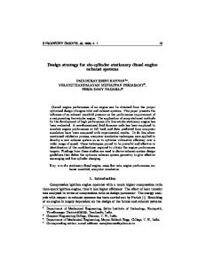
At peak temperature, the cylinder head is also subjected to mechanical loading due to firing pressures. In a modern heavy duty diesel engine, peak firing pressures may reach up to 230 – 240 bar. Therefore, high cycle fatigue (HCF) should be considered in engine design as well. Typical HCF critical regions are fillets of water jacket, particularly those around main bolts and injectors. HCF is a very different phenomenon to TMF and they are usually treated independently. A typical workflow of Ford Otosan (FO) for CAE assessment of cylinder head is shown fig. 1.
Figure 1. Typical workflow for cylinder head durability analysis in FO.
2. Thermo-Mechanical Fatigue Calculation Approach TMF is a very complex phenomenon that is a combination of a number of different mechanisms, such as mechanical fatigue, oxidation, and creep. There are different TMF models currently used at Ford Otosan to evaluate fatigue life of cylinder head based on material. In this paper GJV-450 type compacted graphite iron TMF analysis methodology will be discussed. In general thermo-mechanical fatigue life prediction models consider the interaction between fatigue and creep at varying temperatures. The difficulty in understanding and predicting the interaction behavior has stimulated significant research effort in finding reliable life prediction methodologies. The models can be distinguished between damage based, stress based, strain based, energy (work) based criterion or combined approaches. Physically they are based on e.g. fracture mechanics, microstructural theories or empirical observation. In this paper Z-Set Zebulon Abaqus coupled methodology is given to calculate TMF life by using modified Chaboche approach. This methodology is used at Ford Otosan for heavy duty cylinder head made of GJV450. Z-Set Zebulon Abaqus coupled approach can also utilize dissipated energy based on hysteresis loop by using stress and strain tensor calculation scripts. The basic idea of classical Chaboche [1-2] approach is the summation of the damage caused by different failure mechanisms. Chaboche approach introduces a term called brittle to consider cast iron material behavior. Table 1 illustrates how this general approach is utilized by Chaboche.
2
2015 SIMULIA Community Conference www.3ds.com/simulia
Table 1. Basic equations Standart Chaboche damage model. Damage Summation
Creep + Fatigue Damage
Brittle Damage
Under cyclic loading compacted graphite cast iron’s behavior is specified by a closure region under compressive loading direction with previous tensile loading direction. This has led model to formulate a damage based deformation behavior model for GJV-450 with a core elastoviscoplastic Chaboche type model. This model includes Von Mises type yield criteria, isotropic and kinematic hardening and a Norton flow law. Standard Chaboche model is improved by a damage state variable depending on the maximum principal stresses [3-4].
Figure 2. Damage energy (red area) during cyclic loading It should be noted that current life estimation using Zebulon is actually made by post processing inelastic dissipated energy criterion :
ΔWine Where ΔWine is the inelastic dissipated energy density per cycle determined at stabilized hysteresis loops; A is damage parameter, which is a function of maximum temperature; and α is a material constant. In general energy based methods result in specific damage parameters as well. 2015 SIMULIA Community Conference www.3ds.com/simulia
3
In terms of physics they rely on empirical observations. Although there are many different approaches the basic concept is the same. It is assumed that the work done upon the material by the external forces causes fatigue damage. It includes elastic as well as plastic energy. Graphically the energy represents the area inside stress-strain hysteresis loop (fig. 2).
3. Computational Fluid Dynamics Analysis In Ford Otosan, for the thermal analyses of heavy duty cylinder head structure, conjugate CFD analysis is used. Fig. 3 shows the CFD methodology for cylinder head metal temperature calculation.
Figure 3. Conjugate Heat Transfer Modeling Approach CFD analyses are started from 1D engine model calculations and combustion analysis. The gas dynamics and combustion is solved by Converge CFD code which is a three-dimensional CFD program to simulate moving surfaces of components such as piston and valves at internal combustion engines (ICE) and is capable of solving compressible, chemically reacting, transient, multiphase flows. In conjugate analysis, the model in CFD environment involves both fluid and solid domains and the temperature field of the structure is simultaneously solved with the coolant flow, and hence, eliminates the need to define boundary conditions on the structure-coolant interface at an expense of running times. Star CCM+ is used to perform conjugate CFD analysis, where the solid and fluid domains are meshed with polyhedral elements and conformal mesh is produced on the interface which minimizes the data exchange errors on the interface. Particular attention is paid to evaluate the boiling phenomenon on water jacket interface of flame deck. In order to incorporate boiling effect, Star CCM+’ built-in modules are used. Heat transfer coefficient (HTC) distribution of water jacket and flame deck temperature distribution heavy duty cylinder head’s at peak power condition is shown fig. 4.In order to maximize the cooling efficiency, water jacket is designed top-down cooling type which has two different stratified cooling channel in cylinder head. 4
2015 SIMULIA Community Conference www.3ds.com/simulia
Figure 4. HTC distribution at water jacket & Temperature distribution on a flame deck
5. Finite Element Modeling of Structural Analyses Commercial finite element package Abaqus is used for cylinder head structural analyses. A typical finite element model includes cylinder head, block, main bolts, gasket, valve seats and guides. Valves are usually included in heat transfer analyses. A number of assembly loadings are defined including valve seat, valve guide interferences, cylinder head bolt clamping. Thermal expansion step following assembly loading is based on the temperature distribution obtained from conjugate CFD analysis performed under rated power operating conditions. If it is HCF and gasket sealing analyses, for the final set of loading steps, peak firing pressures are applied into cylinder head, block and valve seats. Global model for cylinder head is shown in fig 5.
Figure 5. Global model for heavy duty cylinder head durability analysis Since TMF material models are computationally expensive for Z-set Zebulon, submodels are used for the assessment of flame deck area. Global cylinder head and submodel is modeled in Abaqus 2015 SIMULIA Community Conference www.3ds.com/simulia
5
and Z-set Zebulon only uses submodel to calculation of TMF life. For HCF and gasket failure analysis ,no need to create submodel. Typical submodel for a heavy duty engine is shown in fig. 6
Figure 6. Submodel of TMF assessment and driven nodes In Abaqus models nonlinear material properties for each component, gasket loading/unloading curve and nonlinear contact definitions-interference between each component are defined.
6. Fatigue Life Post-Processing 6.1
TMF Postprocessing
Heat up and cool down steps are defined as one TMF cycle and a cylinder head must meet a predefined minimum number of TMF cycle as a design criteria. Abaqus –Zebulon coupled approach for TMF life calculation contains five cycles. In heavy duty diesel cylinder heads, critical regions for TMF are valve bridges and injector hole’s flame face region. These regions are subjected to out-of-phase TMF loading (fig.7). During OP-TMF loading, the oxidation mechanism becomes significant, whereas creep damage is negligible, because void growth is suppressed in compression [5]
.
Figure 7. Out-of-phase and In-phase loading in TMF 6
2015 SIMULIA Community Conference www.3ds.com/simulia
Fig. 8 shows TMF life assessment of heavy duty cylinder head at rated power condition. TMF failure is expected around injector hole around 10000 cycles.
Figure 8. Thermo-Mechanical Fatigue Life Result of the most critical cylinder 6.2
HCF Postprocessing
As next study to investigate HCF assessment of a heavy duty cylinder head, same FE model used in the TMF analysis, however HCF analysis procedure is different .Model runs with different loading steps while cylinder pressure is dominant loading condition in HCF failure. Different from TMF analyses, the engine components are heated up to rated power temperatures at steady state condition after assembly loads applied. Peak firing pressure is applied on both cylinder head, cylinder block and valve seat’s gas surfaces as separate steps following engine firing order. Resulted Abaqus stress file is used in FEMFAT Transmax and stress amplitudes, mean stress and constant stress are calculated at each node using scaled normal stress in critical plane method. Surface roughness, range of dispersion and isothermal influences are taken into account calculating local S-N curve at each point. The resulting stress amplitudes are used together with a tension/compression S-N curve for the calculation and linear summation of partial damages according to Miner rule. The plane with maximum damage is assumed to be most critical. Fig. 9 and fig. 10 shows minimum safety factor calculated at different cross section in a heavy duty cylinder head. According to results, the hottest spot is on lower water jacket bottom around intake ports (fig. 10).
2015 SIMULIA Community Conference www.3ds.com/simulia
7
Figure 9. HCF results for top water jacket Min. Fatigue safety factor (FSF) reported at these locations is around 1.2. Hot spots also investigated around exhaust ports shown at fig 7. Minimum FSF calculated at these locations are around 1.18. FSF around bolt columns are also shown.
Figure 10. HCF Results bottom water jacket
7. Gasket Failure Analysis Ford Otosan has developed a methodology that predicts gasket sealing performance and gasket failures between cylinder head and engine block. Methodology is very useful at early selection stage of gaskets. As a final study to investigate the gasket failure assessment of heavy duty cylinder head, again same FE model that is used in TMF and HCF analysis is handled. Number of steps and procedure is same with HCF analysis. However, post-processing methodology is different. Ford Otosan has in-house developed post-processor is used to perform gasket failure analysis .After completed post-processing stage results are compared with test results. Nonlinear gasket behavior curves and special Abaqus gasket elements are used to simulate gasket sealing performance during rated power condition. Both thermal and peak fire pressure applied to the model. Gasket FE model of one of the cylinder is shown in fig. 9. 8
2015 SIMULIA Community Conference www.3ds.com/simulia
Fig. 9: Gasket FE model of one of the cylinder This type of a heavy duty engine generally includes liners for each cylinder. This makes the problem a challenging task. Fig 9 shows a typical heavy duty engine liner, engine block and cylinder head assembly representation. It is important that values of protrusion and recess should be input correctly to the model.
Fig. 9: Representative Liner Positions Abaqus offers gasket modeling approach to overcome modeling issues about assembly of gasket between block and head. Both recess and protrusion can be modeled by defining initial gap selection of Abaqus gasket behavior [6].
2015 SIMULIA Community Conference www.3ds.com/simulia
9
Correlation between Abaqus results and test results are shown in fig 10. Maximum dynamic gap between gasket beads and cylinder head is occurred and reaches the critical value 1.1 times. It can be seen that very good correlation is observed.
Figure 10. Correlation CAE results with test
8. Conclusions Failure of a cylinder head is mainly caused by both high cycle fatigue due to high firing loads and thermo-mechanical failure due to thermal loading cycle during start-stop of an engine. A methodology is developed to predict both of these fatigue failure and another failure mechanism is gasket failure in an engine head based on combination of combustion model, CHT model with both TMF and HCF calculation tools. Future strategies like integration of material inhomogeneity and residual stresses will be implemented into durability analyses. Also component level rig tests to improve both CAE studies and Design Verification (DV) efficiency will be studied.
9. Acknowledgement Authors would like to thank Cengizhan Cengiz and Serdar Guryuva for leading CFD work and Dr. Ronald Foerch for their support in Z-set Zebulon software. The authors wish to express their gratitude Yigit Yazicioglu ,Demirhan Manav and Aidin Dairo to help in developing the TMF and HCF and test methodology.
10. References 1. Chaboche, J.L.: Time-independent constitutive theories for cyclic plasticity. Int. J. Plast. 2, 149-188, 1986 2. Chaboche, J.L.: Constitutive equations for cyclic plasticity and cyclic viscoplasticity. Int. J. Plast. 5, 247-302, 1989 10 2015 SIMULIA Community Conference www.3ds.com/simulia
3. F. Zieher, F. Langmayr, A. Ennemoser, A. Jelatancev, G. Hager, K. Wieser : Advanced Thermal Mechanical Fatigue Life Simulation of Cylinder Heads” , 2004 ABAQUS Users’Conference 4. R. Foerch, F. Zieher, and F. Langmayer “TMF Applications Using a Damage-Based Cast Iron Model”, 2002 ABAQUS Users’ Conference 5. Minichmayr, R.; Riedler, M.; Winter, G.; Leitner, H.; Eichlseder, W.: Thermo-mechanical fatigue life assessment of aluminium components using the damage rate model of Sehitoglu. International Journal of Fatigue, Volume 30, Issue 2, February 2008, Pages 298-304 6. Abaqus Users Manual, Version 6.13-1, Dassault Systémes Simulia Corp., Providence, RI.
2015 SIMULIA Community Conference www.3ds.com/simulia
11