European Heart Journal (1997) 18, 1396-1403
The technique of impedance cardiography H. H. Woltjer, H. J. Bogaard and P. M. J. M. de Vries Department of Pulmonary Medicine, Academic Hospital VU, Amsterdam, The Netherlands
Introduction
Basic principles of impedance cardiography Impedance cardiography is founded on Ohm's law R= VII, where R is resistance (Ohm), V is voltage (volt) and / is current (ampere). Resistance in an alternating current is called impedance (Z) and can also be calculated as Z= VII in impedance cardiography. This law is applied to an electrical model generally used for the human body: the parallel conductor model. This model assumes that the impedance of thoracic tissue is parallel to that of blood. The validity of this assumption has been shown by various investigators'2"41.
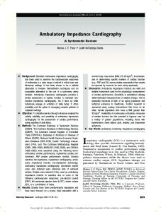
The electrode configuration Cardiac-related impedance changes are measured by passing a sinusoidal current of 50-100 kHz between two electrodes on the thorax and measuring the resulting voltage between two other electrodes. As current strength is known, the impedance can be calculated. The conventional method according to Kubicek et a/.1'1 uses a tetrapolar band electrode configuration (Fig. l(a)). The band electrodes, however, are not practical for use; they are difficult to place in clinical settings'51, uncomfortable to wear and expensive. Therefore, many investigators have tried to replace them with disposable spot electrodes, which would be far more practical. Penny et a/.'61 were the first to replace the band electrode array with four disposable spot electrodes. However, there was a considerable discrepancy between the stroke volume calculations using the Kubicek equation[l). In 1986 Bernstein'71 altered Sramek et al's. newly proposed methodology'81 and proposed a new eight disposable spot electrode array (lateral spot electrode array, Fig. l(b)). This array became very popular; many studies have been performed comparing other techniques of estimating stroke volume with Sramek and Bernstein's method (Table 2). However, Woltjer et al.[9] showed that the original band electrode array and the lateral spot electrode array do not give the same results. Furthermore, it has currently been proven that with the lateral spot array a highly inhomogeneously electrical field is created'101. This implies that values found for baseline thoracic impedance (Zo), necessary for stroke volume calculations, are not comparable between individuals and therefore might affect the validity of the method.
Recently a promising new nine disposable spot electrode array has been proposed by Woltjer et a/.'101 (modified semi-circular array, Fig. l(c)). This array is a Revision submitted 8 July 1997, and accepted 11 July 1997. modification of Bernstein's array'7', but creates a far Correspondence: P. M. J. M. de Vries, Academic Hospital VU, Department of Pulmonary Medicine. P.O. Box 7075. 1007 MB better homogeneous electrical field and is interchangeable with the original band electrode array. Future Amsterdam, The Netherlands. 0195-668X/97/091396+08 S18.00/0
1997 The European Society of Cardiology
Downloaded from http://eurheartj.oxfordjournals.org/ by guest on January 23, 2017
Impedance cardiography has been studied for the past 30 years as a non-invasive, harmless and cost effective method of monitoring stroke volume and other indicators of cardiac function. As a measure of stroke volume it has attracted the most interest. Since impedance cardiography has the potential to supply cardiovascular variables on a beat-to-beat basis, its possible clinical applications are unique, e.g. continuous monitoring of systolic time intervals, stroke volume and systemic vascular resistance, when combined with noninvasive blood pressure measurement. Therefore, such a technique would be very useful in patients with acute myocardial injury and in other critical care settings. In 1966 Kubicek et al.l>] described their method of calculating stroke volume from the thoracic impedance signal. Today, the method has been subjected to various refinements and alterations. In order to establish its validity, impedance cardiography has been extensively compared to several other methods which measure stroke volume in both man and animals. The technique of impedance cardiography, however, has not yet been accepted world wide as a reliable method of assessing cardiac output. In the present review the current status and the various aspects of the impedance methodology are summarized and discussed.
Other than fluctuations caused by respiration thoracic tissue impedance is constant. Blood-related impedance changes repeat themselves with every heart beat and are linked to cardiac activity.
Reviews
I
(a) Band electrode array
(b) LS electrode array
1397
MSC electrode array
research should indicate whether this array can be used for stroke volume measurement.
The impedance signal and its origin A typical impedance signal (dZ), its first derivative (dZ/dt) with marks on the important points of the wave form, and the ECG are shown in Fig. 2. Since Kubicek et al. introduced their methodology for stroke volume calculation, the first derivative of the impedance signal has extensively been studied by many investigators to discover its physiological correlates and origin. Karnegis et a/.1"1 first showed that the A-wave follows the P wave of the ECG, and the C-wave is associated with ventricular contraction. During diastole, they noticed another upward deflection of the dZ/dt signal: the O-wave. Lababidi et alP2] compared the dZldt signal with simultaneously performed phonocardiography in 91 subjects. They found that the B-point coincides with the aortic valve opening and the X-point with aortic valve closure. These observations have been confirmed by several investigators using echocardiography and aortic pressure recordings113'14'. Today the dZldt signal is highly sensitive for systolic time intervals"5-171. The origin of the impedance cardiographic signal appears to be complex and the exact physiological and anatomical basis still needs further explanation. Many investigators have dealt with this subject in the past. In general, evidence to support the origin of the impedance cardiographic signal has been derived from studies, which tried to correlate physiological parameters to the dZldt signal, modelling studies and studies performed in animals. The A-wave Lababidi et a/.[12' and Karnegis et a/.1"1 found convincing evidence that the A-wave is linked to the contraction
dZ/dt
Zero
ECG Figure 2 Characteristic dZ, dZldt and ECG signal, where A is the downward deflection due to the contraction of the atria, B is the start of ejection of blood by the left ventricle, C the major upward deflection occurring during systole, X the closure of the aortic valve, O the diastolic upward deflection, LVET the left ventricular ejection time (s) and dZldtmax the maximal impedance change during systole (Qls).
of the atria. Lamberts et alPS] raised the hypothesis that this wave has its source in the back flow of blood from the atria into the central veins. Takada et al.[l9] found evidence that the left atrium might be the main contributor to this wave. He showed that the left atrial ejection fraction is highly correlated to the relative height of the Eur Heart J, Vol. 18, September 1997
Downloaded from http://eurheartj.oxfordjournals.org/ by guest on January 23, 2017
Figure 1 Illustration of the electrode arrays as frequently used in impedance cardiography, where C are the current injecting electrodes and V the voltage measuring electrodes. The spot electrodes at one horizontal level are always electrically connected. LS=lateral spot; MSC=modified semi-circular array.
1398 H. H. Woltjer et al.
A-wave (r=0-91). The exact contributions of the right and left atria to the A-wave, however, are not known.
Welham et al.[26] related dZ/dtmax to peak aortic flow velocity in anaesthetized dogs which inspired an increasing halothane concentration. A high correlation was noted between these two variables (r=0-95). Ohashi'271 correlated the dZldtmax and peak aortic flow velocity, measured in 30 human subjects. This study showed a high correlation between these variables (r=0-84). Kizakevich et a/.'131 repeated this experiment in 31 human subjects during exercise and used Doppler echocardiography to measure peak aortic flow velocity. They also found a high correlation (r = 0-86). In order to unravel a more detailed description of the origin of the C-wave, some investigators have tried to simulate impedance cardiographic changes in a model'28"3'1. However, these are far from consistent, and most fail to explain the frequently found relationship between dZldtmax and other physiological variables, e.g. aortic peak flow velocity. More research is needed on the contributors of dZ/dtmax as predicted by a model. Eur Heart J. Vol. 18, September 1997
Stroke volume equations and validation Signal processing techniques Heart cycle-related impedance changes are superimposed on impedance changes caused by respiration. Therefore, these effects have to be separated in order to obtain data that are only related to the first phenomenon. Previous investigators have tried this by measuring the thoracic impedance changes during endexpiratory apnoea. However, this manoeuvre significantly influences the haemodynamic process itself'381. In the last decade new refinements have been applied to the impedance signal processing technique. In 1986 Muzi et al.[39] introduced the computer supported ensemble averaging technique, which has been refined by Kim et a/.'401. This is a simple technique, which totally eliminates the effects of respiration on the impedance signal. However, it also eliminates the possibility of measuring stroke volume beat by beat. Therefore, several investigators worked on digital filtering techniques'41^131. These techniques preserve the beat-bybeat information, but are far more complex. One of the greatest problems are the movement artifacts, whose spectra are unknown and may sometimes overlap the impedance signal spectrum. Barros et a/.'441 recently claimed that this problem might be solved by an adaptive filtering technique. Today, digital filtering techniques are still in development.
Stroke volume equations To explain the pulsatile variations of the impedance signal, some assumptions were made: (1) the impedance of thoracic tissue is parallel to that of intrathoracic blood; (2) the resistivity of blood is constant during the cardiac cycle; (3) the thorax, from base of the neck to the
Downloaded from http://eurheartj.oxfordjournals.org/ by guest on January 23, 2017
The C-wave Much research has been performed to unravel the source of the systolic C-wave in the impedance cardiogram, since the absolute height (dZ/dtmax, Fig. 2) of this wave is used to calculate stroke volume. The first report on this subject has been published by Bonjer et al.[20\ In anaesthetized dogs they encased the heart in an insulating sheet of rubber. From this experiment they concluded that the volume changes in the heart itself generally play a very minor role. Geddes and Baker'2'1 showed that contraction of both the right and the left ventricle can cause a change in the thoracic impedance. However, the impedance changes were relatively small. The impedance changes from the ascending aorta were much larger. Ito et al.[22] performed a study in anaesthetized dogs in which the aorta and the pulmonary artery were perfused with a controlled pulsatile flow. From this experiment they concluded that less than 30% of the thoracic impedance signal originates from the pulmonary artery. Saito et a/.'231 also showed that the pulmonary circulation is reflected in the thoracic impedance cardiographic signal. Kubicek et al.l24\ however, published signals of a dog whose left ventricle pumped only once every two ejections of the right ventricle. Only when the left ventricle contracted was there a change in the thoracic impedance. He also showed that the peak value of the dZldt signal appeared precisely at the peak of the left ventricular ejection velocity. These results were confirmed by Lamberts et a/.'181. Spinale et a/.'251 correlated the left and right ventricular fractional shorting as determined with echocardiography, to the dZI dtmax in pigs during positive inotropic stimulation and preload reduction. This study showed that dZldtmm was highly correlated to the left ventricular fractional shortening (r = 0-88) and moderately to the right ventricular fractional shortening (r=0-54). They also concluded that the systemic circulation must be the largest contributor to the impedance cardiogram.
The 0-wave The O-wave is the diastolic upward deflection of the dZldt signal. Lababidi et alP2i showed that the maximum of this wave coincides with the opening snap from the mitral valve in patients with mitral stenosis. Most evidence for its origin has been derived from impedance measurements in patients with cardiac abnormalities. An elevated O-wave has been noticed in patients with mitral and aortic valve pathology'1832'341, in patients with heart failure'351, and in patients with acute myocardial injury'361. Because of the early diastolic appearance and the specific elevation in mitral and aortic valvular disorders, the origin of the O-wave has been strongly linked to the pulmonary venous return to the left side of the heart. Pickett et alP7] found a significant relation between peak Doppler early diastolic velocity, obtained at the mitral valve tips, and the relative height of the O-wave (r=0-64).
Reviews 1399
LVET
where stroke volume is stroke volume (ml), p the resistivity of blood (Q • cm), L the distance between the voltage measuring electrodes (cm), Z o the basic thoracic impedance (Q), dZldtmax the maximal impedance change (Q/s) and L VET the left ventricular ejection time (s).
No consensus exists about the value for p in this equation. Controversial reports have been published in the past about this subject. According to Kubicek et alP\ this variable is dependent on the patient's haematocrit. However, when a normal haematocrit is assumed, a mean value of 150 Q • cm might be used. Hill et alPi] showed the importance of adjusting p dependent on the haematocrit when patients with a low haematocrit are measured. This was also advocated by Kobayashi et alP2] in normal healthy subjects during exercise, and by Costeloe et alP3] in babies during the neonatal period. In 1981 however, Quail et alP5] claimed, based on in vitro and in vivo investigations, that p might be considered virtually constant at a value of 135 Q • cm. More research is needed on this subject. Sramek et a/.[81 developed a new equation in which they substituted p, in Kubicek's equation, for a value dependent on Z o , L and V, where V is the volume of the electrical conductor. For the determination of V, Sramek et al. claimed that L equals about 17% of a person's height (//), and that V can be estimated as L3/4-25, based on chest roentgenograms from 30 anatomically normal, adult volunteers. Furthermore they assumed that the volume of the electrically participating tissue in the thorax is a truncated cone instead of a cylinder as in the Kubicek's equation. Bernstein171 added a weight correction factor, d, to Sramek's equation; however, no evidence has been published about the validity of S. The Sramek-Bernstein equation runs:
SV=8
(0.17- H)3 dZ/dtn
4.25
Z7
•LVET
Validation In the past 30 years many validation studies have been performed comparing the impedance cardiographic method according to Kubicek et alP\ and according to Sramek et a/.'81 and Bernstein'7', with other methods to assess stroke volume. The results of these studies using Kubicek's method are shown in Table 1. Table 2 shows the results of the studies using Sramek and Bernstein's method. It is noteworthy that Sramek and Bernstein's method is by far the most frequently used impedance cardiographic method since 1986. This is probably the result of the implication of this method in a practical, commercially available set-up (the NCCOM, BoMed Medical Manufacturing Ltd., Irvine, CA, U.S.A.). In general, most investigators found a significant correlation between stroke volume measured with impedance cardiography and stroke volume measured with other methods. However, various investigators also reported a wide dispersion of the impedance stroke volume data. This has especially been reported by investigators using Sramek-Bernstein's method in the last decade'66-68-75-77-79-82-85'. It also appears from these studies that the impedance method is not equally valid Eur Heart J, Vol. 18, September 1997
Downloaded from http://eurheartj.oxfordjournals.org/ by guest on January 23, 2017
xiphoid process, is a cylinder which encompasses an elastic cylindrical tube of the same length: the aorta; (4) the electric current distribution in this cylinder is homogeneous; (5) the maximal change in impedance (dZ/dtmax) multiplied by the left ventricular ejection time (left ventricular ejection time) is directly proportional to the systolic pulsatile change in aortic blood volume. The validity of the first assumption has been shown by various investigators'2"41. About the second there has been much debate, since it is known that, besides volume changes, flowing blood itself can cause an impedance change. This is caused by a change in the orientation of the erythrocytes[1845l Various investigators have tried to estimate the relative contributions of these two phenomena (the orientation of erythrocytes and blood flow) to the dZ signal. The first reports estimated these contributions about equal11845-461. Shankar et cil.l41\ however, reported that the signal caused by the change in blood resistivity, due to orientation of erythrocytes during the cardiac cycle, is not in phase with the signal caused by the volume changes. Therefore, orientation of the erythrocytes does not affect the magnitude of the dZldt peak. They showed that the erythrocyte orientation effect only accounts for less than 5-5% of the total magnitude of the dZ/dtmdX. More research is needed on this subject. The third assumption is a simplification and has often been criticized from an anatomical point of view. Recently, Raaijmakers et a/.'481 showed that a two-cylinder model might be a better reflection of the electrical behaviour of the thorax, instead of the onecylinder model as applied by Kubicek et alP\ Validation of this model is lacking at the moment. Although Guha et a/.'491 claimed that the current densities vary over the thoracic cross-section, Lamberts et a/.'18' showed, in vivo, that the basic thoracic impedance (Zo) is ultimately linear related to the inner distance between the voltage detecting electrodes. The fifth assumption has also often been questioned. Recently Faes et alP0] showed that this assumption is mathematically correct. However, the exact origin of the impedance signal still remains to be explained. Several equations have been developed in the past to calculate stroke volume from the impedance cardiographic signal. However, the two equations most commonly used are the Kubicek'11 and the SramekBernstein[7'8] equations. Taking the earlier mentioned assumptions into account, the Kubicek equation1'1 runs:
1400 H. H. Woltjer et al. Table 1 Comparison between Kubicek's impedance cardiographic method and other methods to assess cardiac output in man Reference Signal process technique method
Authors
Year
Population
n
P
Sova'551 Lababidi [56) Lababidi' 561 Naggar' 571 Hill' 5 " Keim158'
1970 1971 1971 1975 1975 1976
20, healthy adults 21, children left to right shunts 13, children aortic insufficiency 14, D H C 20, hypertension and haemodialysis 3, healthy adults and 14, hypertensive
20 21 14 20 122
145 Hct Hct 135 Hct Hct
UK; M; B 4;M; B 4; M; B >5; M; BH UK; M; UK 3; M; BH
DD PF DF DF DD
0-78; UK; UK; UK 0-96; UK; UK; UK - 0 - 3 1 ; UK; UK; UK 0 91; UK; UK; UK 0-87; UK; - 0 - 7 3 ; UK 0-46; 005). The signal processing technique is given in the following order: number of heart beats used; manner of averaging; respiration during the measurements. The results are given in the following order: the correlation coefficient for the relation between impedance cardiography and the reference method, the value of significance for the mean difference between the two methods (Student's t-test), mean difference between the two methods (1. min ~ ') and the standard deviation of this difference x 2 (1. min " ') (* = ml).
under all physiological conditions. Aortic valvular pathology118-56), the first 12 h after coronary artery surgery181 -841 and sepsis[85] appear to be less favourable conditions for impedance cardiography. Studies using Kubicek's method show better correlations with the reference method. Pickett et al.l66] and Woltjer et al.l68] seem to confirm this observation. These are the only studies comparing both methods with a reference method in the same group of patients. Nevertheless, Kubicek's method is far less standardized. A critical element of this method is the resistivity of blood (p). In recent studies of Demeter et a/.'67' and Woltjer et al}68\ it was found that the best results are obtained when p is calculated dependent on the patient's haematocrit. No consensus can be reached on the accuracy of impedance cardiography in the measurement of stroke volume based on the present studies. In some studies, the method is evaluated as highly accurate'51-59"62-8086-871; in others more dispersion between the two metho d s , I 8.79,81-85] i s f ounc j j n m o s t s t u c jj e S ) however, the mean difference between the two methods and its standard deviation are not shown, which makes it difficult to draw conclusions about precision. In order to establish Eur Heart J. Vol. 18, September 1997
the validity of impedance cardiography, more research is needed on the latter, and more studies need to be performed comparing both impedance cardiographic methods with each other.
Conclusions Although the exact source of the impedance cardiogram is still unknown, it is clear that this technique has the potential to become an accurate, non-invasive method to assess stroke volume. More research is needed on the following subjects in order to improve the accuracy of the method, and to decrease the substantial degree of methodological diversity that exists in its application today: (a) development of a reliable disposable spot electrode array which is practical in use; (b) more precise knowledge about the exact origin of the impedance cardiogram; (c) standardized methods to eliminate the effect of respiration and to analyse the impedance signal; (d) the effect of blood resistivity on the impedance signal; (e) the validity of the one cylinder or the truncated cone model; (f) the need to adjust the
Downloaded from http://eurheartj.oxfordjournals.org/ by guest on January 23, 2017
10, after myocardial infarction 32, healthy neonates 10, healthy adults 53, valvular pathology 14, DHC 14, CI 20, DHC 27, CI 19, CI 37, children various congenital heart defects 10, major vascular surgery 43, various cardiac diseases 10, after CABG 37, after CABG
Reviews
1401
Table 2 Comparison between Sramek-Bernstein's impedance cardiographic method and other methods to assess cardiac output in man Year
Bernstein'691 Appel'701 Shoemaker1711 Smith'721 Salandin'731 Spinale'741 Kalkat'751 Northridge'761
1986 1986 1988 1988 1988 1988 1988 1990
Pepke-Zaba[77> Spahn' 78 ' Wong'791 Clancy1801 Thomas' 811
1990 1990 1990 1991 1991
Walley'821 Woo' 831 Pickett'661 Sageman'841 Young'851 Shoemaker1861 Perrino'871 Woltjer'681
1991 1991 1992 1993 1993 1993 1994 1995
Population
17, CI 16, CI 58, CI 30, healthy adults 9, CAD and 15, valvular heart disease 10, after CABG 53, CI 25, within 24 h after acute myocardial infarction 21, after heart transplantation 25, after CABG 67, CI 17, CI 28, after CABG first 12 h; second 12 h 18, healthy male adults 44, CI 43, with various cardiac diseases 50, after CABG 19, sepsis 68, CI 43, intraoperative 37, after CABG
n
L
Signal process technique
Reference method
Results
94 391 587 103 108 30 76 25
H H H H H H H H
UK; CSA; B UK; CSA; B UK; CSA; B UK; CSA; B UK; CSA; B UK; CSA; B UK; CSA; B 12; CSA; B
TD TD TD CO 2 TD TD TD TD
0-88; ns; UK; UK 0-83; ns; UK; UK 0-83; ns; UK; UK 0-56; < 0 0 5 ; UK; UK 0-83; ns; UK; UK 0-77; NS; UK; UK 0-53; < 0 0 1 ; UK; UK UK; ns; - 0 1 6 ; UK
381 111 416 51 28
H H H H H
UK; CSA; B UK; CSA; B UK; CSA; B UK; CSA; B 12; CSA; B
TD TD TD TD TD
UK 80 201 50 242 842 400 37
H H H H H H H H
16; CSA; B UK; CSA; B UK; CSA; B 16; CSA; B 60; CSA; B UK; CSA; B UK; CSA; B 20; CSA; B
EC TD TD TD TD TD TD TD
0-65; UK; UK: UK 0-78;