Hydraulic Master/Slave Combo Installation Instructions • • •
• •
Remove Retainer Clip (2nd Gen Trucks) and Pin from Clutch Pedal, this should allow ...
Remove Retainer Clip (2nd Gen Trucks) and Pin from Clutch Pedal, this should allow the pushrod to hang freely from the Master Cylinder. Disconnect Safety Switch Wiring Plug from Vehicle Wiring Harness. From under the hood of the vehicle remove the two screws holding the reservoir (2nd Gen Trucks). As viewed facing the firewall from the front of the vehicle turn the Master Cylinder Anti-Clockwise 90 degrees and pull the Master Cylinder toward the front of the vehicle (if your vehicle has the metal disc attached to the lower side of the Master Cylinder, it is easier if you remove the spring clip and disconnect the line before turning). Once the Master Cylinder is removed leave it hanging near the firewall and remove Slave Cylinder from the Bell housing (2x 13mm Nuts) once this is done find the two hose mounting points on the frame rail and remove hydraulic hose from them (these will not be used again). Now you can remove the entire one piece unit from the vehicle (Do not discard the unit as there are 3 items you will need to reuse for the new system.
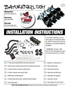
Your Master Cylinder should look something like this (3rd gen Unit Shown):
Valair Inc.
1 of 5 www.valairinc.com
2008
The three items we need to reuse are: 1. Safety Switch 2. Foam Washer 3. Rubber Washer
Valair Inc.
2 of 5 www.valairinc.com
2008
Valair Inc.
3 of 5 www.valairinc.com
2008
Once these three items have been removed we are done with the old Unit, unpack the new Hydraulic Unit, you will notice it is larger than the one you just removed, you will also notice the rod that connects the pedal to the Master Cylinder is Adjustable.
For the initial installation this rod should be screwed in as far as it will go (Shortest Length) with the Jam Nut left Loose. Now install your old Rubber Washer, Foam Washer and Safety Switch.
Key Points for Assembly and Reinstallation: •
•
Once rubber Washer, Foam Washer and Safety Switch have been installed, ensure the switch moves freely up and down the Adjustable Rod (Sliding the switch unit toward the Clutch Pedal end of the Rod, you should be able to release it and it will snap back down to the Master Cylinder end unassisted), if it does not, then it is not properly installed. Install the Master Cylinder into the Firewall bracket FIRST by feeding the rod and Safety Switch Pigtail through the hole and lining up the flat sections of the master Cylinder with the Valair Inc.
4 of 5 www.valairinc.com
2008
• •
flat sections of the bracket, then by applying a firm pushing pressure you should be able to turn the master Cylinder unit Clock-Wise 90 degrees to lock it into the bracket. The Master Cylinder should now be locked in and not feel loose or move around in the firewall bracket, if it is loose, then you need another rubber washer, or it is not fully turned in. Route the slave Cylinder down towards the Bell housing, (Note: the Line will not route the same way as the original as it is 6 inches shorter and has steel braiding). Do NOT cut the clear straps or remove the Nylon Rod End on the slave Cylinder!!!
Once the Slave Cylinder is installed into the Bell housing securely it is time to head under the dash to install the Master Cylinder Rod to the Clutch Pedal. • •
Reconnect Safety Switch Pigtail back into wiring loom Reconnect Master Cylinder Rod to Clutch Pedal
Depress Clutch pedal fully 3 – 4 times, this should break the Slave Cylinder Straps and give you full travel. With the Pedal Depressed all the way start the truck, if the truck does not start, lengthen the Adjustable rod in 1/8th increments until the safety switch will enable the truck to start, at this point lock the Jam Nut on the adjustable rod. At this point no further adjustment should be required. Test the vehicle for correct clutch engagement and disengagement and pedal height. Warning: Adjusting the Rod to its maximum length may result in Hydraulic unit damage; if the correct engagement/disengagement cannot be achieved at the shorter lengths of adjustment STOP!!! Something else is wrong!!! Valair Inc.