Project Funding • This research was funded by the US Department of Energy through the Nuclear Fabrication Consortium (operated by EWI) • The Nuclear Fabrication Consortium (NFC) was established to independently develop fabrication approaches and data that support the re-establishment of a vibrant US nuclear industry
www.autosteel.org
Project Background • Select three laser applications that offer significant productivity gains over the current processes being used in the nuclear industry
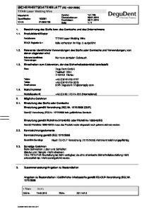
12.7-mm
– Single-pass, thick-section welding of 316L stainless steel – Single-bead per layer, narrow-groove, thicksection welding – Tube to tube-sheet welding
• Down-select an application and perform a technology demonstration for the nuclear industry Filler Metal 82 Clad
www.autosteel.org
Inconel 690 Tube
Tube-to-Tube-Sheet Heat Exchangers • Not just nuclear • Usually GTAW (TIG) welded with wire
www.autosteel.org
Demonstration Objectives • To demonstrate a compilation of commercially available equipment and technology suitable for laser welding tubeto-tubesheet on a large scale – – – –
Welding Optics Manipulator Vision System Laser
www.autosteel.org
Courtesy
Automotive Application Example: Gear Assembly Welding • Identify that all critical components have been assembled and are in the correct location. Is the Pinion Present?
Are the Teeth Present?
Is the Tab in Place?
Is the Pin Present?
Is the Pin Welded in Place?
www.autosteel.org
The Tube Sheet Welding Challenge… • Consistently finding the ‘invisible’ weld joint – Current GTAW methods can use locators that physically contact the ID of the tube – An alternative option is to visually find the center of the tube and determine the location of the joint based on the drilled hole diameter
www.autosteel.org
Mock Joint for Demonstration
Preferred Welding Optics • Several options were investigated – Standard welding optics • Dependent on a manipulator to produce a circular pattern – Remote (scanner) welding optics • Potentially the highest productivity solution, but introduces challenges for shielding gas and vision – Rotary Wedge Scanner • Preferred due to its relative simplicity, integrated shielding nozzle, and coaxial camera
– Uses the refractive optical effects of a wedge to produce precision circles (or other shapes with advanced model)
Circles result as the wedge assembly rotates
Focusing Optic
Motor and Wedge Assembly
– The diameter of the circular pattern can be adjusted by manually indexing the wedges – Coaxial camera mount for vision system integration
Camera Mount
Process Fiber Input
90º, partiallyreflective mirror
Collimating Optic
Shielding Nozzle
www.autosteel.org
Focusing Optic
Preferred Manipulator • Several options were investigated – 3-axis, CNC controlled positioner – A custom system that would mount directly to the tubesheet – 6-axis robotic
• A Fanuc robot with iRVision was selected as the preferred solution – Pre-integrated vision system eliminates the need for a third party vision package – Support from one supplier for both vision and robot support – Easily scalable to tackle large tubesheet applications
www.autosteel.org
Finding the Center of the Tube-I.D. • Welding solution assumes constant wall thickness • Lighting is essential for robust vision analysis
Trepan Center
Measured
Robot Move
www.autosteel.org
Fanuc i RVision System • The vision system (digital camera) compares what it ‘sees’ to a master image (taught during set-up) • If the current image does not match the master, a 2D offset is calculated and the robot adjusts its position Prior to the relative position offset
After the relative position offset
www.autosteel.org
Fanuc i RVision System at EWI • 1.5-kW laser power – 360-μm spot size – 80-IPM weld speed
• 49 tube welds in 5:20 (~6.5 seconds per tube) – Typical GTAW process takes nearly 2 minutes per tube – Robot speed, weld speed, and vision system program could be adjusted to further reduce cycle time
www.autosteel.org
Results • Cross-sections taken from the 2nd and 48th weld – Profile and penetration nearly identical
Inconel 600 Tube
Filler Metal 52 Clad
Inconel 600 Tube
www.autosteel.org
Filler Metal 52 Clad
Results • Additional sections showing challenges to overcome – Mis-alignment due to chamfer on ID of tube – Keyhole porosity • Contaminants at joint interface? • Keyhole instability?
Filler Metal 52 Clad
Inconel 600 Tube
Filler Metal 52 Clad
Inconel 690 Tbe
www.autosteel.org
Inconel 600 Tube
Demonstration at B&W • The equipment was set up in a temporary enclosure at B&W’s research center • A 4-kW fiber laser was supplied be IPG Photonics
• Over 150 laser welds were produced throughout the day for a group of nearly 100 people from the nuclear industry
www.autosteel.org
Summary and things to remember
• Laser tube-tube-sheet welding requires vision for precision. • Custom optics can provide local motion precision. • Laser + robot + optics + vision can offer cost effective solutions to precision joining challenges. • Vision systems (hardware and software) will become much more prevalent in robotic laser welding.
www.autosteel.org
Special Thanks • The project was completed with the support of several companies: