INDUSTRIAL AUTOMATION SEQUENCE
LOGIC
X1
X3 X4 .....................
X5
Output Signals
CIRCUIT
Fixed Automation Relays Electronic Gates Microprocessors Pneumatic Valves Moving-Part Logic (MPL)
X2
Xn
Data Processing
Semi-Flexible Automation Programmable Counters Drum Programmers Fixed Automation Programmable Controllers (PLC) Microprocomputers
TYPICAL OUTPUT DEVICES Pneumatic or Hydraulic Cylinders Pneumatic or Hydraulic Motors Solenoid Valves Electric Motors - Pumps - Conveyor Belts - Lifting Devices - Robot Arms Heaters Timers Lamps Audioble Signals (Bells, Buzzers, Sirens) Numerical Displays
Y1 Y2 Y3 .....................
Sensor Inputs
CONTROL
Y4
Ym
0546-484-231 04-8712774 ! "
3 5
1 2
Ladder Diagram PLC - Programmable Controllers
10
3
Relays MPL
5,6 "
!
5 6
#
Emergency
!
% Hardware Programmers % Drum Programmers Programmable Counters, Step
$
STOP
Counters !
'
(
( ' Trigger Flip-Flops Timers Binary Counters Shift Register '' Schmitt Triggers Encoders Binary Codes Iterative Systems
( *
% #
, ,
$
)
1
+ ,
7
&
%
'
%
+
$#
, #
%
Motion Actuators Sensors # #
GRAFCET
$
$ % Industrial Automation, by D. Pessen, John Wiley & Sons, 1989 ' ( ( # $ # ' $ # ) ' $ # ) ' + &! ! + # # %
! %
$ $
#
#
$
%
)
!& ! ! ! !* '
!
)$ #$
#
!
% $
! #
#
"
$
!
)
#
! $
#
#
% $ .
# %$ # "
#
! !(
# #
!#
$
#
# ,
(
!#
"
!
-
$ !
! " #
!#
$
#
( !
# !
# $
#
n, n-2 , n-2 ) $
$ & /
'# ! ! 25%$
# # # (
#
$
# $
(
$ $
%
$ $
$ $
! /
# $ $ !
000000000000 #
1
!
!
#
$
) 00000000000000000 #
!1
!
#
(15%)
& / $ $
$ #
# #
Meeng.technion.ac.il
studies
here
*
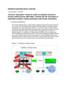
INTRODUCTION
Analog/Digital Differences Switches and Relays Pneumatic Switching Valves Cylinder Control and Sensing Other Switching Elements
0-1
INDUSTRIAL AUTOMATION
START
Automation of Mechanical Industrial Production Systems Control Section On-Off (Binary) Elements and Information Various Methodes to Obtain Low-Cost Systems
S? S?
SW SPDT SW DPDT
a. Electrical Switches K? K?
Fig. 0-1 Subject Definition
RELAY SPST RELAY DPDT
Value
b. Electro-Mechanical Relays
Value
2-Input AND Gate
3-Input NAND Gate
2-Input OR Gate Time
2-Input NAND Gate
2-Input NOR Gate
INVERTER
Time
a. Analog c. Electronic Gates Value
Value
+
-
+
Time
-
+
+
-
+
Time
b. Digital Value
d. Pneumatic Valves
Value
a1,a2 = 00
A+ Time
a2
-
+
a1
A-
(open)
(open)
Time
c. Binary (Logic, "Digital")
Fig. 0-2 Information Types
e. Electrical Limit Switches
Value
LOGIC IMPLEMENTATION
"High"
-
+
Signal
A+
A-
"Unspecified"
"Low" Time
a. Logic Levels
f. Pneumatic Limit Valves
Logic
In
Element
BINARY SENSORS : Out
Relay SPDT b. Self Correction
Fig. 0-3 Logic-Levels
Flow Switches
Interruptabel-Jet Sensors
Temperature Switches
Ultrasonic Sensors
Level Switches (Height)
Reed Switches
Photoelectric Sensors
Threshold Sensors
Pressure Switches
Magnetic Proximity Sensors
Back-Pressure Sensors
Inductive Proximity Sensors
Annular Back-Pressure Sensors
Inductive Proximity Sensors
g. Various Elements
Fig. 0-4 Binary (Switching) Elements
CHAPTER 1 BOOLEAN ALGEBRA Binary Basic Basic Boolean Operations Truth Table De-Morgan Functions Algebric Minimization Karnaugh Map Minimization
1-1
BOOLEAN ALGEBRA Logic Theory Implementation in Switching George Boole False and True replaced by 0 and 1 Binary Items and Variables Logic , Boolean , Binary , Digital Switch or Relay ON/OFF Position : Contacts : Open / Closed Net : Connected / Not-connected Binary sensors (Temperature, Pressure, etc) Representations : "0 / "1" "ON" / "OFF" "HIGH" / "LOW"
a. Basic Definitions AND
OR
NOT
0+0 = 0 0+1 = 1 1+0 = 1 1+1 = 1 {*}
0.0 = 0 0.1 = 0 1.0 = 0 1.1 = 1
0' = 1 1' = 0
b. Basic Operators
NAND (NOT AND) :
X nand Y = (X.Y)'
NOR (NOT OR) :
X nor Y = (X+Y)'
XOR (Exlussive OR)
X xor Y = X'Y+XY'
INHIBITION
X.Y'
IMPLICATION
X+Y'
f. More Useful Operators (A.B)' = A'+B' (A+B)' = A'.B' Implementations : (A.B+A'.C)' = (A'+B').(A+C') (AB(C'+DE'))' = A'+B'+C(D'+E)
g. DeMorgan Theorem AND , OR , NOT AND , NOT
A+B = (A'.B')'
OR , NOT
A.B = (A'+B')'
NAND
A' = (A.A)' = (A NAND A) A+B = (A'.B')' = ((A.A)'.(B.B)')' = = (A NAND A) NAND (B NAND B)
X+0 = X X+1 = 1 X+X = X X+X' = 1
X.0 = 0 X.1 = X X.X = X X.X' = 0
A' = (A+A)' = (A NOR A)
NOR
A.B = (A'+B')' = ((A+A)'+(B+B)')' = = (A NOR A) NOR (B NOR B)
X+X.Y = X X+X'.Y = X+Y X(Y+Z) = XY+XZ (X+Y).(X+Z) = X+YZ XY+X'Z+YZ = XY+X'Z
h. Universal Systems
c. Basic Relations
XY+X'Z+YZ = XY+X'Z F2 = XY+X'Z
F1 = XY+X'Z+YZ X
Y Z
F1
F2
0 0 0 0 1 1 1 1
0 0 1 1 0 0 1 1
0 1 0 1 0 0 1 1
0 1 0 1 0 0 1 1
0 1 0 1 0 1 0 1
d. Minimization - Truth Table
A
B C
D
F
0 0 0 0 0 0 0 0
0 0 0 0 1 1 1 1
0 0 1 1 0 0 1 1
0 1 0 1 0 1 0 1
0 0 1 1 1 1 0 1
1 1 1 1 1 1 1 1
0 0 0 0 1 1 1 1
0 0 1 1 0 0 1 1
0 1 0 1 0 1 0 1
0 0 1 1 0 0 1 1
1. Universal Sum-of-Products : 2. Universal Products of Sum : 3. Minimal Sum-of-Products : 4. Minimal Products of Sum :
1. Universal Sum-of-Products : f(A,B,C,D) = A'B'CD'+A'B'CD+A'BC'D'+A'BC'D+A'BCD+ + AB'CD'+AB'CD+ABCD'+ABCD 2. Universal Products of Sum :
XY+X'Z+YZ = XY+X'Z F1 = XY+X'Z+YZ
F2 = XY+X'Z
If Z=0 then : F1 = XY+X'.0+Y.0 = XY
F2 = XY+X'.0 = XY
If Z=1 then : F1 = XY+X'1+Y.1 = = XY+X'+Y = X'+Y
F2 = XY+X'.1 = = X'+XY = X'+Y
f'(A,B,C,D) = A'B'C'D' + A'B'C'D + A'BCD' + AB'C'D' + + AB'C'D + ABC'D' + ABC'D f(A,B,C,D) = (A+B+C+D)(A+B+C+D')(A+B'+C'+D)(A'+B+C+D). .(A'+B+C+D')(A'+B'+C+D)(A'+B'+C+D') 3. Minimal Sum-of-Products : f(A,B,C,D) = A'BC'+AC+B'C+CD 4. Minimal Products of Sum : f(A,B,C,D) = (A'+C)(B+C)(A+B'+C'+D)
e. Minimization - Math Operations
i. Functions Basic Representations
Fig. 1-1 : Boolean Algebra Concepts
1-2 Karnaugh Maps
INSURANCE COMPANY REQUIREMENTS AN INSURANCE COMPANY SELECTS CLIENTS ACCORDING TO THE FOLLOWING CRITERIA : NATIONALITY, GENDER, AGE AND HAVING DRIVING-LICENSE. CLIENT MUST SATISFY AT LEAST ONE OF THE FOLLOWING CONDITIONS : and/or ISRAELI and/or NON-ISRAELI UNDER 50 WITH DRIVING LICENSE NON-ISRAELI MAIL 50 OR ABOVE and/or
NON-ISRAELI UNDER 50 WITHOUT DRIVING LICENSE
FIND THE MINIMAL REQUIRED CONDITIONS
a. System Definition
CRETERIA
VARIABLE
NATIONALITY GENDER AGE
A B C D
LICENSE
1
0
ISRAELI MALE 50 OR ABOVE HAS LICENSE
* Visual method for boolean functions minimization * Each variable occupies half map * n variables split map into 2^n basic cells, named map Elements * Each element is represented by a n-variable boolean product, named "Minterm" * Any two adjacent elements are represented by two "Adjacent" minterms * Merging two adjacent elements produces a 2-elements cell, represented by a product of (n-1) variables
NON-ISRAELI FEMAIL UNDER 50 DOESN'T HAVE LICENSE
b. Boolean Variables Assignment
* Two adjacent 2-element cells may be merged Into a 4-elements cell, represented by a product of n-2 variables, and so on
T = A+A'C'D+A'BC+A'C'D' = A+A'(C'D+BC+C'D') = A+C'D+BC+C'D'= A+C'(D'+D)+BC= A+C'+CB= A+B+C'
a. Map Concepts and Basic Properties
c. Direct Minimzation
B
T = A+A'B'C'D'+A'B'C'D+A'BC'D'+A'BC'D+A'BCD'+A'BCD = A+A'(B'C'D'+B'C'D+BC'D'+BC'D+BCD'+BCD)' = = A+B'C'D'+B'C'D+BC'D'+BC'D+BCD'+BCD' = = A+B'C'(D'+D)+BC'(D'+D)+BC(D'+D)' = A+B'C'+B.C'+BC = A + B'C' + B(C'+C) = = A + B'C' + B = A + C' + B
e. Truth Table Minimzation SIMPLIFIED RESULT : and/or ISRAELI and/or UNDER 50 MALE
A
B
C
D
T
0
0
0
0
0
0
0
1
1 1 0 0 1 1 1 1 1 1 1 1 1 1 1 1
0
0
1
0
0
0
1
1
0
1
0
0
0
1
0
1
0
1
1
0
0
1
1
1
1
0
0
0
1
0
0
1
1
0
1
0
1
0
1
1
1
1
0
0
1
1
0
1
1
1
1
0
1
1
1
1
A
B A
B
A
0
B
1
0 1
d. Truth Table
f. Minimal Requirements
B'
A'
A
b. 2-Variables Map Representations
Fig. 1-2 : Algebric Minimization (1) AN OCTAL NUMBER IS DEFINED BY THE BINARY COMBINATION X2,X1,X0
BC 11
10
A'B'C' A'B'C
00
A'BC
A'BC'
AB'C'
ABC
ABC'
A
WHERE N(X2,X1,X0)=4.X2+2.X1+1.X0
0
A COMBINATIONAL SYSTEM DETECETS IF THE NUMBER IS DIVIDABLE BY EITHER 2 OR 3
1
a. System Definition X2
X1
X0
T
0
0
0
1
0
0
1
0
0
1
0
1
0
1
1
1
1
0
0
1
1
0
1
0
1
1
0
1
1
1
1
X1 X1 X1
AB'C
B
A
C c. 3-Variables Map Representations CD
COMBINATIONAL CIRCUIT
T
b. Block Diagram
00
AB
01
11
C
10
00 01
T = X2'X1'X0'+X2'X1.X0'+X2'X1.X0 + + X2.X1'X0'+X2.X1.X0'= =X0'(X2'X1'+X2'X1+X2X1'+X2X1)+X2'X1X0= =X0'(X2'(X1'+X1)+X2(X1'+X1))+X2'X1X0= =X0'(X2'+X2)+X2'X1X0= =X0'+X2'X1X0= =X0'+X2'X1
0
c. Truth-Table
01
d. Minimization Steps
Fig. 1-3 : Algebric Minimization (2)
B 11
A 10
D d. 4-Variables Map Representations
Fig. 1-4 : Karnaugh Maps Concept
1-3
GROUPS SELECTION - ESSENTIAL AND NON-ESSENTIAL CANDIDATES An international company has to hire employees that will be available, as a group, to support the following 6 languages : Hebrew , English , Russian , Arabic , Rumanian , French Of course, the company target is to hire the minimal number of employees, and get the required support. 5 candidates look for that job. Next table specifies the language knowledge of each candidate : Candidate A Hebrew English Russian Arabic
Candidate B Hebrew English Romanian
Candidate C
Candidate D
Candidate E
Russian Arabic
Hebrew French
Arabic Russian
There are many available combibations, but we can make the selection easier : 1. Check if there are ESSENTIAL candidates, that is to say candidate that support at least a single language, that none of the others does. These candidates are called ESSENTIAL, since are non-replacable by any of the other candidates. 2. Since all ESSENTAIL candidates (if there are any) must be a part of any selection option, we first identify them and select them. 3. NON_ESSENTIAL candidates doesn't mean that they will not be selected. NON_ESSNTIAL. Since any of them may be replcaed by others, no one can decide - on first glance - which of them must be selected,or not. 4. Actually, some (or all) NON_ESSENTIAL will have to be selected in case that the ESSENTIAL candidates do support all required languages. 5. We can see easily that French is suppoter by candidate D only, and Romanian is supported by candidate B only. This maked D and B ESSNTIAL. Each of all other languages is supported by al least 2 candidates, so all those candidates are NON_ESSENTIAL.TIAL. 6. Selection of candidates B and D (ESSENTIAL) cover more than the 2mentioned languages; they also support Hebrew and English, so we don't have to worry about support of thse 4 langages. 7. Selecting all ESSENTIAL candidates, don't cover the left languages Arabic and Russian. So, we must look for the minimal additional candidates that will completed the.This selection is simpler. 8. In this case, either A or C complete the required support, so the minimal selected group contains 3 candidate (2 ESSENTAIL and 1 ON_ESSENTIAT). 9. There is no other option to the support Arabic and Russian by a single candidate, so there two minimal available selections : a. { A , B , D} b. { B , C , D} 10. Principally, both selections are minimal. On the other hand candidate A has higher priority than C since he support 4 labguages and may be ore helpful, and a backup to the other languages that had been covered by the ESSENTIAL candidates. 11. Thsi means that first minimal selction (a) is preferable, which leaves a single minimal solution.
Fig 11-5 : ESSENTIAL and NON_ESSENTIAL concept
A
A
A
A
A
A
1
D
A
A
C
1
I
D
I
1 1 1
1 1
D
1 1
B
A
C
II
D
C
1
II
1 1
D
II
1 1 1
1 1
1
D
1 1
1 1
1 1 1
1 1
B
1 1
1 1 1
1 1
C
I
1 1
1 1
1 1 1
1 1
D
B
C
II
1 1
D
C
I
1
1 1
1 1 1
1
B A
C
F = AD + C'D + A'CD'
B
B
B
A
A
A
C
III
D
C
1
III
1 1
D
III
1 1 1
1 1
1
1 1 1 1
1 1 1
1 1
1 1
D
C
III
1 1
D
1 1 1
1
1 1 1 1 1
C
II
B
1 1 1 1 1
2
D
1 1
1 1
B
B
B
B
Essential cells : 3 Non-Essential cells : 0 Minimal solutions : 1
1 1 1 1 1
A
1 1
1
B
B
1 1
Fig. 1-6 : Example 1
1
C
I
1 1
C
1
D
1 1
1 1
1 1
C
C
D
1 1
1 D
IV
1 1 1 1 1
1
1 1
B
I
A
A D
C
1
IV
1 1
D
IV
1 1 1
1 1
1
1 1 1
1 1
1 1
C
B
B
D
1 II
A
D
V
1 1
B A
B
F1 = ABC + BC'D + A'BD' F2 = BCD' + ABD + A'BC'
Essential cells : 0 Non-Essential cells : 6 Minimal solutions : 2
Fig. 1-11 : Example 6
1
1 1 1
1 1
1 1
C
F1 = BC + B'C'D + A'BD F2 = BC + B'C'D + A'C'D
Essential cells : 2 Non-Essential cells : 2 Minimal solutions : 2
F = AC + B'C + A'BC' + CD
Essential cells : 3 Non-Essential cells : 2 Minimal solutions : 1
A
C
1 1 1 1 1 1
1
Fig. 1-8: Example 3
B
Fig. 1-9 : Example 4
A
A
C
1 1 1
1
1
D
VI
1 1
1 1 1
1 1
1 1
C
B
I II III IV V
F1 = A'C' + AC + ABD + AB'D' F2 = A'C' + AC + ABD + B'C'D' F3 = A'C' + AC + BC'D + AB'D' F4 = A'C' + AC + BC'D + B'C'D'
Essential cells : 2 Non-Essential cells : 4 Minimal solutions : 4
Function "Area" All (Maximal) Cells Minimal Solution 1 Minimal Solution 2 Minimal Solution 4
Maps Definitions
Fig. 1-10 : Example 5
F = A'C'D + ACD + A'BC + ABC'
Essential cells : 4 Non-Essential cells : 1 Minimal solutions : 1
Fig. 1-7 : Example 2
1-4
A
A
A
A
A
A
0
D
D
0
I
C
C
I
1 1
D
D
C
C
C
I
-
1
1
I
-
1
1
I
-
D
1
I
1 1 - 1 1 1
1
1 1 1 -
D
1 1 1 1 -
1 -
- 1
1
1
1 1 -
1 1 - 1
1
1 1 1 1
1 1 1 1 1 1 1
C
B
B
B
B
B
B
A
A
A
A
A
A
0 D
D
D
II
1
1
-
D
1
C
C
II
-
1
1
II
1 1 - 1 1 1
D
1 1 1 -
1
D
1 1 1 1 -
C
II
-
1
1 1 -
1 -
- 1
1
1
0
II C
C
II
1 1
1 1 -
1
1 1 1 1
1 1 1 1 1 1 1
C
B
B
B
B
B
B A
-
A
A
A
A
A
1
D
0
D
B
D
C
1
III
-
A
D
1 1 III
1 1
-
C
C
III
D
1 III
1 1 - 1 1 1
1 1
1
- 1 - 1 1 1 1
- 1
1
1
1 1 -
C
III
C
III
B
1 1 - 1
0
D
1 1
1 1 1 1
1 1 1 1 1 1 1
C
B
B
B
B
1 IV
B A
C
1 D
B
A
C
-
D
1 IV
1 - 1 1 1
1 -
F = AD + A'D'
B
Essential cells : 2 Non-Essential cells : 1 Selected Don't Cares : Partial Minimal solutions : 1
Fig. 1-17 : Example 10
F = AC' + C'D + A'CD'
Essential cells : 0 Non-Essential cells : 3 (+5) Selected Don't Cares : None Minimal solutions : 1
Fig. 1-16: Example 9
F = AD' + A'B' + BCD
Essential cells : 2 Non-Essential cells : 1 (+2) Selected Don't Cares : All Minimal solutions : 1
Fig. 1-14 : Example 8
D
C
0 B
D
VI
1 1
A
Fig. 1-18 : Example 11
I
0 0 0 -
-
1
1 1 1 1
1 1 1 1 1 1 1
C
B
C
D
II
0 0 0 0 -
0 0
B A
D
-
C
0
III
0 0 -
0 0 0
F1 = A'C' + B'D'+ AB + CD F2 = BD+ AC + A'B'+ C'D' F3 = AD'+ BC'+ CD + A'B' F4 = A'D + B'C + AB+ C'D' F5 = F6 =
Essential cells : 0 Non-Essential cells : 12 Minimal solutions : 6
Fig. 1-12 : Example 7
F1 = ACD + AB + A'C' F2 = ACD + AB + A'D' Note : F1 and F2 are equivalent but not identical
Essential cells : 1 Non-Essential cells : 5 Selected Don't Cares : Partial Minimal solutions : 2
A
A
0 0
F = (A + B' + C' + D).(A' + B + C + D')
F' = A'BCD' + AB'C'D
Essential cells : 2 Non-Essential cells : 0 Minimal solutions : 1
V
1 1
1 1 1 1
1 1 1 1 1 1 1
Fig. 1-13 : Example 7.1
D
1 1
1 1 1 1
1 1 1 1 1 1 1
C
B
Function "Area" All (Maximal) Cells Minimal Solution 1 Minimal Solution 2 Minimal Solution 4
F = (A'+B+D').(A+B'+D).(B'+C+D')
F' = AB'D + A'BD' + BC'D
Essential cells : 0 Non-Essential cells : 8 Selected Don't Cares : None Minimal solutions : 1
Fig. 1-15 : Example 8.1
I II III IV V
Maps Definitions
1-5
X
Y
Z
1-6
M
0
0
0
0
0
0
1
0
0
1
0
0
0
1
1
1
1
0
0
0
1
0
1
1
1
1
0
1
1
1
1
1
BCD to 7-SEGMENTS CONVERTER Design a combinational circuit that gets a BCD input, and converts it to 7-Segment display. BCD is short form of Binary-Coded-Decimal. It Represents 10 decimal digits (0-9) in 4-bit binary code (0000-1001). Binary combinations 1010-1111 (above decimal 9) may not appear as inputs, and are refered as don't-care.
a. System Definition
Y,Z 00
01
11
10
0
0
0
1
0
1
0
1
1
1
X
b. 7-Sigments Arrangement
M = XY+XZ+YZ
b. Karnaugh-Map
a. Truth-Table
A G B C B A E D E C F F D G
D3 D2 D1 D0
Fig. 1-19 : Majority Function
c. Block Diagram
Y,Z X
Y
Z
A
B
C
0
0
0
0
0
0
0
0
1
1
0
0
0
1
0
1
0
0
0
1
1
1
1
0
1
0
0
1
0
0
1
0
1
1
1
0
1
1
0
1
1
0
1
1
1
1
1
1
00
X 0 1
0
01
1
1
1
11
10
1
1
1
D3 D2 D1 D0
0 0 0 0 0 0 0 0 1 1 1 1 1 1 1 1
1
A=X+Y+Z Y,Z 00
X
01
11
10
0
0
0
1
0
1
0
1
1
1
B = XY + XZ + YZ
0
00
01
11
10
0
0
0
0
0
a. Truth-Table
0
1
0 1 0 1 0 1 0 1 0 1 0 1 0 1 0 1
A B C DE F G
0 0 1 1 1 1 1 0 1 1
1 1 1 1 1 0 0 1 1 1
-
-
D3,D2 00
01
11
10
00
1
1
-
1
01
1
0
-
1
11
1
1
-
-
10
1
0
-
-
D1,D0
1
0 0 1 1 0 0 1 1 0 0 1 1 0 0 1 1
d. Truth-Table (Partial)
Y,Z X
0 0 0 0 1 1 1 1 0 0 0 0 1 1 1 1
0
C = XYZ
b. Karnaugh-Maps X Y
A
Z X
E=D2'+D1'D0'+D1.D2
e. Karnaugh Map of "E"
Y X
Z
B
Y
D3,D2
D3,D2 X
Y
Z
D1,D0
C
00
c. Contact Circit Realization
01
X Y Z X
10
Y Z
Y
SWITCH X
01
11
10
D1,D0
0
1
-
1
00
0
*
1 1
*
1 0
1
-
*
1
-
01
11
10
00
01
11
0
1
-
1
0
1
-
1
Y
SWITCH Y
Z
1
0
-
-
1
-
-
A=D3+D2.D1'+D2'D1+D1.D0'=
C
SWITCH Z
=D3+D2.D1'+D2'D1+D2.D0'
f. Karnaugh Map of "A"
d. Electrical Diagram
Fig. 1-20 : Motor Operation Control (Exer 1-7)
10
1
B
X
X
A
11
00
Fig. 1-21 : BCD to 7-Segments
1-7 LAMP
SW PUSHBUTTON SW DPST
RELAY SPST SW SPST RELAY 4PST
M1 SW DPDT
SW SPDT
M2
RELAY SPDT
A
M3
B
RELAY DPST
RELAY 4PDT
M4
RELAY DPDT
C
M5
Fig. 1-22 : Various Switches and Relays Types
M6 T = AB + AC + BC = AB + (A + B)C
M7
a. Majority Boolean Function COMMON
A
L = A'B'C' M1 = A'B'C M2 = A'BC' M3 = A'BC
B C M
a. Block-Diagram
-
+
b. Switches-Operated Circuit A A B
M4 = AB'C' M5 = AB'C M6 = ABC' M7 = ABC
L=A'B'C' M1=A'B'C M2=A'BC' M3=A'BC M4=AB'C' M5=AB'C M6=ABC' M7=ABC
B C A
c. Contacts Circuit
B
C
b. Switches-Operated Circuit A
-
B'
+
B
A' B
M
C B'
A
d. Switches Remote Operation 9 Long Lines, Carrying High Current
B
C'
L=A'B'C'
C
M1=A'B'C
C'
M2=A'BC'
C
M3=A'BC
C'
M4=AB'C'
C
M5=AB'C
C'
M6=ABC'
C
M7=ABC
Long lines, high power dissipation -
c. Contacts Circuit
+
A A
B
M
B
C
B
C
C
A -
+
A B
e. Relays Remote Operation 3 Long Lines, Carrying Low Current
COMMON C
d. Relays-Operated Circuit
Fig. 1-23 : "MAJORITY" Function Circuit Fig 1-24 : 3-TO-8 DECODER CIRCUIT
L=A'B'C' M1=A'B'C M2=A'BC' M3=A'BC M4=AB'C' M5=AB'C M6=ABC' M7=ABC
Y1 Y2 Y1 Y2
1-8
X2 X1'
Y1
X2'
CR1
X1'
CR1=Y1.X2+Y2.X2'+Y1.X1'+Y2.X1 8 Contacts , 16 Springs
CR1
2 Contacts 4 Springs
X1'
X1
1 Contact 3 Springs
Y1
Y1
X1
CR1
Y2
X2
CR1
X1
X1'
X1
c. Saving Contact Springs
b. Saving Contacts
X2
X1
X1'
X2'
CR1=Y1(X1'+X2)+Y2(X1+X2') 6 Contacts , 12 Springs
a. Original Function
X1'
X1
X1
Y2
X1
X1'
X2
Y2
X2'
CR1=Y1(X1'+X2)+Y2(X1+X2') 6 Contacts , 12 Springs
CR1=Y1(X1'+X2)+Y2(X1+X2') 4 Contacts , 10 Springs
d. Changing circuit schema
e. Saving Contact Springs
Fig. 1-25 : Saving Contacts and Contacts Springs Y2 Y3
Y2 T
Y1
Y3 T
Y1 Y1
Y2
Y3
Y2
T=Y2.Y3+Y1.Y3+Y1.Y2.Y3'
a. Original Function
Y3
T=Y2.Y3+Y1.Y3+Y1.Y2.Y3'+(Y2.Y3') = Y2 + Y1.Y3
b. Sneak Path Y2.Y3'
Fig.1-26 : Sneak Path Creation Exitation Function (Y)
Output Variables (y,y')
Y
RELAY
Output Function (T)
Input Variables (x')
y y y
x1 x2 x3 x4
y' y' y'
a. Use of Relay
T GATE
b. Use of Gates
Fig. 1-27 : Devices Outputs (fan-out) NOT
AND
OR
EXCLUSIVE OR
NOR
NAND
IMHIBITION
Old European Symbols
FLIP-FLOP S
Y
R
Y'
Old USA Symbols
S
New Symbols Recommended by ISO
Q FF
R
1
&
>1
=1
>1
&
Fig. 1-28 : Logic Gate Symbols
&
Q'
S
Y
R
Y'
1-9
C
- - - 0 - 1 - 0 0 0 0
A
1
A'
A
B+A'D
A'D D
D
D
C'(B+A'D)
B
B
B
C'
C
C
b. Gates Implementation of (a) - 5 Gates
T=BC'+A'C'D= =C'(B+A'D)
a. Prime Cells Selection C
A
D
- - - 0 - 1 - 0 0 0 0
1
C
C B
B
A
C'
B A
D
(B+A')C'D B+A'
A'
d. Gates Implementation of (c) - 4 Gates
D T=BC'D+A'C'D= =(B+A')C'D
c. Non-Prime Cells Selection
Fig. 1-29 : Minimize by Selecting Non-Prime Cells Input Variables
Xn
.....
Multiple Output System
.....
X1 X2 X3
Output Variables
Input Variables
T1 T2 T3
A B C D
Tm
a. General Case
Output Variables Multiple Output System
T1 T2
b. Specific Case
Fig. 3-30 : Multiple Output System
C
0
0
0
-
1 A
1
0 1 1
1 1
0
C
0
1
0 0 0
D T1=AC'+BCD (Instead of A'C+BD)
a. Function T1
0 B A
1
1
0
1
1
A
0
1
0
0
0
0
0
D
AC'
C'
0
0
A
B
C D B
T1=AC'+BCD
C D B B
BCD
T2=A'B+BCD A'B
A'
T2=A'B+BCD
b. Function T2
C. Gates Implementation
Fig. 1-31 : Minimize by Selecting Non-Prime Cells, in Multiple-Ourtut System
CHAPTER 2 RELAYS CASCADE SYSTEMS Ladder Diagram Relays, Cylinders, Valves Symbols Sequential Sequences Relays Cascade Implementation Huffman Method Flow Diagram Primitive and Merged Flow Tables State Assignment Output and Excitation Functions
2-1 "YES"
Switching Circuit-1
Load-1
Switching Circuit-2
Load-2
Switching Circuit-3
Load-3
"YES"
Switching Circuit-4
Load-4
"XOR"
| | |
| | |
Switching Circuit1-n
Load-n
"YES"
"YES"
"AND"
"OR"
a. General Schematics 220V
Fig. 2-1 : Ladder Diagram START
b. Example - Home Electric Ladder Network
STOP CR1
CR1 a2
a1
STOP
A-
-
+
A+ START
a2
a1
-
+
a. Basic Circuit
A+
CR1
CR1
a. Valve Without Return Spring
b. Basic Contacts Circuit
b. Valve With Return Spring
Fig. 2-4 : Cylinder Actuation Valves Set Circuit
Reset Circuit
CR1
CR1
c. General Circuit a1,a2 = 00
a1,a2 = 10
Fig. 2-2 : Set-Reset Relay Flip-Flop
a1
a2
A+
START
(Closed)
A-
(open)
-
A+
A-
CR1
(open)
b. Position "Moving"
a. Position "-"
STOP
CR1 CR1
Red Lamp
a1,a2 = 01
Green Lamp
A+
a2
-
+
a1 CR1
A-
(open)
(Closed)
a. Example - Schematic Circuit
c. Position "+" START
STOP
Voltage 8
6
2
RELAY CR1 5
Red Lamp
Fig. 2-5 : Positions of Cylinder Limit Switches
1
7
3
4
Green Lamp
b. Example - Wiring Diagram
Fig. 2-3 : Flip-Flop Implementation Example
a2
-
+
+
a1
a. Normally Open
b. Normally Closed
Fig. 2-6 : Graphic Symbols of Limit Switches
(open)
2-2
A Sequence of Drilling Two Holes in a Wodden Plate B
+
+
+
A
C
Cylinders States Cylinder "A" fastens/reases the wooden plate. Cylinder "B" lowers and lifts a driller..
5. Cylinder "B" lowers the driller thus performing drilling action 6. Cylinder "B" lists the driller thus disconnecting it from the plate 5. Cylinder "C" returns the driller to its initial position, and cylinder "A" releases the wooden plate.
2
3
4
5
6
7
8
START
a. Process Mechanical Representation
Process starts by pressing START pushbotton 1. Cylinder "A" fastens the wooden plate 2. Cylinder "B" lowers the driller thus performing drilling action 3. Cylinder "B" lists the driller thus disconnecting it from the plate 4. Cylinder "C" shifts the driller to next hole location.
1
+ A + B + C -
-
A. Cylinders Position Chart
1
+ A + B + C -
Cylinders States
2
3
4
5
6
7
8
a1 a2 b1 b2 c1 c2
Limit Switches
START
b. Sequence Description
B. Cylinders Position Chart & Contacts START , A+ , B+ , B- , C+ , B+ , B- , AC-
c. Sequence Short Representation
Cylinders States
+ A + B + C -
1
2
3
4
5
6
7
8
Cylinders States
Limit Switches
START
d. Cylinders Sequence Process Chart
Fig. 2-7 : Process Sequence Representations
VALVE
+ A + B + C -
1
2
3
4
5
6
7
a1 a2 b1 b2 c1 c2
+ A + B + C -
C. Cylinders Position Chart, Contacts & Valves Position
Fig. 2-8 : Sequence Chart Diagram
Fig. 2-2 : "Intuitive" Design Problems
8
2-3 START,A+,A-,B+,10 Sec delay,B(STEPS :
1
2
3
4
5)
a. Process Sequence (No Return Springs) START
b1
A+
b. Step 1 : Actuate A+
START
b1
cr1
a2
b2
A+
CR1
cr1
START
b1
A+
a2
A-
A-
cr1
cr1 PROBLEM Long Start causes Actuation of A+ and A- simultaneously
B+
a1
b2
c. Step 2 : Actuate A-
TMR B-
tmr Add reset (b2') to CR1
START
b1
cr1
A+
f. Correct problems of (e)
A-
a2 cr1
CR1 B+
a1
START
b1
cr1 CR2
PROBLEM B+ is also actuated before cycle starts
A+
cr2 a2
b2
d. Step 3 : Correct and Actuate B+
CR1
cr1 A-
cr1 cr1
START
b1
A+ cr1
a2
a1
CR3
CR1 cr3
cr1 cr1
A-
cr1
B+
b2 a1
TMR tmr
b2
B+
B-
TMR tmr
B-
g. Isolate Limit Swithes from Solenoids Current
PROBLEM B+ and B- are actuated simultaneously. CR1 is actuated infinitily
e. Steps 4-5 : Correct and Actuate TMR and B-
Fig. 2-9 : "Intuitive" Design Problems
2-4
RELAYS CASCADE SYSTEMS * Avoid conflicting actuation of a cylinder
START , A+ , A- , B+ , C+ ,
* Distinguish between situations where a cylinder performs more than a single cycle
I
II
CA+ III
, A- , BIV
Fig. 2-12 : Typical Groups Partitioning * Maximal size groups (to obtain minimum number of group relays) * Same "Letter" may appear no more than once in a group (to avoid conflicted commands to a cylinder) * Except for specific cases, groups Partitioning doesn't depend on having or not having valves return springs
START
cr3'
cr4'
cr2' CR1
cr1 cr1
Fig. 2-10 : Cascade Method Target & Rules
cr3' Group 1 Termination
CR2
cr2 cr2
cr4'
Group 2 Termination
CR3
cr3
START , A+ , A- , B+ , C+ ,
CA+
, A- , B-
cr3
a. Sequence List Representation
1
2
3
4
5
6
7
Group 3 Termination
Group 4 (Last) Termination
CR4
cr4
8
9
Group(s)
cr
A+ Condition(s)
A+ A-
Group(s)
cr
ACondition(s)
B+ BC+
Group(s)
cr
B+ Condition(s)
CSTART Group(s)
a2
cr
BCondition(s)
a1 b2
Group(s)
b1
cr
C+ Condition(s)
c2 c1
Group(s)
b. Sequence Chart Representation
Fig. 2-11 : Typical Process Definition
cr
CCondition(s)
Fig. 2-13 : Typical Initial Cascade Circuit, of 3-Cylinder / 4-Groups Process
B+
A-
, C+ , A+
C, A- , B-
cr3
cr2 cr4 cr2 cr3
B+ BC+ C-
cr
cr
cr
III
A+
C-
a1
a1 b2
b1
cr4'
cr3'
Fig. 2-14 : Relay Cascade Design Process 1 (No Return Springs)
C-
C+
B-
B+
A-
A+
CR4
CR3
CR2
CR1
IV
, A- , B-
cr2'
d Complete Circuit
cr4
cr2
cr3
cr1
cr4
a2
c2
cr2
a2
cr1
c1
cr
c. Total Initial Circuit
II
, C+ ,
cr3' cr4'
A-
cr3
cr2
cr1
START
cr
CR4
CR3
CR2
CR1
A+
cr4
cr4'
cr3'
cr2'
B+
A-
b. Groups Partitions
I
START , A+ ,
cr
cr3
cr3
cr2
cr1
cr3' cr4'
cr2
cr1
START
a. Process Sequence Information
2. Valves are actuated electrically (solenoids).
return springs.
1. Cylinders are actuated by 5/2 valves without
START , A+ , B+
A, C+ , A+
C, A- , B-
cr4
cr4'
cr3'
cr2'
C+
B+
A+
CR4
CR3
CR2
CR1
c1
cr4
cr3
cr2
cr3
cr1
cr4
II
, C+ ,
a1
a1
a2
b2
b1
cr4'
cr3'
cr2'
d. Complete Circuit
cr2
cr3
cr3
c2
cr2
a2
cr1
cr3' cr4'
cr2
cr1
START
B+
A-
III
A+
C-
b. Groups Partitions
I
START , A+ ,
B+ duration
C+
B+
A+
CR4
CR3
CR2
CR1
IV
, A- , B-
Fig. 2-15 : Relay Cascade Design Process 1 (With Return Springs)
c. Total Initial Circuit
cr
cr
cr
cr3
cr3
cr2
cr1
cr3' cr4'
cr2
cr1
START
a. Process Sequence Information
2. Valves are actuated electrically (solenoids).
return springs.
1. Cylinders are actuated by 5/2 valves with
START , A+ ,
2-5
cr4'
cr3'
cr2'
III
D-
D+
C-
C+
B-
B+
A-
A+
CR4
CR3
CR2
CR1
b. Groups Partition
II
c2
a2
a1
b2
d1
a2
c1
cr4
b1
cr3
d2
cr2
a1
cr4'
cr3'
cr2'
d. Complete Circuit
cr3
cr2
cr2
cr1
cr3
cr1
cr4
cr2
cr3
cr1
cr3
cr2
cr1 cr1
cr1
START cr3' cr4'
(IV)
Fig. 2-16 : Relay Cascade Design Process 2 (Without Return Springs)
c. Total Initial Circuit
cr
cr
cr
cr
cr
cr
cr
cr
cr4
cr3
cr2
cr1
cr3' cr4'
cr3
cr2
cr1
START
I
START , A+ , B+ , C+ , C- , A- , D+ , A+ ,D- , B- , A- ,
a. Process Sequence Information
1. Cylinders are actuated by 5/2 valves without return springs. 2. Valves are actuated electrically (solenoids).
START , A+ , B+ , C+ , C- , A- , D+ , A+ , D- , B- , A- ,
D-
D+
C-
C+
B-
B+
A-
A+
CR4
CR3
CR2
CR1
cr3
cr2
cr3'
cr2'
I
D+
C+
II
III A+
a2
a1
b2
d1
a2
c1
cr3
d2
cr2
c2
a1
(IV)
b1
cr3'
cr2'
Fig. 2-17 : Relay Cascade Design Process 2 (With Return Springs)
d. Complete Circuit
cr3
cr2
cr2
cr3
cr2
cr1
cr3
cr3
cr1
cr2
cr1
cr1
START cr3'
Notes : CR4 been canceled (useless). Rset CR3 been corrected Contact a1 been added to Set CR1
D+
C+
B+
A+
CR3
CR2
CR1
b. Groups Partition
c. Total Initial Circuit
cr
cr
cr
cr
cr2
cr1
cr1
START cr3'
cr2'
B+ START , A+ , B+ , C+ , C- , A- , D+ , A+ , D- , B- , A- ,
A+
a. Process Sequence Information
1. Cylinders are actuated by 5/2 valves with return springs. 2. Valves are actuated electrically (solenoids).
START , A+ , B+ , C+ , C- , A- , D+ , A+ , D- , B- , A- ,
D+
C+
B+
A+
CR3
CR2
CR1
2-6
2-7
"ON-DELAY" TIMER DEFINITION As long as input is "0", output is also "0". When input changes from "0" to "1", output change to "1" is delayed by T sec. When input changes from "1" to "0", output changes to "0" immediately, and time count resets to 0. Note : Element behaves as a slow activated relay : it changes to active state only T sec after been energized, but returns to rest state as soon as energizing terminates.
IN
"ON-DELAY" TIMER
OUT
IN
OUT
5 Sec
4 Sec
5 Sec
TIME Timing chart of a 5-Sec delay timer (example)
Fig. 2-17 : "On-Delay" Timer Definition
CHAPTER 3 PLC (Programmable Logic Controller) PLC Definition PLC Hardware Control System PLC Programming Programming LIFO Stack Implementation Timers and Counters Modified Programming Commands Standard I/O
PLC - Programmable Logic Controller
3-1
Micro-computer for controlling industrial processes First applied at 60th-70th Implement binary and analog signals, PID Eliminate need to implement relays and its wiring Cost economical, requires small space Contains timer' counters and more Perfect reliability Solution to the design of complex systems Easy to program and easy to change it Input/output are adapted to high voltage/current devices Reliable operation under industrial conditions Built in self diagnostics May be controlled and monitored by central computer Not economic for small control processes Slow but OK for industrial timimg
a. General
Programming Unit
Central Processing Unit (CPU) Memory
Input Modules Output Modules
Controlled System
PLC
b. Block Diagram of PLC
3-1. Programmable Controller (PLC) Representation
Limit Switches Proximity Switches Photoelectric Switches Sensor Switches (Level, Pressure, Temperature etc) Push-Button Switches Selector Switches Relay Contacts
a. Discrete Input Devices to PLC
Contact Relay Coils Valve Solenoids Pneumatic or Hydraulic Cylinders and Motors Lights Audible Alarms (Bells,Buzzers,Sirens) Fans Heaters Motor Starters
b. Discrete Output Devices Actuated by PLC 12, 24, 48, 120, 230 Volt AC 12, 24, 48, 120, 230 Volt DC 5V DC (TTL Level) Conract Relay Output
c. Standard Discrete I/O Interface Modules
3-2. PLC Interfaces
Field signal may not be connected directly to PLC Converts field signals to logic level, and vica versa Adapted to implement DC and AC signals Contains protection from voltage transients and noise Contains protection from oposite polarity connectios Electrical common isolation Expensive Adapted to work in industrial conditions
3-3 Input/Output Modules
m
004
003
n
PLC Program Coding
002
001
000
007
006
005
004
003
002
CR
b. Remote-Mounted I/O
PLC
..........
Fig. 3-5 : Different I/O Connection Location
a. PLC-Mounted I/O
PLC
I/O Modules (PLC Mounted)
..........
I/O Modules (Field Mounted with Multiplexer)
..........
Controlled System
Fig. 3-4 : General I/O Connection Diagram
Controlled System
Level FS5
Level FS4
Temp TS3
STOP
START
Limit Switch 2
001
000
.........
Limit Switch 1
Output Modules
................
Switch
Input Modules
Relay
Solenoid
Bulb
Solenoid
Motor
PROCESS 2
PROCESS 3
PLC 2
PLC 3 HOST
STAR
a. PLC Typical Network
PROCESSOR
PLC 7
RING
PROCESS n
PLC n
b. Several Possible LAN Topologies
PROCESS 1
PLC 1
PLC 4
PLC 6
PLC 6
Fig. 3-6: PLC Macro Networks
BUS
PROCESS 4
PROCESS 6
PROCESS 5
PLC 9
PLC 8
PROCESS 9
PROCESS 8
PROCESS 7
3-2
INPUT DEVICES
3-3
INPUT MODULES
OUTPUT MODULES
CPU SENSOR 1
HIGH/LOW VALUES
INPUT MODULE 1
LOGIC LEVEL
X1
SENSOR 2
HIGH/LOW VALUES
INPUT MODULE 2
LOGIC LEVEL
X2
PLC
OUTPUT DEVICES
Y1
LOGIC LEVEL
OUTPUT MODULE 1
HIGH/LOW VALUES
LOAD 1
Y2
LOGIC LEVEL
OUTPUT MODULE 2
HIGH/LOW VALUES
LOAD 2
Ym
LOGIC LEVEL
OUTPUT MODULE M
HIGH/LOW VALUES
LOAD m
CR1
HIGH/LOW VALUES
SENSOR n
CRk
LOGIC LEVEL
INPUT MODULE N
Xn (LOGIC LEVEL)
Fig. 3-7 : PLC General Configuration
PLC SYSTEM
INPUT MODULE 1
a1
X0
CPU a2
INPUT MODULE 2
a1
INPUT MODULE 3
X1 X2
Y1
Y2
OUTPUT MODULE 1
OUTPUT MODULE 2
A+
a2
-
Start
+
START
CYLINDER SYSTEM
+
-
A-
Fig. 3-8 : Typical PLC Control System Example
C-
D+ START , A+ ,
C+
Input Modules
, C- , A- ,
B+ , A+ , C+ , B- , D- ,
AStart
a. Process sequence
X0 X1 X2 X3 X4 X5 X6 X7 X8
START
a1 a2 b1
b2 c1 c2 d1 d2
b. Input Table
Y1
A+
Y2
AB+ BC+ CD+ D-
Y3
Y4 Y5 Y6 Y7 Y8
Y1 Y2 Y3 Y4
c. Output Table no return springs
Output Modules
A+ B+ C+ D+
X0
a1
X1
Y1
A+
a2
X2
Y2
A-
b1
X3
Y3
B+
b2
X4
Y4
B-
c1
X5
Y5
C+
c2
X6
Y6
C-
d1
X7
Y7
D+
d2
X8
Y8
D-
d. Output Table with return springs
PLC (no return springs) e. PLC and I/O System
Fig. 3-9 PLC I-O Variables Assignment
3-4 Typical air-condition system is operated by two push-botton switched : START button that operates the system STOP button that deactivate the system System is turned-on by pressing STARTbutton, and remains activated after releasing the button System is tuened-off by pressing STOP button, and remains de-activated after releasing the button A red LED is illuminated as long as the system in on
Air Condition Control Panel
On LED Off
In addition, control circuit is also equipped with a temperature sensor, that protects the system from over-heat (by turns it off)
Start
ACS
System
Stop T.S.
LED
b. Block Diagram a. Air-Condition System (ACS) representation
(Temperature Switch) START
T.S.
STOP
CR1
CR1
ACS
CR1
Start Stop T.S.
X17
X17 X18 X19
ACS LED
Input Module
X18
X19
Y13 Y15
PLC Y13
Y15 Input Module
X18
(No isolation problem since all I/O are isolated by modules)
f. Simplified Ladder Diagram
d. I/O Assignment Table
X17
Y15
Y13
Y13 Y15
Input Module
Y13
CR1
e. PLC "Internal" Ladder Diagram
OUTPUT INPUT MODULE MODULE
T.S.
CR1
CR1
LED
c. Relay Ladder Diagram for ACS
Stop
X19
CR1
(ACS supply must be isolated from sensors)
Start
X18
X17
CR1
Output Module Output Module
X19
d. PLC Ladder Diagram Fig. 3-10 PLC Control for Air-Condition System (ACS)
ACS LED
STORE
X17
OR AND
NOT
Y13 X18
AND
NOT
X19
OUT
Y13
OUT
Y15
g. PLC Program
cr6
cr2
cr1
cr3
b2
d2 C+
B+
Y12 Y13
Output Module
b. I/O Assignment
Input Module X3 X4 X5
cr8
x3
x3
x3
cr3
cr3
X4
X5
cr3 X5
Y13
Y12
CR8
Y13
Y12
e. Simplified Ladder Diagram
cr6
x4
cr2
cr1
c. PLC Ladder Diagram
cr6
cr2
cr1
cr2
cr1
Fig. 3-11 : Simplification of PLC Ladder Diagram
Connected to a2 b2 d2 B+ C+
a. Partial Ladder Diagram of a Control System
a2
0 1 2 3 4 5 6 7 8 9 10
12
0 1 2 3 4 5 6 7 8 9 10 11 Y13
x3 cr1 cr2 cr3 x5 Y12 x3 cr1 cr2 cr3 x4 cr6
x3 cr1 cr2 cr3 CR8 X5 Y12 cr8 X4 cr6 Y13
f. PLC Program (simplified)
STORE AND OR AND NOT OUT AND OUT STORE AND OR OUT
d. PLC Program
OUT
STORE AND OR AND NOT AND OUT STORE AND OR AND NOT AND OR
3-5
3-6
Command STORE first stores current value in a stack, while "pushing down" previous stack elements, and then clears latest calculated value. Action is similar to loading weapon stack. Commands that refer to stack - such as "AND STORE" , "OR STORE" etc - perform operation on current "upper" stack element (the one that been last entered), and deletes that element from stack, while "Pushing up" previous eelements. Action is similar to unloading a weapon stack, or shooting.
WEAPON STACK
Empty
1st
2nd 1st
3rd 2nd 1st
2nd 1st
1st
4th 1st
1st
WEAPON STACK
WEAPON STACK
WEAPON STACK
WEAPON STACK
WEAPON STACK
WEAPON STACK
WEAPON STACK
Load
Load
Load
Shoot
(1st in)
(2nd in)
(3rd in)
(3rd out)
Shoot
Load
(2nd out)
(4th in)
Shoot (4th out)
WEAPON STACK
Shoot (1st out)
3-12 PLC LIFO Stack concepts X2
cr10
X4
cr11
Y5
STORE NOT AND STORE NOT AND OR OUT
CR5
CR10
CR11
X2
CR6
CR2
CR3
CR1
a. Ladder Diagram
a. Ladder Diagram
0 1 2 3 4 5
X1
STORE NOT AND STORE NOT AND NOT OR STORE NOT AND NOT STORE AND NOT OR AND OUT
X2 CR10 X4 CR11 STORE Y5
b. PLC Programming of (a)
Fig. 3-13 : Use of LIFO Memory Stack
X1 CR5 X2 CR6 STORE CR10 CR11 CR2 CR3 STORE STORE CR1
b. PLC Programming of (a)
Fig. 3-14 : Multiple Use of LIFO Stack X2
cr10
X4
cr11
X1
x3
Y4
a. Ladder Diagram
0 1 2 3 4 5 6 7 8
STORE NOT AND STORE NOT AND OR STORE NOT AND OR OUT
0 1 2 3 4 5 6 7 8
X2 CR10 X4 CR11 STORE X1 X3 STORE Y4
b. PLC Programming Option 1
STORE NOT AND STORE NOT AND STORE NOT AND OR OR OUT
X2 CR10 X4 CR11 X1 X3 STORE STORE Y4
c. PLC Programming Option 2
3-15 : LIFO Use Oprions
cr3
b. Relays Cascade Circuit
cr4
cr2
cr3
C-
C+
cr1
b2
B-
cr4
a2
B+
cr1
CR4
CR3
A-
c1
b1
cr4'
CR2
CR1
cr2
a1
c2
c1
cr3'
cr2'
A+
cr4
cr3
cr4'
c2
cr2
cr1
cr3'
cr1
cr2
cr1
START
I
B+
A+ C+
AII
CIII
C+ IV
C-
B-
x5
c1
Y3
B+
Y6
C-
cr3
X6
X2
cr4
cr3
X5
cr2
X6
X1
x4
X5'
X3'
y4'
cr3'
y2'
d. PLC Cascade Circuit
cr4
cr2
cr3
cr1
cr4
cr1
cr2
cr1
cr2
cr1
cr1
cr3' cr4'
Fig. 3-16 : PLC Cascade System Design
c. PLC Variables Assignment
Y5
C+
Y4
Y2
A-
B-
Y1
A+
x6
x4
b2
c2
x3
b1
x2
x1
a1 a2
x0
START
a. Process sequence Groups partitining
START
X0
Y6
Y5
Y4
Y3
Y2
Y1
CR4
CR3
CR2
CR1
cr2 Y2 STORE OUT
cr2 x1 cr4 Y6
cr4 Y4 cr1 x2 x4 cr3 Y5
e. PLC Program
STORE AND OR OUT
STORE OUT STORE AND AND OR OUT
cr1 Y3
cr1 Y1
STORE OUT
STORE OUT
x6 cr4 x3 x5 STORE CR4
x5 cr3 cr4 CR3 AND OR STORE NOT OR NOT AND OUT
CR2 AND OR AND NOT OUT
x0 cr3 cr4 cr1 cr2 CR1 x6 cr2 cr3 AND OR AND NOT OUT
STORE AND NOT AND NOT OR AND NOT OUT
3-7
cr3
b. Relays Cascade Circuit
cr4
cr2
cr3
C-
C+
cr1 b2
B-
cr4
a2
B+
cr1
CR4
CR3
A-
c1
b1
cr4'
CR2
CR1
cr2
a1
c2
c1
cr3'
cr2'
A+
cr4
cr3
cr4'
c2
cr2
cr1
cr3'
cr1
cr2
cr1
START
x3 x4 x5
b1 b2 c1
Y6
C+
AII
CIII
C+ IV
C-
B-
d. Optimize CR Relays
Y4 = CR4
Y2 = CR2
Y1 = CR1
y4
y2
cr3
y1
y1
X5
X2
X6
cr3
y4
X1
y4'
X6 y2
y1
cr3'
x4
X5'
X3'
y4'
cr3'
y2'
e. PLC Cascade Circuit
cr3
y2
y1
X0
Fig. 3-17 : PLC Simplified Cascade of Fig. 3-16
c. PLC Variables Assignment
C-
Y5
C+
Y3
B+ Y4
Y2
A-
B-
Y1
A+
x6
x2
x1
a1 a2
x0
START
c2
I
B+
A+
a. Process sequence Groups partitining
START
Y6
Y5
Y3
Y4
CR3
Y2
Y1
Y1 Y3 X2 X4 CR3 Y5 Y2 X1 Y4 Y6
STORE OUT AND AND OR OUT STORE AND OR OUT
f. PLC Program
X6 Y4 X3 X5 STORE Y4
X5 CR3 Y4 CR3
Y2 Y1 X6 Y2 CR3 Y2
X0 CR3 Y4 Y1
AND OR STORE NOT OR NOT AND OUT
AND OR AND NOT OUT
AND OR AND NOT OUT
STORE AND NOT AND NOT OR AND NOT OUT
3-8
3-9 1. Read & store status of all external inputs (Xi) 2. Run program commands in its written order 3. Wait until end of scan time (*) 4. Return to (1) and start new cycle
a. PLC Scan Cycle Order
1. Input variables (Xi) status cannot be changed by program commands, and remains unchanged until next cycle 2. Output variables (Yi) and internal variables (CRi) status are controlled by PLC program. They are updated once during each cycle 3. Program commands refer to latest update of the variables.
b. Variables Status During Scan Cycle
I/O Update
Variables States
at Beginning of Scan
y7 cr4 x4 x4 y7 cr6
This Scan
Next Scan
CR2
Y7=0 , CR2=0
Y7=1 , CR2=1
CR6
CR4=0 , CR6=0
CR4=1 , CR6=1
Y7
X4=1 , Y7=1
CR4
X4=1 , CR4=1
CR5
Y7=1 , CR5=1
Y8
CR6=0 , Y8=0
CR6=1 , Y8=1
c. Effect of Scanning Action on Relay States
Fig. 3-18 : Effect of Scanning Action in PLC
X1
cr1 Y1
X1 CR1
STORE AND NOT OUT STORE OUT
X1 CR1 Y1 X1 CR1
X1 Y1
a. Proper Rung Order
X1 CR1 X1
cr1 Y1
STORE OUT AND NOT OUT
X1 CR1 CR1 Y1
X1 Y1
b. Improper Rung Order
Fig. 3-19: Importance of Proper Rung Order (Pulse Shaper)
Scan Period
3-10 RIGHT
cr1
WRONG
cr1
Y1
cr2
Y1
cr2
STORE OR OUT
cr1 cr2 Y1
SCHEMATIC DRAWING
Y1
STORE OUT STORE OUT
cr1 Y1 cr2 Y1
PLC PROGRAM
CR1=1 CR2=0
CR1=1 CR2=0
STORE OR OUT
cr1 cr2 Y1
1 1+0=1 Y=1
STORE OUT STORE OUT
SPECIFIC CASE
cr1 Y1 cr2 Y1
1 Y=1 0 Y=0
PROGRAM FLOW
END-LOOP RESULT
Y=0
Y=1
a. NEVER SPLIT OUTPUT FUNCTION INTO 2 (OR MORE) OUTPUT SUB-FUNCTIONS
WRONG
RIGHT START
STOP
START
CR1
CR1 CR1
STOP
CR1
CR1
MOTOR
MOTOR
MOTOR
MOTOR
Motor current flows through separate contact, thus isolated from input sensors
Motor current flows through sensors)
b. LOAD MUST BE ISOLATED FROM SENSORS
Fig. 3-20 : Right/Wrong Cases
3-11
X1
X2 X3
cr1
X1
CR1
X2
X4 cr1
X2 STORE STORE STORE AND OR AND OUT STORE AND
X4
X3
CR1
X1 X2 X3 X4 STORE
X2
STORE AND OR AND OUT STORE AND
STORE
CR1 cr1 X2
X3 X4 X2 X1 CR1 cr1 X2
b. Programmable Simplified Circuit
a. Original Circuit
X3
X4
X1
CR1
X2 cr1
X2
c. Ladder Sub-Circuit STORE AND OR AND OUT STORE AND
X3 X4 X2 X1 CR1 cr1 X2
d. PLC Program
STORE AND OR AND OUT AND
X3 X4 X2 X1 CR1 X2
e. Simplified Program
Fig. 3-21 : PLC Program Simplification
3-12
TIMERS AND COUNTERS The following implement PLC timers and counters of two companies : General Electrinc (GE) Texas Instruments (TI) Note : Examples refer to specific PLCs. Actually there exist a lot of different timers and counters.
Fig. 3-22 : PLC Timer And Counter Models
delay
delay
delay
TMR1 (in) Time
tmr1 (out)
a. "On-Delay" Definition
X1
TMR1
COUNT
OUT
F1
(120) tmr1
TMR1
COUNT
OUT
(120)
tmr1
X1=1 Timer Enabled and counting time X1=0 Timer is Reset
b. Specific Case
c. General Case
Fig. 3-23 : PLC "On-Delay" Timer Model (GE)
3-13
Flash Control
Switch
Flash Light
a. Flash Block Diagram
Flash light is actuated while switch is on Switch Flash
b. Flash Timing Diagram
x1
tmr2 tmr1 tmr1
TMR1 TMR2
Y1
(0.5 Sec) (0.5 Sec) (Light Valve)
c. PLC Ladder Diagram
x1 TMR1 tmr1=Y1 TMR2 tmr2
d. Detailed Timing Diagram
Fig. 3-24 : Design Flash-Light system using "On-Delay" timers
3-14
X1 TMR1 (200)
X2
X1=1 Timer Run X2=1 Timer Enabled
empty
F1
CR1
F2
X1=0 Timer Stops X2=0 Timer is Reset
STORE STORE TMR1 200
X1 X2
OUT
CR1
a. Specific Case
TMR (n)
CR1
F1=1 Timer Run F2=1 Timer Enabled
F1=0 Timer Stops F2=0 Timer is Reset
b. General Case
5
2
1
2
Count Reset Out 5
10
20
15
25
30
c. Timing Diagram (Delay=0.5 Sec)
Fig. 3-25 : 2-Input PLC Timer (TI - Texas Instruments)
X1
CR2
X1
CR2
TMR1 (5)
Y1
empty
y1 TMR2 (5)
y1
CR2
empty
a. Ladder Diagram
X1
(5)
empty Y1
y1 y1
TMR (5)
X1 CR2 X1 CR2
y1 y1 y1
CR2
b. Programming of (a)
CR2 TMR
STORE AND NOT STORE AND NOT TMR1 5 OUT STORE STORE TMR2 5 OUT
CR2
c. Simplified Ladder Diagram
empty
STORE NOT STORE TMR1 5 OUT STORE STORE TMR2 5 OUT
CR2 X1
Y1 y1 y1
CR2
d. Programming of (c)
Fig. 3-26 : Design Flash-Light system using TI timers
35
3-15 A security lock is to be opened only on confirmation of two managers, simultaneously. Each manager confirms by turning on a personal switch (A and B). In order to make sure that a single manager will not be able to turn on both switches, the switches been located far from each other, and lock is to be opened only if the two switches are turned on within 0.5 Sec. If one switch is turned on at least 0.5 Sec before second switch is turned on, the security lock is disabled, and may later be open after releasing the pressed switch and repeat the process. After being opened, the lock is closed as soon as any of the switches is turned off. a. Security Lock Specifications
Switch A Switch B
X1 X2
Lock
Y1
b. PLC I/O table TMR (5)
x1
CR1
(0.3 Sec)
x2
Y1
Y=1 when both switches are operated Missing timing dependence
x2
CR1
x2
Y1
Y=1 when both switches are operated, and timer output tmr1 is off Missing timer actuation
c. Solution Step 1
d. Solution Step 2
x1
x1
TMR
x2
(5)
x1
CR1
(0.3 Sec)
x2
x2
TMR
x2
(5)
x1
CR1
(0.3 Sec)
x2
x2
CR1
Y1
x1
x2
CR1
Y1 y1
Timer is actuated by either of the two switches. If timeout occurs before seconad swithced been turned, lock is diabled
If Y1 been set to "1", it keeps be connected by by-passing cr1 contact (acts as flip-flop).
Timer output always is set to "1" after 0.5 Sec. This disables lock even if it had been opened correctly.
e. Solution Step 3
f. Solution Step 3 - Complete Solution
Fig. 3-27 : Two-Hands Circuit Using PLC
3-16
X1
F1
CTR (25)
X2
CTR (n)
CR1 F2
X1= O-->1 One count X2=1 Counter Enabled
X2=0 Counter is Reset
CR1
F1= O-->1 One count F2=1 Counter Enabled
a. Specific Case
F2=0 Counter is Reset
b. General Case
empty
STORE STORE CTR1 25
X1 X2
OUT
CR1
c. Programming of (a)
Fig. 3-28 : PLC Two-Input UP Counter (TI)
X1 (Up/Down) X2
(Event)
X3
(Reset)
CTR3
F1 CTRi
F2
(120)
F3
(Up/Down) (Event)
CTRi (n)
(Reset)
CTRi
Y2
X1 determines UP or DOWN mode X2= O-->1 One count X3=1 Counter Enabled X3=0 Counter is Reset
Y2
F1 determines UP or DOWN mode F2= O-->1 One count F3=1 Counter Enabled F3=0 Counter is Reset
a. Specific Case
b. General Case LOAD NOT LOAD NOT LOAD NOT OUT 120 LOAD OUT
X1 X2 X3 CTR3 CTR3 Y1
c. Programming of (a)
Fig. 3-29 : 3-Input UP/DOWN Counter (GE)
3-17 START,(D+,D-) repeat 6 times,D+,10 Sec DELAY,Da. Required Sequence D
Input Modules
d2
D-
Output Modules
Connected to
Y1 Y2
START d1 d2 D+ D-
X0 X1 X2
-
+
d1
D+
b. Cylinder Type
c. PLC I/O Table
x1 (d1)
Y1
Infinite cycles
x2 (d2)
Y2
d. Solution Step 1
x1 (d1)
cr1
x2 (d2)
cr1
Y1
Y2
x1 (d1) x0 (Start)
COUNTER 1 (6)
CR1
e. Solution Step 2
x1 (d1)
cr1
x2 (d2)
cr1
Y1
Y2
cr2 x1 (d1) x0 (Start)
x2 (d2) cr1
COUNTER 1 (6)
TIMER 1
(100)
Circuit performs 6+1/2 Cycles, and stops
CR1
CR2
(10 Sec)
f. Solution Step 3 - Complete Circuit
STORE AND NOT OUT
x1 cr1 Y1
STORE NOT OR AND OUT
cr1 cr2 x2 Y2
STORE STORE NOT CTR1 6 (NOT USED) OUT STORE NOT STORE TMR1 100 (NOT USED) OUT
x1 x0
CR1 x2 cr6
CR2
g. PLC Programm
Fig. 3-30 : Step-By-Step Design of Sequence START,(D+,D-) repeat 6 times,D+,10 Sec DELAY,D-
3-18 An elevator exists in a 5-floor building. Elevator runs automatically (without human control), from 1st floor to 5th floor, and vica versa, while stopping for 10 seconds in each floor. Each floor is equipped WITH a unique contact, that is closed when the elevator reaches that floor. These contacts are implemented as input sensroes for PLC control system. a. System Description
1st
2nd
3rd
4th
5th
INPUT MODULE INPUT MODULE INPUT MODULE INPUT MODULE INPUT MODULE
X1
X2
X3
PLC Y1
OUTPUT MODULE
Y2
OUTPUT MODULE
UP
MOTOR
MOTOR
DOWN X4
X5
b. PLC System Configuration
X1 X2 X3
CR0
X4 X5 CR0
COUNT
TMR1
CR0
X1
OUT
(100)
CR1
RESET
X5
CR2
CR2 CR1 CR0 CR1 CR0
CR2
CR2
Y1
Y2
Notes : CR2 control elevator direction Y1 - Up direction Y2 - Down direction
STORE OR OR OR OR OUT AND TMR1 100 (NOT USED) OUT STORE OR AND NOT OUT STORE OR NOT AND OUT STORE OR NOT AND NOT OUT d. PLC Program
c. PLC Ladder Diagram
Fig. 3-31 : "Saturday" Elevator
X1 X2 X3 X4 X5 CR0 CR0
CR1 X1 CR2 X5 CR2 CR1 CR0 CR2 Y1 CR1 CR0 CR2 Y2
3-19
Property
Relays System
a. Signal Flow
PLC System
Parallel
Serial
b. Number of Contacts
Limitted
Unlimitted
c. Adding Relay
Expenssive
NO cost
d. Timers / Counters
Expenssive
e. Reliability
Limmted
f. Support
Required
X1
g. Races
NO cost
Almost unlimmited
Almost not required
X1
cr1
cr1 Y1
Y1 X1
X1
CR1
CR1
Possible
h. Non Serial Parallel
X1
CR1
X5 X2
(CR1 = X1.X3+X2.X4+ +X1.X5.X4+X2.X5.X3)
i. Sneak Path
X3
Impossible
X4
Possible
X1 X3
X2
CR1
CR2
CR1 = X1.X2 + X3.X4.X2 CR2 = X3.X5 + X1.X4.X5
Possible
X3
X2
X4
X1
X5
X4
X2
X5
X3
CR1
Impossible
X4 X5
X1
X1
X2
X3
X4
X3
X5
CR1 = X1.X2 + X3.X4.X2 CR2 = X3.X5
Impossible
Fig. 3-32 :Differences Between Relay and PLC Ladder Diagram
CR1
CR2
STORE MCR
b. Programming Lines
X6 3
b. Programming Lines
X6 3
Fig. 3-35: Jump (JMP) Command
c. Command Definition
If X6=0, then the next (3) outputs are frozen, and the PLC continues its scan at the rung following the third output
a. Ladder Diagram
JMP(3)
STORE JMP ...
X6
...
Fig. 3-34 : Master Control Relay (MCR) Command
c. Command Definition
If X6=0, then the next (3) outputs are kept at logic "0" (shut off)
a. Ladder Diagram
MCR(3) ...
X6
...
Fig. 3-33 : Support Other Data Types
Byte/Word format (binary groups) Digital to/from Binary Mathematical Operations Matrix Operations Digital/Analog conversion More
Register Y
+ = Register Z
ADD Register X
Overflow Output
Register Y
Register X
COMPARE
> =
2
D
C
Xn "1" An+1 "0" Bn+1
P=1
1
"0" Cn+1 "0" Dn+1
d. General Cell Flow Chart
Xi
X0
An
Ai-1
Ai
A1
A0
Bn
Bi-1
Bi
B1
B0
Cn
Ci-1
Ci
C1
C0
Dn
Di-1
Di
D1
D0
d. Iteratice Block Diagram Pi-1
Xi
Pi
0
0
0
Ai-1
0
1
1
1
1
0
1
1
1
1
0
e. General Cell Truth Table
Pi = Pi-1.Xi' + Pi-1'.Xi = Pi-1 xor X f. General Cell Function Xi
-
Bi-1 Ci-1
Di-1 Xi
Ai
Bi
Ci
Di
0
1
0
0
0
1
0
1
0
0
0
0
1
0
0
1
0
0
1
0
0
0
0
1
0
1 0
0 0
0 0
0 0
1 1
1
0
0
0
1
- - - - 1 - 1 - - 1 - 1 - - 1 - - 1
e. General Cell Truth Table 4
Pi-1
5
6
1
c. General Cell Flow Chart
0
0
1
N=0
A
c. Iterative Block Diagram
P=0
0
0
Pi
g. General Cell Logic Circuit
Fig. 9-4: Iterative Parity Checker
Ai = Ai-1.Xi' Bi = Ai-1.Xi + Bi-1.Xi' Ci =Bi-1.Xi + Ci-1.Xi' Di =Ci-1.Xi +Di-1 f. General Cell Function
Fig. 9-5 : Iterative 2-Out-of-n Checker
*
9-3 DESIGN OF A BINARY COMPARATOR Comparator compares 2 binary numbers X,Y (of equal length), and produces 3 output signals: Line A : A=1 if X>Y Line B : B=1 if X=Y Line C : C=1 if XY) (X=Y) (X