Proceedings of the World Congress on Engineering and Computer Science 2013 Vol II WCECS 2013, 23-25 October, 2013, San Francisco, USA
Improved Design of a Flour Milling Machine Nwogu, Uchenna Celestine and Ikebudu, Kingsley O . ABSTRACT - The research presents improved design of a flour milling machine. It is a machine used for the milling of flour (dough) to a higher degree for food production without damaging the nutrients. In the construction of the design it is expected to use indigenous technology and to increase efficiency, minimize cost and maximize profit. The machine was designed to use the main drive shaft as means of speed reduction. It is very cheap to maintain.
I.
INTRODUCTION
Milling machine is used for cutting the gear; the gear blank is mounted on the arbor which is supported between a dead centre and a live centre at the indexing head. The cutter is mounted on the arbor of the milling machine. The geometric centre of the cutter must be aligned exactly vertically with the centre line of the indexing head spindle. The table of the machine is moved upward until the cutter touches the periphery of gear blank. The vertical feed dial is set to zero. The table is then moved horizontally until the cutter clears the gear blank. The table is then moved upward equal to the full depth of the gear tooth. The vertical movement may be less if the gear is to be cut in two or more passes. After this, the longitudinal feed of the table is engaged. The gear blank moves under the rotating cutter and a tooth space is cut. At this stage, the movement of the table is reversed so that the cutter again clears the gear blank. The gear blank is then indexed to the next position for cutting the second tooth space. This procedure is repeated until all the teeth have been milled. The table frame, the motor mounting frame, the main frame mounting plate and the drive shaft are all made of mild steel because of its good properties of hardness and tough resistance. The inner surface of the table is made of galvanized mild steel which is hard, tough and corrosion resistant to avoid contamination of food during the production process of the food in the flour milling machine. To overcome the problem of the ancient use of concave stone, quern mill, norse mill of the 65BC and wind mill of the 11th and 12th centuries, a roller mill machine was on the increase and available to power the industries. Later, the demand for high speed white flour roller mills and refining system were developed toward the end of the 19th century. Basically, the flour milling machine with rollers enhances the flour (dough) when mixed in a large quantity which is used by some of the food industries for food processing i.e. bakery industries, biscuit industries and fast food making centers etc.
The authors are with DEPARTMENT OF MECHANICAL ENGINEERING, ANAMBRA STATE UNIVERSITY, NIGERIA Email:
[email protected]
ISBN: 978-988-19253-1-2 ISSN: 2078-0958 (Print); ISSN: 2078-0966 (Online)
The use of the flour milling machine by some of our food industries has increased the rate of their production and as well saved a lot of time in production process. In this research work, the machine will be modified from the old design which does not have the pinion drive gear; rather the speed reduction was done with an auxiliary gear box which is usually driven by an automotive engine of six horse powers. This modified machine uses the main drive shaft as means of speed reduction and these involves a big pulley of the main drive shaft being driven by a small pulley with the aid of electric motor. The pinion gear of the main drive shaft drives the big gear of the base which in turn drives the upper roller of the system. From these arrangements, there is an automotive speed reduction, therefore, the gear box system is unnecessary because of the inbuilt speed reduction arrangement. The machine is plugged directly to electricity (A/C) and can also be driven by an automatic system. The modification design will yield a compatible power supply, cheaper to install and maintenance cost is reduced. II.
SURVEY
Before the introduction of the mechanical flour milling machine, concave stones known as saddle stones were used by many cultures and numerous fine examples exist today. Grain placed on the stone like bowl would be pulverized by manually moving the second stone backward and forward. Experimentation with the shape of the top crushing stone eventually led to the development of a round stone used in a circular motion and the development of the quern. At about 1000BC various civilizations had developed quern mills. A quern mill consisted of a flat circular stone which crushed grain between its two flat surfaces. As querns became refined, holes were made in the top stone to introduce grain or to hold a handle that could be used to turn a stone easily. The small early hand mills were enhanced in size by some organized societies such as the Romans who used donkeys and slaves to provide the power to turn large scale stones. The Greeks harnessed streams and rivers for the first water powered mills. Observing the apparent power of running water led to the development of water mills known as norse mills. Horizontal paddles placed in moving water turned a vertical shaft which would be connected to mill stones for grinding. Early records showed that norse mills was working in Asia in 65BC and their success led to the wide spread development of water mills. Windmills were used in Europe in the 11th and 12th centuries The roller milling with the increase availability of power, the industrial revolution and demand for good white flour, the speed roller mills and refining system were developed towards
WCECS 2013
Proceedings of the World Congress on Engineering and Computer Science 2013 Vol II WCECS 2013, 23-25 October, 2013, San Francisco, USA
DESIGN ANALYSIS OF MATERIALS
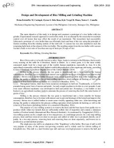
The materials required in the designs are as belows: (a) The Main Frame (b) The Rollers (c) The Gears (d) The Table (e) The Electric Motor Mounting Frame (f) The Smooth Rods (g) The Drive Shaft (h) The Pulley Drive (i) The Motor (j) The Belt (k) The Ball Bearing (l) The Key (m) Nuts And Bolts (a) The main frame is made of angle bars of 60mm thick and length of 100mm. It is cut on the work bench to sizes and chamfered to fit the desired figure shown below and coupled with four mounting bar which are made of smooth rods of length 6.20mm and thickness 30mm. It is threaded at both end and bolted to the mainframe for the rigidity of the frame. The metal that is used for the fabrication of the main frame is mild steel. It is an alloy of iron and Carbon, with carbon content up to a maximum of 0.45%.
65mm
35mm
620mm
65mm
14 0 m m
III.
(c) The rollers are made with mild steel pipe of thickness 6mm, diameter of 140mm and length of 620mm. The diameter shaft diameter is 35mm and they are produced by mounting the pipe on the vice and cutting off from 6mm thick pipe with diameter of 110mm. The roller shaft is made of mild steel rod that has spline coupling (i.e. Austin motor parts) the assembling of these three parts gives you the roller and after welding of the three parts an eccentricity of the machine is obtained. A hotten pipe is used for the roller to reduce the nominal local of the motor.
11 0 m m
the end of the 19th century. Originally designed by a Swiss named Heifenburger in 1874. This newer method of milling crushed the grains between a series of fluted metal rollers using a reduction process. The fine flour articles sifted out at each pass, returning the residue to the next set of steel roller. The development of roller mills enables greater quantities of white flour to be made at high speed. (M) Nuts and bolts
A Roller The rollers are mild steel; they are hard and tough to resist abrasion and twist. They are hollow pipes with thickness of 6mm, the hollow nature of the roller helps to reduce the nominal load of the motor and to reduce the weight of the machine, as well as to reduce the cost of procuring a solid pipe. (d) The gear systems are made with mild steel, the two gears have an outer raising of 155mm and inner raising of 140mm each while the pinion which is connected to the drive shaft has an outer raising 100mm and inner raising of 75mm. They are made with a high speed steel which have valuable property of retaining their hardness.
The Gear The gear is also made of mild steel which has the valuable property of retaining their hardness even when heated up to red heat.
Angle bar of the main frame
Bolt
Pitch Circle: It is an imaginary circle, which by rolling action would give the same motion as the actual gear. (b) The main frame mounting plate is reduced from 6mm Pitch Circle Diameter: This is the diameter of the pitch circle; thick mild steel flat sheet and the pattern cut out as the size of the gear is usually specified by the pitch shown circle diameter. Pitch Point: It is a common point of contact between two 50mm pitch circles. 270mm Pitch Surface: It is the surface of the rolling disc which the meshing gears have replaced at the pitch circle. Pressure Angle or angle of Obliquity: The angle between the common normal to two gear teeth at the point of contact and the common tangent at the pitch. Addendum: It is the radial distance of a tooth from the pitch circle to the top of the tooth. Dedendum: It is the radial distance of a tooth from the 360mm The hole for the mounting of the roller bearing are bored pitch circle to the bottom of the tooth. 50mm
320mm
90mm
180mm
Smooth rod
ISBN: 978-988-19253-1-2 ISSN: 2078-0958 (Print); ISSN: 2078-0966 (Online)
WCECS 2013
Proceedings of the World Congress on Engineering and Computer Science 2013 Vol II WCECS 2013, 23-25 October, 2013, San Francisco, USA
Key Way
Key Way
60mm
20m m
Addendum Circle: It is the circle drawn through the top of the teeth and is concentric with the pitch circle. Dedendum Circle: It is the circle drawn through the bottom of the teeth (root circle) Circular Pitch: It is the distance measure on the circumference of the corresponding point on the next tooth (PC) Circular pitch Pc = UD/T D = Diameter of the pitch circle T = Number of teeth of the wheel Diameter pitch: It is the ratio of number of teeth to the pitch circle diameter in millimeters Diameter pitch Pd = T/D = U/PC Module: It is the ratio of the pitch circle diameter in millimeters to the number of teeth Module m = D/T Clearance: It is the radial distance from the top of the tooth to the bottom of the tooth in a meshing gear. A circle passing through the top of the meshing gear is called clearance circle Total depth: It is the radial distance between the addendum and the dedendum circle of a gear. It is equal to the sum of the addendum and dedendum. Working Depth: It is the radial distance from the dedendum circle to the clearance circle. It is equal to the sum of the addendum of the two meshing gears. Tooth Thickness: it is the width of the tooth measured along the pitch circle. Tooth Space: It is the width of space between the two adjacent tooth measured and the pitch circle. Backlash: It is the difference between the tooth space and the tooth thickness as measured on the pitch circle. Face of the Tooth: It is surface of the tooth below the pitch surface. Topland: It is the surface of the tooth below the pitch surface. Flank of the Tooth: It is the surface of the tooth below the pitch surface. Face Width: It is the width of the gear tooth measured parallel to its axis. Profile: It is the curve formed by the face and flank of the tooth. Fillet Radius: It is the radius that connects the root circle to the profile of the tooth. Path of Contact: It is the path traces by the point of contact of two teeth from the beginning to the end of engagement. Length of the Path: It is the length of the common normal cut-off by the addendum circles of the wheel and pinion. Arc of Contact: It is the path traced by a point on the pitch circle from the beginning to the end of engagement of a given pair of teeth. (e) The drive shaft, the pinion gear and bearing are mounted on the drive shaft. That is a bar of thickness 60mm with length of 620mm which both of its end are machined to accommodate the gear, the bearing and the drive pulley.
130mm
620mm
Drive shaft A shaft is a rotating machine element which is used to transmit power from one place to another, the power is delivered to the shaft by some tangential force and the resultant torque set up within the shaft permits the power to be transferred to various machine linked up to the shaft. To transfer the power from one shaft to another, various members such as pulleys and gears are mounted on it. These members along with the force exerted upon them causes the shaft to bending. POWER TRANSMITTED TO THE SHAFT Torque T = Power P
=
Where N Recall that
= =
1450rev/min of the motor.
Where T = Twisting moment acting on the shaft j = Polar moment of inertia of the shafts about the axis of rotation Ō = Tension shear stress r = Distance from neutral axis to the outermost fiber. Since a solid shaft is used, the polar moment of inertia J is J
=
Therefore, the Torque transmitted by the shaft Ō = 320mpa ∏ T = /16 x Ō d3 ∏ T = /16 x 320 x 302 = 0.1963x 320 2.000 = 1696032.00 16960 x103 N/mm Therefore Power P
=
= P
= =
25739w 2.6kw
LENGTH OF THE OPEN BELT r1= 145mm, r2= 110mm, X = 1.32mm
r
r2 r1
ISBN: 978-988-19253-1-2 ISSN: 2078-0958 (Print); ISSN: 2078-0966 (Online)
WCECS 2013
Proceedings of the World Congress on Engineering and Computer Science 2013 Vol II WCECS 2013, 23-25 October, 2013, San Francisco, USA
The belt is an open belt drive; both the pulleys rotate in the same direction. r1 and r2 = Radii of the larger & smaller pulley X = Distance between the centers of the two pulleys L =Total Length of the belt Length L=(r1+ r2) + 2X + =(145 + 110) + (2x + Where X =1.32mm =
(255) + 2(1.32) +
=
800.7 + 2.64 +
= L
800.7 + 2.64 + 928 = 1731mm
Power transmitted Power (P) = (T1 – T2) V = (1696000 – 844) 17.7 = 169515 x 17.7 = 300043 = 3000W = 3.0 KW Efficiency of the drive P1 = If the rev/m (N) = 117rev/m P1
= =
P2
= 3012 =
Power transmitted by the belt Torque (T) =
=
16960 x 102 NT-mm
Speed V =
= 2998 Efficiency (X)
=
=
=
= = 17. 7m/s Let T2 = Tension in the slack side of the belt 2.3log (T1/T2) = µ.0 Where θ = 160o θ= 0.25 (Coefficient … friction But θ = 160 x∏/180 = 2.793 : . 2.3log (T1/T2) = 0.6980 log (T1/T2) =
=
700mm 650mm
660mm 610mm
log (T1/T2) = 0.3036 (T1/T2) = 2.01 T2
= 0.9954 = 99.5% (f) The table is made of angle bar 50mm x 50mm which is covered with galvanize mild steel sheet of 1mm thickness and length 650mm x 610mm
= = 84378 = 844N –mm
Torque in the shaft of the smaller pulley Ts = (T1 – T2)r2 = (16960 – 844) 110 = (1695 x 110 = 18645 N-mm Torque in the shaft of the larger pulley TL = (T1 – T2)r1 = (1696000 – 844)145 = 16952 x 145 = 24579 N –mm
ISBN: 978-988-19253-1-2 ISSN: 2078-0958 (Print); ISSN: 2078-0966 (Online)
Mild Steel Galvanized mild steel
The Table (g) The ball bearing has an outer rising of 72mm and inner rising of 35mm and it is made of steel because of the high local stress of varying magnitude with each revolution of the bearing. The balls are generally made of high carbon chromium and steel. The material of both the balls and races are heat treated to give extra hardness and toughness. The balls are manufactured by hot forging on hammers from steel rod. They are then heat treated ground and polished, the races are also formed by forging and then heat treated ground and polished. For an easy transmission of power from the motor via the belt to the driven shaft, a ball bearing is used to affect efficiency and transmission of force to the gears as illustrated above. Oil or light grease is used for lubricating the bearing. Only pure mineral oil or calcium base grease should be used. If there is a possibility of moisture content, then potassium or sodium base grease may be used. Another additional advantage of the grease is that it forms a seal to keep out dirt or any other foreign substance. The temperature should be kept below 90oC and should not operate above 150oC.
WCECS 2013
Proceedings of the World Congress on Engineering and Computer Science 2013 Vol II WCECS 2013, 23-25 October, 2013, San Francisco, USA
In order to select the most suitable ball bearing, first of all, the basic dynamic redial load of the bearing was calculated using this formula. L = (c/w)K x 166 revolutions Then, multiply by the service factor (Ks) to get the design basic dynamic radial load capacity. Where L = Rating life C = Basic Dynamic load K = 3, for ball bearing.
two parts to be joined together, causing it to be permanently joined. Some of the parts are also coupled with nuts and bolts so that they can be easily dismounted and remounted repeatedly. REASONS FOR USING WELDING OPERATION FOR THE ASSEMBLING 1. The welding provides very rigid joints. This is in line with the modern trend of providing rigid frames. 2. A welded joint has the great strength of the parent metal itself. 3. In welded connections, the tension member is not weakened as in the case of rivet joint. 4. The welded structure is smooth in appearance, therefore it looks pleasing. 5. The welded joints provide maximum efficiency (may be 98%).
LIFE OF THE BEARING The life of the bearing is the number of revolution of hours at some given contact speed which the bearing runs before the first evidence of fatigue develops the material of one of the rings or one of the rolling element. The minimum life is used to denote the rating life, it has been found that the life which 50 percent of a group bearing will complete or exceed is approximately 5 times the life which 90 PAINTING percent of the bearing will complete or exceed. The machine is painted to prevent rusting of the parts and to avoid corrosion of the frames. Also, the painting was used to THE NUT & BOLT / WELDING The nut and bolt is used to fasten some of the parts together beautify the machine. and in some most cases welding machine and electrode is used TESTING AND VALUATION to ensure the erection of the machine. Before testing, grease is applied to the gear and the bearing is not greased because of the fact that they are greased and sealed in the industry. Then the system is connected to the power IV. ASSEMBLING OF THE MACHINE source and tested. The main frame is coupled with four mounting bars, which are made of smooth rod of length 620mm and thickness 30mm. it is threaded at both end and bolted to the mainframe. V. MACHINE PERFORMANCE The pinion gear and bearing are mounted on a drive shaft (i.e. a bar of thickness 60mm and length 620mm) which both of its When the motor is started, the shaft of the motor pulley is end is machined to accommodate the gear, the bearing and the rotating and a force is transferred to the pulley of the driving drive pulley. One of the rollers with the bearing is coupled at shaft of the machine through the two (2) B-belt rotate as well, each of its end and the gear is mounted on the mainframe causing the gear of one of the rollers to rotate but in opposite direction of the rotating pinion. The second gear of the roller is above the pinion, so that it will engage with it. The table is mounted on the mainframe as well. In a form that also rotating but in the same direction with the rotating pinion it gives enough clearance to the first roller. The gear with its (i.e. that the two rollers are turning in opposite direction) bearing assembly is mounted above the first roller, the engagement of the first and the second roller and the pinion are The movement of the two rollers of the machine in these well aligned with that of the first roller. directions causes the flour (dough) to be milled in this In other to enhance smooth drive, the motor mounting frame machine. The performance of the machine is satisfactory. was welded on the base of the mainframe along with its motor; the pulley of the motor is aligned with the pulley of the pinion drive shaft. VI. MAINTENACE Two B-belt of size 1520mm are used to couple the electric By definition, maintenance is any activity designed to keep motor pulley and the pinion drive shaft pulley together, in a equipment or assets in working condition and may be planned form that the tensioning of the belt is moderate. The gear cover or unplanned. plate is then mounted on the mainframe to cover the bearing Lubrication of the ball bearing. from entangling with movable object and from dust. 1. To reduce friction and wear between the sliding parts of the bearing. EQUIPMENTS FOR THE ASSEMBLING OPERATION 2. To prevent rusting or corrosion of the bearing surface. 1. Welding machine 3. To protect the bearing surface from water or dirt. 2. Electrode 4. To dissipate the heat. 3. Nut and bolt The following should always be done to maintain the life of the 4. Spanner machine: The joint parts are welded together with the use of electric a) Grease should be applied to the gears and pinion to welding machine and electrode, which fuses at the edges of the reduce friction and wear between the rotating teeth.
ISBN: 978-988-19253-1-2 ISSN: 2078-0958 (Print); ISSN: 2078-0966 (Online)
WCECS 2013
Proceedings of the World Congress on Engineering and Computer Science 2013 Vol II WCECS 2013, 23-25 October, 2013, San Francisco, USA
b) The machine should be subjected to a routine maintenance to avoid breakdown of the machine. c) The rollers of the machine should be oiled with groundnut oil after use to prevent corrosion and should be cleaned with a little flour before using for the normal milling operation. d) The mainframe of the machine should be painted to prevent it from corroding. e) The bearing should be lubricated to reduce friction, wear and to protect its surface from water, dirt etc and also to dissipate heat. Finally, the machine should be allowed to rest at least six (6) hours, twice a week. VII.
VIII.
COST ANALYSIS
Costing is the determination of the actual cost of a component after adding different expenses incurred. This work begins with the pre-planning stage of the product and ends only after the whole lot of the product has been fully manufactured. Table 1 and 2 show the materials cost and the overhead cost (machine cost) Table 2 :OVERHEAD COST (MACHINE COST)
RECOMMENDATION
For the best and effective performance of the flour milling machine, the following instructions must be noted. I. The gears should be greased at least once a month to reduce friction and wear between the rotating teeth. II. The rollers should be oiled with groundnut oil after use to prevent corrosion and contamination of the flour. Also it should be cleaned with a little flour before using for another milling operation. III. The bearing should be lubricated to reduce friction, wear and rusting and also to protect its surface from water, dirt and to dissipate heat. IV. The machine should be allowed to rest at least six (6) hours twice a week. V. The bearing and the gears should be covered always with the cover plate (bearing/gear housing plate) to protect it from dirt and other objects.
LABOUR COST IN FLOUR Number of students worked = 1 Pay per Hour = N200 Number of days spent on the project = 16 days Total number of hours spent = 16days X 7hrs = 112hrs Then, Labour cost = 112hrs x N200 = N22, 400 TOTAL COST OF PRODUCTION Material Cost = N46, 730.00 Overhead Cost = N 14,735.00 Labour Cost = N 22,400.00 N 83,865.00
Table 1: MATERIAL COST
ISBN: 978-988-19253-1-2 ISSN: 2078-0958 (Print); ISSN: 2078-0966 (Online)
WCECS 2013
Proceedings of the World Congress on Engineering and Computer Science 2013 Vol II WCECS 2013, 23-25 October, 2013, San Francisco, USA
IX.
CONCLUSION
This project is quite an engineering construction that requires a huge amount of money to be achieved. The construction of the flour milling machine involves the application of all the principles of construction which includes: measurement, marking out, milling operation, cutting, joining, filling, bolting and painting. Also, the behavior of mechanism machine is not left out as that of the gear system used in the course of producing the machine. The electric motor is able to transmit through the belt to the pulley of the shaft via the pinion and then to the gears thereby causing the flour to be milled. Finally, it can be conveniently concluded that this improved design is quite a big task. However, it is interesting and inspirational as we were able to get the basic and fundamental information towards further research to the construction and production of the milling machine.
REFERENCE [1]. JOSEPH E. SHIGLEY, Mechanical Engineering
[2]. [3]. [4]. [5].
Design 6th Edition, McGraw Hill Company Inc New York, 2001. KHURMI, R.S., Theory Of Machines 14th Edition, S. Chand and Company Ltd Ram Naggar Indian, 2005 KHURMI, R.S. Et Al, Machine Design 13th Edition, S. Chand and Company Ltd Ram Naggar Indian, 2005 RAJPUT R.K., Strength Of A Machine 4th Edition, S. Chand and Company Ltd Ram Naggar Indian, 2006 SHARMA, P.D., Production Engineering 10th Edition, S. Chand and Company Ltd Ram Naggar Indian, 2006
ISBN: 978-988-19253-1-2 ISSN: 2078-0958 (Print); ISSN: 2078-0966 (Online)
WCECS 2013