Highly Accurate Extrinsic Calibration of Terrestrial Laser Scanner and Digital Camera for Structural Monitoring Applications Mohammad Omidalizarandi*, Jens-André Paffenholz, Ulrich Stenz, Ingo Neumann Geodetic Institute Leibniz Universität Hannover, Nienburger Str. 1, 30167, Hannover, Germany {zarandi, paffenholz, stenz, neumann}@gih.uni-hannover.de Abstract. In the current state-of-the-art, monitoring and analysis of short- and long-term deformations of natural and artificial objects (e.g. dams, bridges, towers, landslides,...) has received increasing interest by researchers and operators who are involved in this field of Geodetic science and engineering. In order to improve the accuracy of deformation monitoring and analysis, terrestrial laser scanner (TLS) and high resolution digital camera are integrated to optimally combine their information. TLS can directly provide 3D spatial coordinates of the object surface in combination with reflectivity values. In addition, digital cameras can acquire high resolution images. The information from both camera and TLS are complementary to each other. The strength of one measurement method overcomes the weakness of the other one. In order to fuse the acquired data from these two kinds of sensors in the common coordinate system, it is a vital and pre-requisite step to precisely determine the extrinsic parameters between TLS and digital camera. Thus, the calibration of the aforementioned hybrid sensor system can be separated into three single calibrations: calibration of the camera, calibration of the TLS and extrinsic calibration between TLS and digital camera. Camera calibration and TLS calibration (internal error sources) are commonly performed in advance in a 3D laboratory. In this research, we focus on the high accurate estimation of extrinsic parameters between fused sensors on the basis of target-based calibration using different types of observations (image measurements, TLS measurements and laser tracker measurements for validation) by considering different weights. Space resection bundle adjustment is solved based upon Gauss-Markov and Gauss-Helmert model. At the end, three case studies are investigated in the 3D laboratory and numerical results of the aforementioned calibration are presented and discussed. The results depict that ______________________________ * Corresponding author.
high accurate extrinsic parameters are achieved with applied Gauss-Helmert model and variance component estimation in the integrated multisensor-system. Finally, a real world case study of a selected structural monitoring project is presented and discussed. Keywords. Terrestrial Laser Scanner, Digital Camera, Multi-Sensor-System, Extrinsic Calibration, Deformation Analysis
1 Introduction Today, monitoring and analysis of short- and longterm deformations of natural and artificial objects (e.g. dams, bridges, towers, landslides,...) has received increasing interest both in Geodetic science and engineering applications. In this work, integration of TLS (here the Zoller+Fröhlich IMAGER 5006) and high resolution digital camera (here NIKON D750) affords increasing the accuracy of deformation monitoring and analysis by high accurately estimation of the extrinsic parameters between fused sensors as preliminary stage. TLS can directly provide fast and reliable 3D spatial coordinates of the object surface in combination with reflectivity values. In addition, digital cameras can acquire high resolution images with high quality colour information. In the combined sensor system, high resolution cameras are beneficial due to having high angular accuracy of sub-pixel accuracy image measurements which would improve the lateral accuracy of laser scanners (Schneider and Maas (2007)). On the other hand, combination of TLS and digital camera is worthwhile due to increasing the redundancy in the adjustment procedure. In addition, in case of large incidence angle of the TLS, digital images are more advantageous in deformation analysis of artificial objects. Furthermore, by the usage of digital
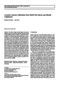
images, deformation analysis in both direction of laser beam and perpendicular to laser beam is possible. In this specific study, the digital camera is rigidly mounted on top of the TLS by the usage of a clamping system (figure 1 (left)). To avoid any vibration of camera and blurring of images, Nikon wireless mobile utility application is setup on the cell phone and images are taken indirectly. Mounting a digital camera externally on the top of the scanner has an advantage of flexibility of the used sensors. (e.g. cameras with a different resolution or focal length) (Wendt and Dold (2005)). As a drawback, in case of disconnecting clamping system for transportation, calibration should be performed for each mount. In order to overcome this problem, Omidalizarandi and Neumann (2015) applied mutual information based calibration for in situ calibration which is based upon adaption of Pandey’s work (Pandey et al. (2012)) to the integrated system of TLS and camera and results seem promising.
Fig. 1 A Nikon D750 24.3-megapixel digital camera is rigidly mounted on top of the Z+F Imager 5006 TLS (left), Leica AT901LR LT (right)
This paper addresses the topic of high accurate extrinsic calibration of terrestrial laser scanner and digital camera for structural monitoring applications. Under this approach, focal length of the camera, exterior orientation parameters between TLS and camera, exterior orientation parameters between TLS and laser tracker (LT (figure 1 (right))) and target coordinates are estimated with high accuracy. LT as an additional sensor allows extreme accuracy of the target points (Positional accuracy of 15 µm + 6 µm/m (Leica Geosystems,
PCMM system specifications (2010)) and can be considered as a reference coordinate frame. In addition, its measurements are performed independently from the integrated sensor system. In the multi-sensor-system, estimation of extrinsic calibration parameters between fused sensors is an important and preliminary procedure to obtain geometric transformation parameters between different sensors and to relate acquired data. The extrinsic calibration parameters between digital camera and TLS, six degree of freedom (6 DOF), are the position and orientation of the digital camera relative to TLS, that is identifying the rigid body transformation from the digital camera coordinate system to the TLS coordinate system. Extrinsic calibration parameters between TLS and LT, seven degree of freedom (7 DOF), are the scale, position and orientation of the TLS with respect to LT that is so called similarity transformation. The rigid body transformation allows re-projection of the 3D point clouds from the TLS coordinate system to the 2D camera coordinate system. Zhang and Pless (2004) proposed an algorithm to estimate extrinsic calibration parameters between camera and 2D laser range finder (LRF) using planar checkerboard pattern to match laser scan line on the planar pattern with the pattern plane from the camera image. Thereafter, global optimization method is applied to refine the parameters. Lichti et al. (2010) described the method for selfcalibration of integrated range camera system to simultaneously estimate camera calibration parameters and rangefinder systematic error parameters in a free-network bundle adjustment using signalised targets. Its mathematical concept is collinearity equations and range observation equations. Variance component estimation (VCE) is applied to iteratively re-weight observations optimally. Schneider and Maas (2007) proposed an algorithm to combine TLS data, central perspective and panoramic images in the integrated bundle adjustment using Gauss-Markov model with applied VCE as well. Object points coordinates, interior and exterior orientation parameters of the sensors are computed as unknown parameters. In addition, aforementioned parameters are evaluated with statistical test. Pandey et al. (2012) proposed the automatic targetless extrinsic calibration of a 3D laser scanner and camera system based upon mutual information (MI) algorithm and estimating calibration parameters by maximizing the mutual information between the reflectivity values of the laser scanner and intensity values of the camera 2
image. Afterwards, gradient ascent algorithm is applied to consider different scans from different scenes in a single optimization framework. As a drawback of this approach, it is not applicable for 3D point clouds without reflectivity information. In addition, it needs quite good initialization values of the 6 DOF. Mirzaei et al. (2012) proposed the algorithm to estimate the intrinsic and extrinsic calibration parameters of a 3D LIDAR and rigidly connected camera in two least square sub-problems using measurements of a calibration plane at various configurations. The innovation of the implemented algorithm comparing to the proposed approach of Schneider and Maas (2007) is related to utilizing LT measurements as an additional observation to increase the redundancy and accuracy as a reference coordinate system. In addition, by the usage of LT, validation of the extrinsic parameters between TLS and digital camera is performable. Due to the usage of different sensors and different calibration laboratory, it is quite hard to discuss or compare results of two approaches together. However, authors believe that could achieve very high accurate extrinsic parameters between TLS and digital camera which is the preliminary stage for deformation analysis in the further steps.
Fig. 2 Back of the target(left), magnetic holder (middle-left) and front of the target with depiction of detected centroid of circles using PhotoModeler software (middle-right), mounted corner cube reflector at the magnetic holder (right)
In order to measure target point with very high accuracy, LT is utilized as an additional sensor and it is pointed to the mounted corner cubes reflector at the magnetic holder (figure 2 (right)). The horizontal angle measurement of the TLS (Az) is defined by a 3x3 rotation matrix to rotate TLS data around its Z-axis at the time of exposure (Al-Manasir and Fraser (2006)). It is important for rotating 3D point clouds from TLS coordinate frame to the digital camera coordinate frame as depicted in figure 3. Thus, it is written down for each image to be considered as additional observation in the adjustment procedure.
2 Data Acquisition, Interfacing and PreProcessing The data acquisition step consists of acquiring image measurements, TLS measurements and LT measurements. TLS data are acquired in “super high” resolution mode with normal quality. The vertical and horizontal resolution is 0.0018° and vertical and horizontal accuracy is 0.007° rms (IMAGER 5006, Technical Data). In addition, TLS point targets accurately extracted using “Fit target” mode of the Z+F LaserControl software. As can be seen from figure 2 (left), back of the target consists of hemisphere metal staff which fits precisely to the magnetic holder (figure 2 (middle-left)). Image measurements are performed using subpixel target mode of the PhotoModeler software. As depicted in figure 2 (middle-right), four centroids of the circles in each target are measured and center of the target is computed on the basis of the averaging of the measured centroids. In addition, the pixel resolution of the digital images in the large mode image size is approximately 0.00597 (Nikon D750, User’s Manual (2014)).
Fig. 3 The TLS and camera coordinate systems from the top view
3 Methodology In this research, camera calibration and extrinsic calibration of TLS and camera are carried out respectively. TLS calibration is skipped since we assumed that TLS has been calibrated in advance in our 3D laboratory. It would be taken into the account in the future for in situ calibration to achieve more precise and accurate results. 3.1 Mathematical Models In the first step, interior orientation parameters of the camera consisting of principal point (x , y ), focal length (f), coefficients of radial distortion 3
(K , K , K ) and coefficients of decentering distortion (P , P , P ) are determined in laboratory using PhotoModeler software. Thereafter, according to Brown’s equations (1971), (x,y) which are image measurements are rectified to ( , ) which are rectified image measurements as: =
=
where
+ ̅ + +2 ̅ )+2
+! + + 2! ) + 2
̅ !) ̅ !)
+
+⋯)+
(1)
+
+⋯)+
(2)
̅= − != −
= $%& −
#'
#
#
+& −
#'
(
(3) (4) (5)
In the next step, TLS’s exterior orientation parameters with respect to the camera coordinate system, TLS’s exterior orientation parameters with respect to the LT coordinate system and focal length of the camera are determined. The mathematical model to compute extrinsic parameters between TLS and digital camera (equation 10) is determined based upon collinearity equations and is solved by space resection bundle adjustment (Al-Manasir and Fraser (2006)). The mathematical model to compute extrinsic parameters between TLS and LT is on the basis of similarity transformation. Due to non linear collinearity equations or similarity transformation for the least-squares solution, linearization should be performed. Thus, initial starting values are estimated using direct linear transform (DLT) in combination with RANSAC algorithm to robustly estimate the parameters. Least-square solutions can be achieved by GaussMarkov model (GM) or Gauss-Helmert model (GH). Thus, four target functions (equations 6-9) are determined. )* =
). =
−+
−+
,
-
/
-
7? 789: 79 ) = 0123 4353 6 ;89: = + > ;? @ − 6 ;9 =