J. lnf. Commun. Converg. Eng. 11(4): 247-252, Dec. 2013
Regular paper
Design and Implementation of LED Dimming System with Intelligent Sensor Module Young Seek Cho1, Jaerock Kwon2, and Hwan-Yong Kim3*, Member, KIICE 1
Center for Advanced Electric Applications, Wonkwang University, Iksan 570-749, Korea Department of Electrical and Computer Engineering, Kettering University, Flint, MI 48504, USA 3 Department of Electronic Engineering, Wonkwang University, Iksan 570-749, Korea 2
Abstract An intelligent light emitting diode (LED) dimming system is designed and implemented for energy-saving lighting systems. An LED light bulb is powered by an LED driver controlled by a microcontroller using pulse width modulation (PWM) signals. By changing the duty cycle of the PWM signals, the LED driver generates a driving current of up to 1,000 mA. The current consumption by the LED light bulb exhibits a very linear characteristic that indicates that the level of LED dimming can be finely tuned. Multiple sensors—lighting intensity and ultrasonic range sensors—are combined with the LED dimming system to realize an automatically controllable LED lighting system. The light intensity sensor is capable of sensing ambient light. The ultrasonic range sensor can detect objects from 0.15 to 5.6 m at a resolution of 0.0254 m. The collected information by the light intensity and ultrasonic range sensors is processed by the microcontroller that in turn automatically controls the brightness of the LED light bulb. The algorithm of the software for the LED dimming system is also described.
Index Terms: Dimming, LED driver, LED light bulb, Microcontroller, Sensor
I. INTRODUCTION
research activities have been focused on the design of LED light fixtures [2] for efficient light emission or enhancement of the lifetime of LED light by designing an optimal heat sink [3, 4]. Recently, the research focus has shifted to the design of an intelligent LED lighting system because of the fact that the LED is easily combined with other electronics, such as microcontrollers, a variety of sensors, and wired and/or wireless communication devices to implement intelligent lighting systems. In order to design smart LED lighting systems, the authors surveyed and suggested the choice of power and control hardware in [5]. In [6], an ambient light sensor is integrated on a LED driver chip. A dimming system to control an LED street lamp through ZigBee and
The light emitting diode (LED) is considered a nextgeneration light source since not only is it energy efficient but it also has the long life required for the illumination of homes and offices. The US Department of Energy expects that $15 billion in energy costs per year can be saved if LEDs are used as a light source [1]. For the general purpose of illumination, white LEDs are usually required. Highpower white LEDs required for this purpose could be manufactured after the development of gallium nitridebased LEDs. Since traditional light sources, such as incandescent light bulbs and florescent lights are being replaced by LEDs,
___________________________________________________________________________________________ Received 22 April 2013, Revised 03 July 2013, Accepted 24 July 2013 *Corresponding Author Hwan-Yong Kim (E-mail:
[email protected], Tel: +82-63-850-6740) Department of Electronic Engineering, Wonkwang University, 460 Iksan-daero, Iksan 570-749, Korea. Open Access
http://dx.doi.org/10.6109/jicce.2013.11.4.247
print ISSN: 2234-8255 online ISSN: 2234-8883
This is an Open Access article distributed under the terms of the Creative Commons Attribution Non-Commercial License (http://creativecommons.org/li-censes/bync/3.0/) which permits unrestricted non-commercial use, distribution, and reproduction in any medium, provided the original work is properly cited. Copyright ⓒ The Korea Institute of Information and Communication Engineering
247
J. lnf. Commun. Converg. Eng. 11(4): 247-252, Dec. 2013
(a)
(b)
(c)
(d)
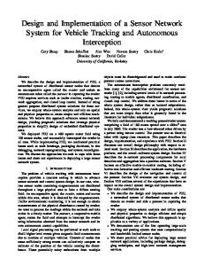
Fig. 1.
A block diagram of the proposed light emitting diode (LED) dimming system with multiple sensors controlled by a microcontroller. PWM: pulse width modulation.
general packet radio service (GPRS) is proposed [7]. If the LED lighting system is combined with a wireless sensor network and uses the location estimation method proposed in [8], the LED lighting system will become more intelligent than ever before. In this study, an intelligent LED dimming system, as shown in Fig. 1, is designed and implemented using an LED driver circuit and multiple sensors—light intensity and ultrasonic range sensors—and is controlled by a microcontroller.
Fig. 2. Photographs of (a) Stellaris microcontroller development board, (b) Supertex LED driver board, (c) ultrasonic range sensor and light intensity sensor, and (d) LED light bulb (inset shows the LED chips inside the light diffuser). Note that these photographs are not to scale. LED: light emitting diode. LED dimming without manual control can be realized by integrating sensors into the LED dimming system. In this work, two different sensors—a light intensity sensor and ultrasonic range sensor—are used. The light intensity sensor monitors the ambient light intensity around the LED lighting. The ultrasonic range sensor provides sonar range information for the microcontroller to control the brightness of the LED light bulb. In this work, a Stellaris microcontroller, LM3S9D96 [9] manufactured by Texas Instruments, is used for implementing the LED dimming system. A 32-bit microcontroller is used in this work since more intelligent functions, for example, wired light control (that is, digital addressable lighting interface [DALI]), wireless light control (ZigBee or Bluetooth), and visual light communication, can be implemented in a future work. For the LED driver, a Supertex LED driver, HV9910B [10], is used for
II. DESIGN OF LED DIMMING SYSTEM For the development of an intelligent LED dimming system controlled by a microcontroller, certain hardware and software design techniques are required.
A. Hardware Design As shown in Fig. 1, a microcontroller, an LED driver, and a variety of sensors are required to implement the proposed LED dimming system. Basically, the brightness of LEDs can be adjusted by controlling the forward current through the LEDs. There are two possible ways to dim LEDs: analog dimming and digital dimming. Analog dimming is achieved by adjusting the forward current linearly through the LEDs using a data converter, such as an analog-to-digital converter (ADC) or a digital-to-analog converter. On the other hand, digital dimming is commonly used because of its easy implementation and the improved LED driver efficiency. A simple, widely used method of digital dimming is dimming with a pulse width modulation (PWM) signal. The forward current through the LEDs can be adjusted by changing the duty cycle of the PWM signal; this results in controlling the brightness of the LEDs. Many microcontrollers available on the market today are capable of generating PWM signals.
http://dx.doi.org/10.6109/jicce.2013.11.4.247
Table 1. Major components and their manufacturers Component
Manufacturer
Part number
Microcontroller LED driver
Texas Instruments Supertex LIDA Optical & Electronic Co., Ltd.
LM3S9D96 HV9910B
MaxBotix Inc.
MB1010
Light intensity sensor Ultrasonic range sensor
248
GL5528
Design and Implementation of LED Dimming System with Intelligent Sensor Module
Fig. 3.
Overall design architecture of the control software. ADC: analogto-digital converter, PWM: pulse width modulation.
Fig. 4.
(a)
(b)
Two main software modules: (a) interrupt service routine for reading the ultrasonic range sensor and (b) controller routine that adjusts the duty cycle of the pulse width modulation (PWM) signals. ADC: analogto-digital converter.
generating power for a 7-W 2-chip LED light bulb. The Stellaris microcontroller is connected to the LED driver and controls the output current of the LED driver by changing the duty cycle of the PWM signals. For the light intensity sensor, a CdS photoconductive cell, GL5528 [11] manufactured by LIDA Optical & Electronic Co., Ltd., is used. For the ultrasonic range sensor, a highperformance sonar range finder, MB1010 [12] manufactured by MaxBotix Inc., is used. It provides sonar range information from 6 inches (0.15 m) to 254 inches (6.45 m) at a resolution of 1 inch (0.0254 m). A 7-W 2-chip LED light bulb is fabricated using two LED chips, a heat sink, and a light diffuser in the lab at Wonkwang University. Each LED chip consumes 832 mA at 8.6 V when the duty cycle of the PWM signal is 100%. Photographs of the microcontroller, LED driver, sensors, and LED light bulb are shown in Fig. 2(a), (b), (c), and (d), respectively. The major components and their manufacturers are listed in Table 1. The various PWM signals generated by the microcontroller and the current consumption of the LED light bulb with respect to the duty cycle of the PWM signal will be discussed in the next section.
1) Control of ultrasonic range sensor For reading the ultrasonic range sensor and calculating the distance from the raw sensor value, the following algorithm is implemented in the actual code: (1) Initialize the ADC interrupt. ① Enable the ADC. ② Enable GPIO port B. ③ Configure Pin 4 of GPIO port B. ④ Configure the ADC sample sequence to read a voltage from the pin. ⑤ Enable the ADC sample sequence interrupt. (2) Implementation of an ADC interrupt handler. ① Clear the ADC sample sequence interrupt. ② Read a raw ADC value. ③ Convert the raw value to millivolts using the equation Or × VCC × 1,000/Rmax, where Or denotes the raw output value; VCC, the input voltage; and Rmax, the maximum resolution value. ④ Update current millivolt value that will be used for changing the PWM duty cycle to change the brightness of the LED light bulb on the basis of the measured distance. See “3) Control of duty cycle of PWM signals” for more details.
B. Software Design The software implementation for controlling the LED dimming system is as follows: ADC interrupts are used for converting the analog input from the light intensity sensor and the ultrasonic range sensor into a digital value. Timer1 in the microcontroller is used for generating PWM signals. The output of the light intensity sensor and the ultrasonic range sensor is read periodically. In this system, a polling method is used for the sake of simplicity. Fig. 3 shows the overall control structure.
The distance from an output voltage of the ultrasonic sensor can be calculated as follows: VCC is 3.3 V in the Stellaris board. The voltage resolution of the sensor is 512, which means VCC can be evenly divided by 512. The unit millivolt (mV) for an inch can be calculated by dividing 3,300 mV by 512 (= 6.45 mV). Therefore, the output voltage of the ultrasonic range sensor can be used for measuring the distance by dividing the raw voltage by the
249
http://jicce.org
J. lnf. Commun. Converg. Eng. 11(4): 247-252, Dec. 2013
unit voltage. For example, if the output voltage of the ultrasonic range sensor is 500 mV, the distance will be 500 mV/6.45 = 77.52 inches. The light intensity sensor can be controlled by a similar algorithm for the ultrasonic range sensor. 2) Generation of PWM signals As mentioned previously, Timer1 in the microcontroller is used for generating PWM signals. The following algorithm is implemented in the actual code: (1) Initialize the board. ① Set the clock to run directly from the external crystal/oscillator. A 16-MHz crystal is used. ② Enable the Timer1 peripheral. ③ Enable GPIO port E. (2) Configure the timer. ① Configure the GPIO pin muxing for the Timer/ CCP function. ② Configure the CCP setting for CCP3. Pin 4 of GPIO port E is used. ③ Configure Timer1 as a 16-bit periodic timer. ④ Set the Timer1 value to 50,000.
Fig. 5.
Experimental setup for the light emitting diode (LED) dimming system. The inset shown in the upper left of the photograph is the top view of the experimental setup.
3) Control of duty cycle of PWM signals The following algorithm is implemented in the actual code to control the duty cycle of the PWM signals. (1) Disable Timer1. (2) Read current timer load value Lt that was set to 50,000 in this algorithm. (3) Acquire distance information from the ultra-sonic range sensor. See “1) Control of ultrasonic range sensor” for more details about acquiring distance information from the ultrasonic range sensor. (4) Acquire the on-duty percentage óon from dcur/dmax where dmax denotes the maximum distance to measure and dcur represents the current distance information. (5) Set the timer with Lt × (1 - óon). (6) Enable the timer.
(a)
(b)
Fig. 4(a) and (b) show the overall procedures of these two software modules.
III. RESULTS A. Setup of LED Dimming System In this work, the Stellaris microcontroller development board from TI is used for simplifying the hardware development process. To the microcontroller development board, the ultrasonic range sensor and the light intensity sensor are connected through analog interface ports of the microcontroller.
http://dx.doi.org/10.6109/jicce.2013.11.4.247
(c)
Fig. 6. The pulse width modulation (PWM) signals generated by the microcontroller at the three different positive duty cycles: (a) 1/16 = 6.25%, (b) 8/16 = 50%, and (c) 15/16 = 93.75%.
250
Design and Implementation of LED Dimming System with Intelligent Sensor Module
10
800 700 Voltage
500
8
400
7
300 6
200 100
Voltage (V)
Current (mA)
9
Current
600
(that is, 256 levels). In order to quantify the LED dimming level with respect to the duty cycle of the PWM signal, the current consumption by the 2-chip LED light bulb is measured and shown in Fig. 7. The voltage at the input of the LED light bulb is also measured. It is clearly shown that the LED dimming level is controlled linearly by the duty cycle of the PWM signals. This linear characteristic is essentially the performance of the LED dimming system, since it allows the fine dimming range controlled by the microcontroller through PWM signals.
5
0 0
20
40
60
4 100
80
Duty cycle (%)
C. Control of Multiple Sensors by Software
Fig. 7.
Current consumption by the 2-chip light emitting diode (LED) light bulb and the input voltage at the 2-chip LED light bulb with respect to the duty cycle of the pulse width modulation signals.
As an example of the software algorithm, Fig. 8 shows the duty cycle of the PWM signals generated by the microcontroller with respect to the measured distance from the LED light bulb by the ultrasonic range sensor. In the driver software, there is a look-up table for the duty cycle versus the distance from the LED light bulb. When the ultrasonic range sensor detects an object, the microcontroller calculates the distance between the LED light bulb and the object and generates a PWM signal according to the look-up table. As shown in Fig. 8, the generated duty cycle is almost the same as the duty cycle in the look-up table in the driver software. At a distance of more than 5.6 m, the microcontroller generates a duty cycle of 98% because of the limitation of the ultrasonic range sensor. Although the manufacturer specifies that the maximum detectable distance is 6.45 m, the actual distance measured by the sensor in the experiment is 5.6 m. This produces the difference between the generated duty cycle and the duty cycle in the look-up table as shown in Fig. 8.
100
Duty cycle (%)
80
Generated by microcontroller Look-up table
60 40 20 0
0
1
2
3
4
5
6
7
Distance (m)
Fig. 8. Duty cycle of the pulse width modulation signals with respect to the distance measured by the ultrasonic range sensor.
An LED driver board generating stable power for the 2chip LED light bulb is connected to the microcontroller development board that provides PWM signals. The LED dimming system described above is shown in Fig. 5. For the sake of convenience, the top view of the LED dimming system is shown in the inset of Fig. 5.
IV. CONCLUSIONS Using a microcontroller with multiple sensors—light intensity sensors and ultrasonic range sensors—in this work, we have designed and implemented an intelligent LED dimming system. Further, a 256-level LED dimming system is realized by controlling the duty cycle of PWM signals from the microcontroller. When the LED dimming function is combined with the multiple sensors that provide the distance information from any objects and the ambient light intensity around the LED light bulb, the brightness of the LED is automatically controlled. The proposed intelligent LED dimming system can work together with a wired and/or wireless network interface to realize ubiquitous LED lighting systems.
B. Performance of LED Dimming The various PWM signals from the microcontroller are shown in Fig. 6. PWM signals with the positive duty cycles of 6.25%, 50%, and 93.75% are shown in Fig. 6(a), (b), and (c), respectively. The frequency of the PWM signals is set at 320 Hz, since the minimum output frequency is known to be 300 Hz for flicker-free LED dimming. As expected, the PWM signal at the very low duty cycle is a very narrow pulse as shown in Fig. 6(a). On the other hand, at the very high duty cycle shown in Fig. 6(c), the PWM signal is almost flat at the 3.3 V level. At the 50% duty cycle, the PWM signal is just a rectangular waveform. In this work, the LED dimming is implemented at a resolution of 8 bits
ACKNOWLEDGMENTS This research was supported by Basic Science Research
251
http://jicce.org
J. lnf. Commun. Converg. Eng. 11(4): 247-252, Dec. 2013
Program through the National Research Foundation of Korea funded by the Ministry of Education, Science and Technology (No. 2012R1A1A2040719).
[ 6 ] J. F. Wu, C. L. Wei, Y. T. Hsieh, C. L. Fang, H. H. Tsai, and Y. Z. Juang, “Integrated ambient light sensor on a LED driver chip,” in Proceeding of the IEEE International Conference on Power Electronics and Drive Systems, Singapore, pp. 944-947, 2011. [ 7 ] L. Lian and L. Li, “Wireless dimming system for LED street lamp
REFERENCES
based on ZigBee and GPRS,” in Proceeding of the 3rd IEEE International Conference on System Science, Engineering Design
[ 1 ] US Department of Energy, “Energy savings potential of solid state
and Manufacturing Informatization, Chengdu, China, pp. 100-102,
lighting in general illumination applications (final report),” US
2012.
Department of Energy, Washington, DC, 2006.
[ 8 ] C. H. Oh, “Location estimation enhancement using space-time
[ 2 ] S. G. Kini, “Design and development of energy efficient retrofit
signal processing in wireless sensor networks: non-coherent
LED fixture for solar powered home lighting system,” in
detection,” Journal of Information and Communication Conver-
Proceeding of the Annual IEEE India Conference, Hyderabad,
gence Engineering, vol. 10, no. 3, pp. 269-275, 2012.
India, 2011.
[ 9 ] Texas Instruments, Stellaris LM3S9D96 microcontroller datasheet
[ 3 ] B. S. Seo, K. J. Lee, J. K. Yang, Y. S. Cho, and D. H. Park,
[Internet]. Available: http://www.ti.com/product/lm3s9d96.
“Development and characterization of optimum heat sink for 30 W
[10] Supertex Inc., Universal high brightness LED driver: HV9910B
chip on board LED downlight,” Transactions on Electrical and
datasheet [Internet]. Available: http://www.supertex.com/pdf/data
Electronic Materials, vol. 13, no. 6, pp. 292-296, 2012.
sheets/HV9910B.pdf.
[ 4 ] D. Liu, D. G. Yang, R. Ren, F. Hou, and C. Huang, “Reliability
[11] LIDA Optical and Electronic Co. Ltd., CdS photoconductive cells:
study on high power LED with chip on board,” in Proceeding of
GL5528 [Internet]. Available: http://mdfly.com/Download/Sensor/
the 12th IEEE International Conference on Electronic Packaging
PD0001.pdf.
Technology & High Density Packaging, Shanghai, China, pp.
[12] MaxBotix Inc., LV-MaxSonar-EZ1 high performance sonar range
1004-1007, 2011.
finder [Internet]. Available: http://www.maxbotix.com/documents/
[ 5 ] A. Suzdalenko and I. Galkin, “Choice of power and control
MB1010_Datasheet.pdf.
hardware for smart LED luminary,” in Proceeding of the 12th IEEE Biennial Baltic Electronics Conference, Tallinn, Estonia, pp. 331-334, 2010.
was born in Iksan, Korea. He received his B.S. and M.S. in Electrical and Telecommunications Engineering from Hanyang University, Seoul, Korea, in 1996 and 1998, respectively, and his Ph.D. in Electrical Engineering from the University of Minnesota, Minneapolis, MN, USA, in 2010. In 1998, he joined SK Telecom, Seoul, where he was with Strategic Planning for Intelligent Terminal Manufacturing R&D as an Assistant Researcher. From 1998 to 2004, he was a Researcher with the R&D Center, SK Teletech, Seoul, where he was involved in the development of CDMA cellular phones. His research interests include microwave and millimeter-wave circuits, mixed RF/photonic packaging, micromachining, and the development of sensor networks.
was born in Yeongyang, Korea. He received his B.S. and M.S. degrees from Hanyang University, Seoul, Korea, in 1992 and 1994, respectively, and his Ph.D. degree in Computer Engineering from the Texas A&M University, College Station, TX, in 2009. He is currently with Kettering University, MI, USA. From 1994 to 1999, he worked for LG Electronics, Seoul, where he worked in Media Communication Research Center as a software engineer. From 2000 to 2002, he worked as a software engineer in the R&D Center of SK Teletech, Seoul, Korea, where he was involved in the development of CDMA cellular phones. From 2002 to 2004, he was a senior software engineer in Qualcomm Korea. His research interests include artificial intelligence, computational neuroscience, embedded system software, and embedded application platforms.
received his B.S. in Electrical Engineering from Chonbuk National University, Korea, in 1973. He received his M.S. and Ph.D. degrees from Chonbuk National University in 1978 and 1984, respectively. He is currently with the Department of Electronic Engineering, Wonkwang University, Iksan, Korea, as a faculty member. His research interests include system-on-chip design, embedded systems, and signal processing.
http://dx.doi.org/10.6109/jicce.2013.11.4.247
252