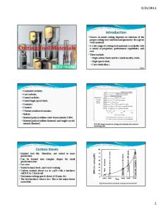
Definition ultra hard cutting materials
The term ultra hard cutting materials describes all cutting materials that are classified above carbides, cermets and cutting ceramics on the hardness scale. Within this definition, it is possible to differentiate between two groups:
Diamond cutting materials PCBN substrates
Diamond cutting materials can be split into two main groups, monocrystalline and polycrystalline, whereby polycrystalline is then split into a further two subgroups. Monocrystalline diamonds are used in finishing and superfinishing processes. Optimum surfaces and maximum geometric accuracies for the components are the focus here. High chip volume is secondary to these criteria. Polycrystalline diamond cutting materials, PCD and CVD-D differ primarily in terms of how they are manufactured and their structure. PCD describes a cutting material group in which the diamonds are sintered as grains in a metal matrix. Each individual grain is itself monocrystalline. Different properties are produced due to the variation of the grains. CVD-D (chemical vapour deposition) is deposited from the gas phase. The suffix "D" stands for thick film and is used to differentiate it from conventional diamond coating. Thick film describes the thickness (0.3 - 1 mm) of the cutting material that is soldered to the carbide toolholder for further processing. PCBN (polycrystalline cubic boron nitride) substrates have different properties due to their composition. These are configured specifically for the application
10000 8000 6000 Scattering range
4000 2000
min.
SS H
de C
ar bi
ic am er C
D
PC BN
m ia D al ur
at N
PC
on
d
C C M
C D M
VD
-D
0
C
Hardness Vickers (HV)
ultra hard cutting materials
Anwendung hochharter Schneidstoffe Application of ultra hard cutting materials
Die richtige Anwendung ist entscheidend, um das große Potential der CBN- und Diamantschneidstoffe in der Fertigung optimal zu nutzen. Die große Härte des Diamanten in seinen unterschiedlich angebotenen Formen wie PKD, MKD, CVD-D oder Naturdiamant und der daraus resultierenden Schneidenschärfe verlangen ein teilweise anderes Herangehen an die jeweilige Zerspanungsaufgabe, als mit herkömmlichen Schneidstoffen. Die hohe Warmbeständigkeit in Verbindung mit der hohen Härte, die zweithöchste nach Diamant, macht CBN (polykristallines kubisches Bornitrid) zum idealen Schneidstoff für die Bearbeitung von gehärteten Stählen. Die unterschiedlichen CBN-Substrate variieren in Zusammensetzung und der daraus resultierenden mechanisch-chemischen Eigenschaften. Neben der Zerspanung von gehärteten Stählen (45-70 HRC) eignet sich diese Schneidstoffgruppe auch hervorragend zur Bearbeitung von Gusswerkstoffen und Sonderlegierungen, bei denen Hartmetall und Schneidkeramik an ihre Grenzen kommen. Die verschiedenen hochharten Schneidstoffe sind entsprechend Ihrer Zusammensetzung bzw. ihrem Aufbau für unterschiedliche Aufgaben optimiert. Daher ist die richtige Sortenwahl in Kombination mit der passenden Schneidengeometrie von größter Bedeutung. Die empfohlenen Schnittparameter sind die Eckdaten, innerhalb derer ein wirtschaftliches Ergebnis und/oder Spanbruch erziehlt werden kann. In jedem Fall ist eine Anpassung der Parameter an die gesamte Zerspansituation vorzunehmen. Um bestmögliche Ergebnisse zu erzielen, muss das gesamte Maschinenumfeld beachtet und auf ein möglichst hohes Stabilitätsniveau gebracht werden. Der Aufbau der Maschine, Führungen, Spindeln und die Spannsysteme für Werkstück und Werkzeuge haben einen entscheidenden Einfluss auf das Ergebnis.
Choosing the right application is crucial when it comes to maximising the huge potential of PCBN and diamond cutting materials in manufacturing. The high level of hardness of diamond in its various forms such as PCD, MCD, CVD-D or natural diamond and the resulting cutting edge sharpness may mean that a different approach to the one taken with conventional cutting materials may be required depending on the machining task in question. Its high heat resistance combined with the high level of hardness, which is second only to diamond, makes PCBN (polycrystalline cubic boron nitride) the ideal cutting material for machining hardened steels. The different PCBN substrates vary in terms of their composition and the resulting mechanical and chemical properties. In addition to the machining of hardened steels (45-70 HRC), this cutting material group is also highly suited to the machining of cast materials and special alloys – an application where carbides and cutting ceramics often reach their limits. The composition and/or structure of the various ultra-hard cutting materials are optimised for different tasks. Therefore, it is extremely important that the right type of cutting material in combination with the right cutting geometry is selected. The recommended cutting parameters are the key data that enable an efficient result and/or chip break to be achieved. In each case, it is necessary to adapt the parameters to the machining situation as a whole. In order to achieve the best results possible, the entire machine environment must be taken into account and brought to the highest level of stability possible. The structure of the machine, guides, spindles and the clamping systems for the workpiece and tools play a key role with respect to the result.
A
CVD-D, das Maximum an Härte CVD-D, maximum strength
Die Verschleißfestigkeit von CVD-D übertrifft die von PKD deutlich. Grund hierfür ist die nicht vorhandene, metallische Bindefase und der daraus resultierende Diamantanteil von nahezu 100 Prozent. Einzelne, monokristalline Diamantkörner werden aus Gas abgeschieden und verwachsen untrennbar miteinander zu einer soliden, polymeren Diamantschicht. Das Verfahren ähnelt der Diamantbeschichtung von Hartmetallwerkzeugen, jedoch ist dort die Schichtstärke nur wenige µm dick und somit nach relativ kurzer Einsatzdauer abgetragen. Neben der maximalen Härte kommen noch andere, positive Eigenschaften von Diamant dem Zerspanungsprozess zugute. Die besondere Wärmeleitfähigkeit sorgt für einen kühlen Schnitt. Der geringe Reibungskoeffizient und eine geringe Adhäsionsneigung verhindert zuverlässig eine Aufbauschneidenbildung. Selbst bei kritischen Aluminiumknetlegierungen kann ohne Einsatz von Kühlschmierstoff, prozesssicher zerspant werden. Lasertechnologie ist bei der Fertigung von CVD-D bestückten Schneiden unverzichtbar. Die hohe Schneidenqualität und das Einbringen von Spanformgeometrien wären ohne diese Technologie schlichtweg nicht möglich. Die erreichbaren Oberflächengüten sind grundsätzlich besser als die der von PKD erzeugten Schneiden. Lediglich die physikalisch bedingte, geringere Bruchzähigkeit schränkt den Einsatz etwas ein. Grundsätzlich ist der erreichbare Standweg, je nach Anwendung, der doppelte bis mehrfache vom Stand der PKD. The wear resistance of CVD-D significantly exceeds that of PCD. The reason for this is that it does not have a metallic binding chamfer and the fact that it has a resulting diamond component of almost 100 per cent. Individual, monocrystalline diamond grains are deposited from gas and grow together so that they cannot be separated to form a solid, polymeric diamond layer. The process is similar to the diamond coating of carbide tools but the layer thickness is just a few µm thick and is therefore worn away after a relatively short time in use. In addition to maximum hardness, other positive properties of diamond also benefit the machining process. Its special heat conductivity ensures cool cutting. The low coefficient of friction and a low adhesive tendency reliably prevent build-up edges from forming. Reliable machining processes can be performed even with critical aluminium wrought alloys without using cooling lubricant. Laser technology is indispensable when it comes to manufacturing CVD-D cutting edges. It would simply be impossible to achieve the high cutting quality and apply chip shape geometries without this technology. The surface qualities that can be achieved are significantly better than those of cutting edges produced from PCD. Only its lower fracture toughness, which is due to its physical properties, limits the use of the material to some extent. The achievable tool life is double or several times that of tools manufactured from PCD.
A2
A
PKD ist nicht gleich PKD Not all PCD is the same
PKD ist ein Verbundschneidstoff. Diamantkörner, jedes für sich monokristallin, sind in einer Metallmatrix, in der Regel Kobalt, miteinander versintert. Innerhalb des Sinterprozesses kommt es zu einem interkristallinen Kornwachstum, bei dem im begrenzten Umfang, die einzelnen Körner miteinander verwachsen und somit die Verschleißeigenschaften im späteren Einsatz positiv beeinflussen. Die Größe und Qualität der verwendeten Körner sind neben der Sintertechnologie Index für die Verschleißfestigkeit. Daraus leitet sich der theoretische Grundsatz ab „je größer das Korn, desto besser der Abrasionswiederstand". Jedoch leidet dadurch die erreichbare Schneidkantenqualität, Schartigkeit und Schärfe, unabhängig der zur Schneidkantenherstellung verwendeten Fertigungstechnologie. Auch der prozentuale Volumenanteil der metallischen Bindephase steigt und wirkt sich negativ aus. Das HORN-Hochleistung-PKD setzt sich aus einer ausgefeilten Mixtur unterschiedlicher Größen von Diamantkörnern zusammen. Der Volumenanteil von Diamant steigt, Wirkhärte, Zähigkeit und Schneidenqualität ebenso. Strenge Qualitätsstandards und deren Kontrolle sind selbstverständlich und sorgen für maximale Leistung.
PCD is a compound cutting material. Diamond grains, each one of a monocrystalline nature, are sintered to each other in a metal matrix, generally cobalt. During the sintering process, the grains grow within the crystals and the individual grains grow together to a limited extent, thereby affecting the wear properties during subsequent use. In addition to the sintering technology, the size and quality of the grains used are an indicator of wear resistance. It is possible to derive the following theoretical principle: "the larger the grain, the better the abrasion resistance". However, this compromises the cutting edge quality, chipping and sharpness that can be achieved, irrespective of the manufacturing technology used to produce the cutting edges. The percentage volume fraction of the metallic binding phase also increases and has a negative effect. HORN high-performance PCD is comprised of a sophisticated mixture of different diamond grain sizes. The volume fraction of diamond increases, as do effective hardness, toughness and cutting quality. It goes without saying that strict quality standards are observed and monitored and ensure maximum performance.
A3
SCHNITTDATEN CVD CUTTING DATA CVD Eckfräsen
Shoulder milling ae x Ø (mm)
Ø3
Ø4
Ø6
Ø8
Ø 10 Ø 12 Ø 16 Ø 20
0,65
0,40
0,02
0,02
0,03
0,05
0,10
0,10
0,12
0,15
0,20
Gleichlauf Climbing
0,60
0,30
0,01
0,02
0,02
0,04
0,10
0,08
0,10
0,13
0,18
Gleichlauf / Climbing
800
0,50
0,25
0,01
0,01
0,02
0,03
0
0,06
0,08
0,10
0,15
Gleichlauf / Climbing
PMMA (Acryl)
1100
0,50
0,50
0,01 0,015 0,02
0,03
0,05
0,07
0,09
0,12
0,15
Gleichlauf / Climbing
PA66 CF/GF 30
700
0,50
0,30 0,008 0,01 0,015 0,025 0,04
0,06
0,08
0,10
0,12
Gegenlauf / Conventional
PEEK CF/GF30
700
0,50
0,25 0,007 0,008 0,01
0,03
0,05
0,07
0,08
0,10
Gegenlauf / Conventional
POM CF/GF30
800
0,50
0,50 0,008 0,01 0,015 0,025 0,04
0,06
0,08
0,10
0,12
Gegenlauf / Conventional
PTFE CF/GF30
700
0,50
0,30
0,01 0,015 0,02
0,03
0,05
0,07
0,09
0,12
0,15
Gegenlauf / Conventional
GFK
500
0,50
0,30
0,01 0,015 0,02
0,03
0,05
0,07
0,09
0,12
0,15
Gegenlauf / Conventional
CFK
250
0,40
0,25 0,008 0,01 0,015 0,025 0,04
0,06
0,08
0,10
0,12
Gegenlauf / Conventional
SFK/AFK (Armid)
300
0,45
0,30
0,01 0,015 0,02
0,03
0,05
0,07
0,09
0,12
0,14
Gegenlauf / Conventional
Zirkonium
150
0,50
0,40
0,01
0,04
0,10
0,08
0,10
0,13
0,18
Gleichlauf / Climbing
vc (m/min)
N
Vorschub Richtung
Ø2
Material
AlSi (< 6 %)
3000
AlSi (>6 - 12 %)
1800
AlSi (>12 %)
0,02
0,02
0,02
Feed rate direction
empfohlene Kühlung recommended cooling
Emulsion MMS Emulsion MMS
Emulsion Emulsion
trocken / Pressluft zum Entfernen der Späne dry / Air pressure to remove chips
Kopierfräsen Copy milling
ae x Ø (mm)
Vorschub Richtung
Ø2
AlSi (< 6 %)
3000
0,25
0,15
0,02
0,10
0,10
0,12
0,10
0,20
Gleichlauf / Climbing
AlSi (>6 - 12 %)
1800
0,20
0,10 0,001 0,002 0,002 0,004 0,10
0,08
0,10
0,13
0,18
Gleichlauf / Climbing
AlSi (>12 %)
1100
0,15
0,10
0,01
0,02
0,03
0
0,06
0,08
0,10
0,15
Gleichlauf / Climbing
PMMA (Acryl)
1100
0,15
0,15
0,01 0,015 0,02
0,03
0,05
0,07
0,09
0,12
0,15
Gleichlauf / Climbing
PA66 CF/GF 30
700
0,15
0,10 0,008 0,01 0,015 0,025 0,04
0,06
0,08
0,10
0,12
Gegenlauf / Conventional
PEEK CF/GF30
700
0,15
0,10 0,007 0,008 0,01
0,03
0,05
0,07
0,08
0,10
Gegenlauf / Conventional
POM CF/GF30
800
0,15 0,015 0,008 0,01 0,015 0,025 0,04
0,06
0,08
0,10
0,12
Gegenlauf / Conventional
PTFE CF/GF30
700
0,15
0,10 0,001 0,015 0,02
0,03
0,05
0,07
0,09
0,12
0,15
Gegenlauf / Conventional
GFK
500
0,15
0,10
0,03
0,05
0,07
0,09
0,12
0,15
Gegenlauf / Conventional
CFK
250
0,15
0,10 0,008 0,01 0,015 0,025 0,04
0,06
0,08
0,10
0,12
Gegenlauf / Conventional
SFK/AFK (Armid)
300
0,15
0,10
0,01 0,015 0,02
0,03
0,05
0,07
0,09
0,12
0,14
Gegenlauf / Conventional
Zirkonium
150
0,15
0,15
0,01
0,04
0,10
0,08
0,10
0,13
0,18
Gleichlauf / Climbing
Material
N
Vorschub / Feed rate fz (mm)
ap x Ø (mm)
Werkstoff vc (m/min)
C
Vorschub / Feed rate fz (mm)
ap x Ø (mm)
Werkstoff
C10
Feed rate direction
Ø3
Ø4
Ø6
Ø8
Ø 10 Ø 12 Ø 16 Ø 20
0,02
0,03
0,05
0,01
0,01 0,015 0,02
0,02
0,02
0,02
empfohlene Kühlung recommended cooling
Emulsion MMS Emulsion MMS
Emulsion Emulsion
trocken / Pressluft zum Entfernen der Späne
dry / Air pressure to remove chips
Oberflächengüte Surface quality
Oberflächengüte in Abhängigkeit von Schneidenradius und Vorschub. Wählen Sie den größtmöglichen Schneidenradius, den Systemsteifigkeit, Werkstückkontur und Spankontrolle erlauben. Surface quality in relation between edge radius and feed rate. Choose the maximal edge radius of which system stability, workpiece shape and chip controll allows.
f
Werte in µm
r
Rt
Data's in µm
Rt =
f2 8xr
r =
f2 8 x Rt
f = 8 x r x Rt
theoretisch erreichbare Oberflächengüte theoretical surface quality Ra (µm) Rt (µm)
0,4 - 0,8 1,6
0,8 - 1,6 4
0,04 0,05 0,7 0,10 0,12
0,05 0,70 0,09 0,17 0,20
Radius
Radius
0,1 0,2 0,4 0,8 1,2
J
1,6 - 3,2 3,2 - 6,3 10 16 fn (mm/U) fn(mm/rev) 0,07 0,10 0,10 0,14 0,15 0,22 0,22 0,27 0,25 0,34
Oberflächengüte mit Wiper-Geometrie Surface quality with Wiper-Geometry
f
r
J4
Rt 3-4
6,3 - 12,5 28
12,5 - 25 40
0,12 0,18 0,25 0,35 0,43
0,18 0,45 0,35 0,50 0,60
Wiper Geometrien Wiper Geometries
Für die Hochleistungszerspanung haben wir für das Innen- und Außendrehen eine große Anzahl von Plattentypen mit WIPER Geometrie entwickelt. Diese besitzen eine Schleppschneide zwischen Radiusauslauf und seitlicher Schneidkante, die wie eine Nebenschneide mit 0° Anstellwinkel wirkt. Selbst bei einem 2 - 4 fach höherem Vorschub werden dieselben Oberflächengüten erreicht. Durch die Reduzierung der Bearbeitungszeit, der optimalen Spankontrolle und der Standzeiterhöhung steigern Sie die Produktivität in erheblichem Ausmaß bei gleichzeitiger Kostensenkung. Bitte beachten Sie beim Einsatz der Wiper Geometrien: Der Anstellwinkel muss genau eingehalten werden, da sonst der gewünschte Schleppschneiden Effekt nicht eintritt und keine guten Oberflächen erreicht werden: CCGW / T = 95 ° DCGW / T = 93° Beachten Sie die Schneidrichtung, da die Wiper Geometrien durch die Schleppschneide richtungsgebunden sind. Nur so können die gewünschten Oberflächengüten und ein optimaler Spanfluss erreicht werden. Beim Plandrehen immer vom großen zum kleinen Durchmesser bearbeiten! Durch die geometrische Auslegung der Schneide kommt es zu Konturverzerrungen bei Radien, Fasen, Schrägen und Freistichen! Vorteile der Wiper Geometrien: ● ● ● ●
Bessere Oberflächengüten bei gleichen Bearbeitungsparametern Höhere Vorschübe - Schruppen und Schlichten mit einer Platte möglich Besserer Spanbruch durch höhere Vorschübe Höhere Vorschübe reduzieren die Eingriffszeit pro Teil und dadurch das Verschleißverhalten und erhöhen die Standzeiten erheblich
For the purpose of high performance cutting in the fields turning and milling, we developed a large number of inserts with WIPER geometry. Those geometries are designed with a trailing edge between edge radius and lateral cutting edge, which works like a cutting edge with 0° approach angle. Even with 2 - 4 times higher feed rates you can achieve the same surface qualities. Through reduction of cycle time, the optimal chip control with higher federates and the increase of tool life, you can escalate your productivity while reducing costs at the same time. Please keep in mind when using Wiper Geometries: The approach angle needs to be applied accurately, in order to achieve the desired wiper effect to get best surface qualities: CCGW / T = 95 ° DCGW / T = 93° Be aware of the cutting direction. Wiper geometries are designed to trail behind the cutting edge for proper chip flow and surface quality. Facing operations should always be performed form the larger to smaller diameter. Because of the trailing edge, distortion can occur on radii, chamfers and tapers. Advantages of Wiper Geometries: ● ● ● ●
Better surface qualities at the same cutting parameters Higher feed rates - Roughing and finishing with one insert is possible Better chip control through higher feed rates Higher feed rates reduces the cutting time per workpiece and therefore the wear characteristic and this leads to significantly longer tool life
J5
J
Wuchten Balancing
Von einer Unwucht spricht man bei rotierenden Körpern, deren Masse nicht rotationssymmetrisch verteilt ist. In anderen Worten bedeutet dies, dass die Massenträgheitsachse von der Rotationsachse abweicht. ... Quelle: http://de.wikipedia.org/wiki/Unwucht Aufgrund der hohen Umdrehungszahlen moderner Werkzeugspindeln sollten die eingesetzten Werkzeuge mit ihren Aufnahmen gewuchtet werden. Ansonsten leiden die erreichbaren Oberflächengüten und die Standzeiten der Werkzeuge. Besonders in der Glanz- und Hochglanzbearbeitung kann dies entscheidend für ein perfektes Ergebnis sein. Bei großen Massen und/oder großen Durchmessern sind die Effekte der Unwucht auch bei relativ geringen Drehzahlen zu beachten. Man unterscheidet die statische Unwucht sowie die dynamische Unwucht. Bei der statischen Unwucht liegt der Schwerpunkt des Rotors außerhalb der Drehachse. Bei kurzen Werkzeugen kann kein hohes Moment zustande kommen. Daher genügt hier häufig das Wuchten in einer Ebene (statisch). Grundsätzlich werden unsere Werkzeuge schon innerhalb der Konstruktion mittels CAD wuchtgerecht konstruiert. Faktisch bedeutet das die Betrachtung der Massenverhältnisse und deren Ausgleich in der Theorie. Dies ist ein Qualitätsmerkmal und eine Maßnahme zur Erreichung der gewünschten Wuchtgüte ohne zusätzlichen Aufwand. Das Wuchten des Gesamtsystems kann diese Maßnahme jedoch nicht ersetzten.
Drehachse
Schwerpunktachse
Axis of rotation
Priority axis
e achs Drehof rotation
Schwerpunktachse Priority axis
Axis
Statische Unwucht
J
Static unbalance
Dynamische Unwucht Dynamic unbalance
Rotating Unbalance is the uneven distribution of mass around an axis of rotation. Unbalance is caused when the centre of mass (inertia axis) is out of alignment with the centre of rotation (geometric axis).... source: http://de.wikipedia.org/wiki/Unwucht The high speeds associated with state-of-the-art tool spindles mean that the tools used need to be balanced with their supports. Failure to do this has an impact on the surface qualities that can be achieved as well as on tool life - this can be crucial when it comes to achieving a perfect result, particularly with respect to polishing and brilliant finish machining. With large masses and/or large diameters, the effects of any unbalance must be taken into account even when working at relatively low speeds. A distinction is drawn between static unbalance and dynamic unbalance. Static unbalance occurs when the rotor's centre of gravity is outside the rotary axis. With short tools, high torque values cannot develop meaning that balancing in one plane is often sufficient here (static). Our tools are designed to be balanced at the CAD stage. In practice, this means that the mass ratios and their offsets are considered during the theoretical design phase. This is a feature that demonstrates our quality and is a way of achieving the required balance without the need for additional work. Nevertheless, this measure does not replace the need to balance the system as a whole.
J6
Diamantschneidstoffe Diamond cutting materials HORNSorten MD10
Schneidstoff
MKD
Eigenschaften
Anwendungsgebiete
Monokristalliner Diamant ohne Gefüge, höchste Härte absolut scharfe und schartenfreie Schneidkanten, geringe Bruchzähigkeit
Glanz- und Hochglanzbearbeitung aller NE Metalle, Kunststoffe ohne abrassive Füllstoffe, Edelmetalle und deren Legierungen
CVD Dickschicht Diamant (Polykristallines Diamantsubstrat) ohne Hartmetallunterlage und ohne metallische Bindephase, 99,5% Diamantanteil, höchste Verschleißfestigkeit scharfe, schartenfreie Schneidkanten, geringere Bruchzähigkeit
Bearbeitung aller NE Metalle, Aluminium Legierungen, Kunststoffe mit abrassiven Füllstoffen, EdelmetallLegierungen, Hartmetall, Keramikgrünlinge
HD03 HD05 HD08
CVD-D
PD70
PKD
Polykristalliner Diamant, Mischkorn mit Hartmetallunterlage, gute Schneidenschärfe, höchste Verschleißfestigkeit und gute Zähigkeit
Bearbeitung von NE-Metallen und Kunststoffen mit Anteilen abrassiver Füllstoffe, Schlichten bis Schruppen
PD75
PKD
Polykristalliner Diamant, Feinkorn mit Hartmetallunterlage, sehr gute Schneidenschärfe, verbesserte Verschleißfestigkeit und Zähigkeit
Bearbeitung von NE-Metallen und Kunststoffen mit Anteilen abrassiver Füllstoffe, Feinschlichten und Schlichten bis Schruppen
Properties
Recommended applications
MCD
Solid Monocrystalline Diamond without grain structure, highest hardness, absolutely sharp cutting edge without micro fractures, low toughness
Polish and high polish machining of all nonferrous metals, plastics without abrassive reinforcements, precious metals and precious alloys
CVD-D
CVD Diamond (Polycrystalline Diamond substrate) without solid carbide material and without metallic binder. 99.5% Diamond, Highest hardness and wear resistance, sharp cutting edge without micro fractures, improved toughness
Machining of all nonferrous metals, Aluminium alloys, Plastics with abrassive reinforcements, precious alloys, Solid Carbide, Ceramic green parts
PD70
PCD
Polycrystalline Diamond, mixed grain solid carbide reinforced, fine grit size, good cutting edge sharpness, highest wear resistance and toughness
All purpose for all nonferrous metals and plastics with abrassive reinforcements, from finishing to roughing
PD75
PCD
Polycrystalline Diamond, micro grain solid carbide reinforced, fine grit size, very good cutting edge sharpness, improved wear resistance and toughness
All purpose for all nonferrous metals and plastics with abrassive reinforcements, ultra fine finishing and from finishing to roughing
HORNGrades MD10
HD03 HD05 HD08
Cutting material
J7
J
Bezeichnung der Schneidstoffe nach DIN ISO 513 (2001) Description of cutting materials according DIN ISO 513 (2001)
MKD / MCD Monokristalliner Diamant Monocrystalline Diamond
CVD - D Polykristalliner Diamant Polycrystalline Diamond
Verschleißfestigkeit / Wear resistance
PKD / PCD Polykristalliner Diamant Polycrystalline Diamond
BC beschichtetes CBN coated CBN
BH CBN 70 -95% PCBN 70 - 95%
BL CBN 40 - 65% PCBN 40 - 65%
Schneidkeramik Ceramic
J
beschichtete HM-Sorten Cermet
coatet grades
Cermet
Feinkorn Hartmetall beschichtet / unbeschichtet Micro grain carbide coated / uncoated
unbeschichtetes Hartmetall uncoated grades
Zähigkeit / Toughness
J8