Component-Based Methodology and Development Framework for Virtual and Augmented Reality Systems
THÈSE No 3046 (2004) PRÉSENTÉE A LA FACULTE INFORMATIQUE ET COMMUNICATIONS Institut des systemès informatiques et multimèdias SECTION D’INFORMATIQUE
ÉCOLE POLYTECHNIQUE FÉDÉRALE DE LAUSANNE PUR L’OBTENTION DU GRADE DE DOCTEUR ÈS SCIENCES PAR
Michal PONDER M.Sc. in Applied Physics, Warsaw University of Technology, Warsaw, Pologne B.Sc. in Physics, Brunel University, London, United Kingdom et de nationalité polonaise
acceptée sur proposition du jury: Prof. D. Thalmann, directeur de thèse Prof. C. Petitpierre, rapporteur Dr A. Steed, rapporteur Prof. F. van Reeth, rapporteur
Lausanne, EPFL 2004
- ii -
Résumé Les récents progrès et l'expansion des technologies graphiques 3D en temps-réel a donné lieu à une profusion d'outils de programmation, de moteurs de jeux, ou de plate-formes de développement spécialisées dans le jeu vidéo, la réalité virtuelle (RV) ou la réalité augmentée (RA). Il parait clair que le facteur de réussite de ces systèmes ne résidera pas seulement dans l'étendue de leurs fonctionnalités, mais plus certainement dans un processus de développement et une architecture logicielle basée sur une claire analyse et séparation en composants. D’autres facteurs résident dans leur capacité à soutenir la complexité sans cesse grandissante des outils informatiques, tout en facilitant l'intégration homogène et, à grande échelle, la réutilisation des architectures et du code. Depuis la fin des années 90, le développement de systèmes complexes à base de composants suscite un intérêt grandissant aussi bien dans le monde de la recherche que dans celui de l'industrie. Cependant, la plupart de ces avancées sont appliquées à la gestion de flux d'information et à l'économie et se sont spécialisées dans les systèmes distribués et dans la sécurité des transactions bancaires. D'autre part, bien que l'ingénierie des systèmes de RV/RA ou des jeux vidéo aient aujourd'hui besoin de telles solutions, les systèmes a base de composants (SBC) y sont souvent peu exploités ou dans une phase embryonnaire. Le travail développe dans cette thèse est présente en trois majeures parties. La première s'attache à analyser systématiquement, associer et adapter les principes actuels des méthodes SBC avec les besoins de l'ingénierie des systèmes RV/RA. Les principes méthodologiques SBC ainsi déduits sont ensuite validés et confrontés avec de nombreux systèmes RV/RA existants. Il en ressort que l'association avec la sémantique des SBC abouti à une taxinomie détaillée et démontre la convergence de modèles initialement isolés; architectures logicielles (liées au design), modes de fonctionnement (liés aux mécanismes des systèmes informatiques) et processus de développement (liés à la production de logiciels) trouvent ainsi dans les SBC un dénominateur méthodologique commun. Basée sur ces observations, la seconde partie propose un modèle de système à base de composants spécifique aux applications RV/RA et en présente une implémentation (VHD++). Dans le cadre de l'étude du modèle de composants de VHD++, nous analysons les conséquences de la séparation entre contenu et logiciel et le rôle du concept de graphe à aspects multiples. Puis, dans le cadre de l'étude du système de composants de VHD++, nous en spécifions l'architecture et identifions l'ensemble des mécanismes de coordination fondamentaux nécessaires au fonctionnement du modèle de composants de VHD++. La troisième partie traite de la validation de la méthodologie SCB proposée suivant le point de vue des trois principaux acteurs impliqués dans le développement de SBC (le développeur du système à base de composants, le développeur de composants, et le compositeur d'applications). Nous étudions en particulier plusieurs exemples de composants, de collaboration inter-composants, et d'applications RV/AR pour la narration interactive. Ces dernières illustrent de multiples combinaisons d'intégration des technologies de simulation d'humains virtuels, d'immersion, et de paradigmes d'interactions.
- iii -
Abstract The very recent revolutionary advancements and wide availability of the real-time 3D graphics technology results in the overwhelming and still quickly growing number of toolkits, game engines, and VR/AR frameworks, which offer very broad collections of functional features. It becomes apparent that soon the winning factor will not be related to the number of features provided, but rather to the availability of a flexible component-based process and architecture able to curb exploding complexity, supporting seamless integration, and assuring broad design and code reuse. Since the late 90’s Component Based Development (CBD) is a very active area of research and development. However, most of the current efforts and component standards are strongly biased towards enterprise information management systems focusing on distributed, secure, and transactional business logic. Concerning Game/VR/AR (GVAR) system engineering domain component-orientation, although highly demanded, currently is poorly understood and still in the pioneering phase. The work presented in this thesis consists of the three main parts. The first part focuses on the systematic analysis, mapping and adaptation of the current understanding of the CBD methodology to the needs of the GVAR system engineering. The resulting GVAR specific CBD methodological template is then validated by confrontation with the set of existing GVAR system engineering solutions. Mapping to the uniform CBD semantics yields detailed taxonomy and demonstrates the evolutionary convergence of initially isolated architectural (design related), functional (system operation and mechanism related), and development (process related) patterns towards the common CBD methodological denominator. As a result, the second part proposes GVAR specific component model and the respective component framework implementation (VHD++). In context of the VHD++ component model, we study consequences of separation between content (storing) and software (computing) side components and the role of the multiaspect-graph concept. In context of the VHD++ component framework, we specify the architecture and identify an ensemble of fundamental coordination mechanisms necessary to support and enforce the VHD++ component model. In the third part we focus on the validation of the proposed CBD methodology from the perspective of the main three actors of the CBD process (component framework developer, component developer, application composer). In particular, we study examples of concrete components, inter-component collaborations, and instances of VR/AR storytelling systems featuring various combinations of advanced virtual character simulation technologies, immersion, and interaction paradigms.
- iv -
Acknowledgments I would like to express special thanks to my thesis supervisor Prof. Daniel Thalmann for his guidance, support, and encouragement along this work. I would like as well to cordially thank Prof. Nadia Magnenat-Thalmann for support and collaboration concerning VHD++ component framework realisation and validation that required intensive day-today cooperation with researchers from MIRAlab of Geneva University. I would like to express my special thanks to the Brave Developers (BDs) with whom we have started VHD++ realisation, George Papagiannakis and Dr Tom Molet, and to all who then were not afraid to join the core of this heavyweight initiative, in particular, Bruno Herbelin, Branislav Ulicny, and Sébastien Schertenleib. Special thanks go as well to Dr Ronan Boulic, Dr Frederic Cordier, Jan Ciger, Tolga Abaci, Pablo de Heras Ciechomski, Pascal Glardon, and Etienne de Sevin. I would like to thank all the Brave Designers (BDs) of VRlab and MIRAlab who helped in the creation of VHD++ based demonstrations, Mireille Clavien, Marlene Arevalo-Poizat, Rachel de Bondeli, Stephanie Noverraz, and Olivier Renault. I would like to thank Dr Selim Balcisoy and Gael Sannier for the collaboration on the former VHD system. The lessons learnt with VHD contributed to elaboration of a completely new, component based approach and architecture of VHD++. I would like to thank the administrative staff, Josiane Bottarelli, Josiane Gisclon and Zerrin Celebi for all their help and assistance. Finally, I would like to express my cordial thanks to my family and Magdalena for their continuous support and patience along all these years.
-v-
Content
1.
2.
3.
4.
5.
Introduction............................................................................................................................. 1
1.1
GVAR Domain
5
1.2
Inspiring Analogies: New Need, New Context, New Challenge
5
Motivation................................................................................................................................ 8
2.1
Forces Shaping the Future
8
2.2
Adapting CBD to GVAR System Engineering
9
2.3
Advanced Virtual Character Simulation
11
Scope and Structure of Work .............................................................................................. 14
3.1
Scope of Work
14
3.2
Limitations
16
3.3
Structure of Discussion
17
Concepts and Terms ............................................................................................................ 18
4.1
Architecture
18
4.2
Applications
20
4.3
Toolkits
21
4.4
Middleware
23
4.5
Patterns
23
4.6
Frameworks
25
4.7
Synergies and Comparison
30
4.8
Object (OOP ) vs. Component (COP) Oriented Programming
32
Component Based Methodology for GVAR System Engineering ................................... 33
5.1
Introductory Considerations
33
5.2
Main Actors
36
5.2.1 5.2.2 5.2.3
Component Framework Developers........................................................................................36 Component Developers ...........................................................................................................37 Application Composers ...........................................................................................................37
5.3
Parallel Development Process
38
5.4
Components and Interfaces
39
5.4.1
Component Definition .............................................................................................................40
- vi -
5.4.2 5.4.3 5.4.4 5.4.5
5.5
Component Interfaces .............................................................................................................41 Reusability vs. Composability: Granularity, Abstraction Levels, Application Domains ........42 Reuse Factors..........................................................................................................................45 Roles of Components as Units.................................................................................................45
Component Model
5.5.1 5.5.2 5.5.3 5.5.4 5.5.5 5.5.6 5.5.7 5.5.8
5.6
Component Framework
5.6.1 5.6.2 5.6.3 5.6.4 5.6.5
5.7 6.
56
Horizontal and Vertical Aspects of Analysis...........................................................................58 Independent Extensibility: Component Model vs. Component Framework ............................59 Development Environment......................................................................................................62 Composition Environment.......................................................................................................67 Runtime Environment..............................................................................................................71
Existing Component Platforms and Wiring Standards
73
Taxonomy of Existing GVAR Engineering Approaches ................................................... 75
6.1
VR/AR System Engineering
6.1.1 6.1.2 6.1.3 6.1.4 6.1.5 6.1.6 6.1.7 6.1.8 6.1.9 6.1.10 6.1.11 6.1.12
6.2 6.2.1 6.2.2 6.2.3 6.2.4 6.2.5 6.2.6
6.3 7.
46
Component Types: Structure and Behaviour ..........................................................................47 Connection-Driven vs. Data-Driven Programming Style .......................................................48 Connection-Driven Programming and Composition ..............................................................49 Data-Driven Programming and Composition.........................................................................50 Other Programming Styles......................................................................................................52 Composition Types..................................................................................................................52 Independent Extensibility ........................................................................................................53 Bottleneck Interfaces...............................................................................................................55
75
Specialization Bias: Vertical Abstraction Tiers & Horizontal Domains ................................76 Evolutionary Convergence: From Toolkits to Component Frameworks ................................79 Modules and Components: Types, Structure, and Behaviour .................................................80 Bottleneck Collaboration & Bottleneck Interface Abstraction................................................81 Independent Extensibility & Plug-in Interface Abstraction ....................................................82 Reflection Mechanism .............................................................................................................83 Composition Types..................................................................................................................83 Structural Coupling.................................................................................................................84 Behavioural Coupling .............................................................................................................84 Languages............................................................................................................................85 Relation to the Existing Component Platforms....................................................................85 Virtual Human Simulation ...................................................................................................86
GameDev System Engineering
88
From Object-Oriented Towards Component-Oriented Methodology .....................................89 From Feature-Driven Towards Architecture-Driven Engineering .........................................90 Specialized Toolkits and Subsystem Frameworks vs. Game Engines .....................................92 Game Engine Reuse Strategies: Retrofitting vs. Extraction....................................................93 Role of Scenegraph Concept ...................................................................................................95 Virtual Human Simulation ......................................................................................................95
Convergence of VR/AR and GameDev Engineering
96
From Scenegraph Towards Multi-Aspect-Graph............................................................... 98
7.1 7.1.1 7.1.2 7.1.3
Scenegraph: Victim of Its Own Success
98
Phase A: Scene Abstraction ..................................................................................................100 Phase B: Simple Behaviours & Interactivity.........................................................................100 Phase C: Application Abstraction.........................................................................................102
- vii -
7.1.4
8.
Phase D: Further Overloading and Adaptations ..................................................................102
7.2
Scenegraph Profound and Long-Lasting Impact
103
7.3
Addressing the Problem: Towards Aspect-Based Separation of Content/State Database and Application Abstraction
104
VHD++ Component Model and Framework...................................................................... 109
8.1 8.1.1 8.1.2 8.1.3 8.1.4 8.1.5 8.1.6 8.1.7 8.1.8 8.1.9
8.2
VHD++ Component Model
109
Computing Components: vhdServices...................................................................................111 Storing Components: vhdProperties .....................................................................................113 Independent Extensibility ......................................................................................................115 Bottleneck Interfaces and Collaborations.............................................................................115 Deployment, Parameterisation, Composition, and Late Binding Policy...............................119 Execution Model: Scheduling Policy ....................................................................................122 Execution Model: Concurrent Access Policy vs. Aspect-Graphs..........................................127 Execution Model: Collaboration Policy ...............................................................................133 Execution Model: Time Policy ..............................................................................................139
VHD++ Component Framework
143
8.2.1 Design, Implementation, and Component Support Foundations ..........................................147 8.2.2 Design Support Foundations: Separation of Class Hierarchies ...........................................147 8.2.3 Implementation Support Foundations: Garbage Collection Mechanism..............................148 8.2.4 Implementation Support Foundations: vhdRTTI Mechanism ...............................................150 8.2.5 Implementation Support Foundations: Concurrency Safety Mechanism..............................151 8.2.6 Component Support Foundations: vhdDelegates & vhdFields.............................................152 8.2.7 Architectural Overview .........................................................................................................157 8.2.8 System Configuration and Composition Overview ...............................................................160 8.2.9 vhdSys: Separation from OS Specifics ..................................................................................164 8.2.10 vhdRuntimeSystem: Composition out of vhdRuntimeEngines............................................165 8.2.11 vhdRuntimeEngine: Composition out of vhdServices ........................................................165 8.2.12 vhdServiceManager: Bootstrap and vhdServiceLoader ....................................................168 8.2.13 vhdServiceManager: vhdServiceHandle............................................................................171 8.2.14 vhdServiceManager: vhdServiceContext ...........................................................................173 8.2.15 vhdServiceManager: vhdServiceBody ...............................................................................176 8.2.16 vhdServiceManager: vhdServiceHead (Architectural Level Support for System Distribution) ........................................................................................................................................179 8.2.17 vhdServiceManager: vhdScheduler ...................................................................................179 8.2.18 vhdPropertyManager: vhdPropertyController & vhdPropertyObserver ..........................182 8.2.19 vhdEventManager: Event Model .......................................................................................184 8.2.20 vhdTimeManager: System, Simulation, and Warp Clocks.................................................189 8.2.21 Procedural Scripting: Support for Behavioural Coupling.................................................190 8.2.22 Graphical User Interfaces: vhdGUIManager & vhdGUIWidgets.....................................192 8.2.23 Development Environment: Independent Extensibility and Customisation Points............194 8.2.24 Development and Runtime Environment: Inspection and Control Tools...........................196 8.2.25 Development and Runtime Environment: vhdDiagManager Diagnostic Layer ................197 8.2.26 Runtime Environment: Dynamic System Re-Composition .................................................198 8.2.27 Runtime Environment: Fault Tolerance ............................................................................198 9.
VHD++ Component Framework Validation ...................................................................... 200
9.1
Component Framework Developer Perspective
200
9.2
Component Developer Perspective
201
- viii -
9.3
Application Composer Perspective
206
10.
Conclusions and Future Work .......................................................................................... 215
11.
Appendix A:......................................................................................................................... 217
11.1
Virtual Reality Engineering Domain
11.1.1 11.1.2 11.1.3 11.1.4 11.1.5 11.1.6 11.1.7 11.1.8 11.1.9
11.2
NVE Engineering Domain
11.2.1 11.2.2 11.2.3 11.2.4 11.2.5 11.2.6
11.3
11.4
228
Component Model: X3D ....................................................................................................228 Component Model: CONTRIGA........................................................................................230 Component Framework: Three-Dimensional Beans .........................................................232
Augmented Reality Engineering Domain
11.4.1 11.4.2 11.4.3 11.4.4 11.4.5 11.4.6 11.4.7 11.4.8 11.4.9 11.4.10 12.
222
OO Framework: VLNET....................................................................................................222 OO Framework: VPARK ...................................................................................................223 Component Framework: Bamboo......................................................................................224 Component Framework: JADE .........................................................................................225 Component Framework: NPSNET-V.................................................................................226 Component Framework: MOVE-ANTS .............................................................................228
Web3D Engineering Domain
11.3.1 11.3.2 11.3.3
217
Toolkit: WorldToolKit .......................................................................................................217 Toolkit: MR Toolkit............................................................................................................217 Toolkit: SVE.......................................................................................................................218 OO Framework: ALICE ....................................................................................................218 OO Framework: LIGHTNING...........................................................................................218 OO Framework: MAVERIK...............................................................................................218 OO Framework: DIVERSE................................................................................................219 OO Framework: VR Juggler..............................................................................................220 Component Framework: I4D.............................................................................................221
232
Modelling: ASUR++ .........................................................................................................233 Toolkit: ARToolkit .............................................................................................................233 Toolkit: MR Platform.........................................................................................................233 Behavioural Coupling Toolkit: ImageTclAR .....................................................................233 OO Framework: Coterie....................................................................................................234 OO Framework: Tinmith-evo5 ..........................................................................................235 Component Framework: OpenTracker..............................................................................236 Component Framework: DWARF .....................................................................................237 Component Framework: AMIRE .......................................................................................239 Component Framework: DART .........................................................................................240
Appendix B: Key VHD++ Framework Classes ................................................................. 242
12.1
Interface of vhd App utility class.
242
12.2
Interface of vhdRuntimeSystem class.
243
12.3
Interface of vhdRuntimeSystemConfigProperty class
244
12.4
Interface of vhdRuntimeEngine class
245
12.5
Interface of vhdRuntimeEngineConfigProperty class
245
12.6
Interface of vhdServiceManager class.
246
12.7
Interface of vhdServiceContext class.
248
- ix -
12.8
Interface of vhdProvidedServiceInterface class.
250
12.9
Interface of vhdRequiredServiceInterface class.
250
12.10 Interface of vhdServiceLoaderRegister class
251
12.11 Interface of vhdServiceLoader class (plug-in interface)
251
12.12 Interface of vhdServiceBody class (plug-in interface)
252
12.13 Interface of vhdScheduler class
254
12.14 Interface of vhdSchedule class
254
12.15 Interface of vhdPropertyManager class
255
12.16 Interface of vhdPropertyController class
256
12.17 Interface of vhdPropertyObserver class
256
12.18 Interface of vhdProperty class (base class of all vhdProperty components)
256
12.19 Interface of vhdEventManager class
257
12.20 Interface of vhdEventDispatcher class
258
12.21 Interfaces: vhdIEventPublisher, vhdIEventReceiver, vhdEventHandlerDelegate, vhdIEventHandler, vhdEventFilterDelegate, vhdIEventFilter
259
12.22 Interface of vhdEventPublisher class
261
12.23 Interface of vhdEventReceiver class
261
12.24 Interface of vhdEvent class
261
13.
Appendix C: vhdTestApp Example................................................................................... 263
14.
Appendix D: XML Syntax Example ................................................................................... 267
15.
Appendix E: vhdGUIWidgets Examples ........................................................................... 275
16.
References .......................................................................................................................... 281
17.
Acronyms ............................................................................................................................ 292
-x-
List of Figures Figure 1.1
Key tradeoffs between quality, time of development and cost of development in case of design and implementation of software systems
2
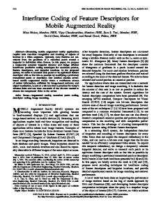
Some examples from the broad spectrum of Game/VR/AR (GVAR) technology applications: from VR/AR training, through VR/AR games, VR/AR storytelling, VR/AR edutainment, to VR/AR cultural heritage preservation, etc. (real-time snapshots from VHD platform and VHD++ component framework based applications)
3
Figure 1.3
Planned and unplanned architectural structure and evolution.
4
Figure 2.1
Main forces acting presently upon interactive real-time 3D audio-visual simulation software systems (GVAR systems, i.e. Games, VR, AR).
8
So common successful application lifecycle scenario: from good analysis and design, through subsequent iterative improvements, extensions and adaptations to always new requirements, until the critical point of architectural saturation.
21
Toolkits in application design and development: emphasized code reuse, lowered application complexity, improved portability, maintenance and replacement potential, in effect application life span is extended
22
Figure 4.3
Framework in context of the application design and development.
26
Figure 4.4
Synergistic relationships among toolkits, patterns and frameworks in context of largescale system architecture modelling.
30
Component reusability vs. component composability in relation to granularity, abstraction levels and application domains.
43
Figure 5.2
Connection-driven vs. data-driven programming style: key features and consequences.
49
Figure 5.3
Relationships between extensibility dimensions, extensibility space and bottleneck interfaces defined by the component model.
54
Horizontal and vertical aspects of analysis in case of GVAR system engineering: abstraction levels vs. functional domains
58
Component framework extensibility dimensions are mostly of singleton character (white frames around FA, FC, FD). In contrast those defined by component model are rarely of singleton character (here only CC).
60
Component development: respective roles of plug-in and bottleneck interfaces in context of the late binding mechanism.
64
Role of composition mechanisms and tools along the key phases of the CBD process: parallel component development, application composition and final application release.
67
Composition: conceptual comparison of structural vs. behavioural coupling of components in context of the target application composition.
68
Vertical vs. horizontal specialization bias of VR/AR engineering solutions taking into account system, simulation and application abstraction tiers (vertical) and focus on the software or the content functional side (horizontal).
78
From toolkits to component frameworks: growing system engineering flexibility and availability of more advanced system composition mechanisms and tools.
79
Figure 1.2
Figure 4.1
Figure 4.2
Figure 5.1
Figure 5.4 Figure 5.5
Figure 5.6 Figure 5.7
Figure 5.8 Figure 6.1
Figure 6.2
- xi -
Figure 6.3
From feature-driven to architecture-driven engineering: relation to object-oriented and component-oriented methodology.
91
Presently dominating two non-systematic game engine reuse strategies: retrofitting and extraction.
94
Generality vs. performance: forces acting on the VR/AR and GameDev system development ends of the spectrum.
96
GVAR system engineering: relation between abstraction tiers, scope of tasks, and required skills.
97
Evolution of scenegraph concept and its role: from object-oriented structural scene representation (a), through introduction of behavioural aspects allowing for easy creation of interaction and simple custom actions (b), until whole application abstraction containing custom non-graphical node extensions encapsulating application/simulation level services (c), finally overloaded to play even more advanced roles in application engineering (d).
99
Aspect-based separation of state database (content side components organized in form of multi-aspect-graph) and application abstraction (software side components defining and using aspects at runtime).
104
Evolution of the GVAR system development methodology: (a) from the direct reliance on the low-level API’s, (b) through wide adoption of scenegraph leading to its use as an application abstraction, (c) to possible component framework based methodology employing multi-aspect-graph approach separating content from software side components, and selective aspect-based data access model from application execution model.
107
Overview of the VHD++ component model elements and their structural and behavioural characteristics: (a) component types and their specialisations, (b) relation to GVAR system vertical abstraction tiers and horizontal functional domains, (c) behavioural and structural overview of vhdServices and vhdProperties.
110
Main states and transitions of vhdService and vhdProperty components’ finite state machines.
112
Figure 8.3
Bottleneck interfaces and collaboration patterns among VHD++ components.
118
Figure 8.4
Relations between main levels of system deployment, configuration, and composition used by the late binding mechanism to initialise and start execution of component collaborations.
120
Overview of the execution model and scheduling policy: relation between component framework, scheduling (updates) of vhdService components, and access to the aspect-graphs through the main aspect-graph represented by the hierarchy of vhdProperty components.
123
Concurrent access policy in context of the execution model: main aspect-graph composed of vhdProperty serving as a concurrent access synchronisation layer featuring entry points allowing vhdServices to access data underneath.
128
Selective resolution of concurrent access demands in case of aspect-graph intersections: demands coming from vhdServices and resulting order of selective synchronisation on vhdProperties.
131
Collaboration policy in context of the execution model: control flow in case of connection-driven collaborations based on provided and required procedural interfaces
135
Figure 6.4 Figure 6.5 Figure 6.6 Figure 7.1
Figure 7.2
Figure 7.3
Figure 8.1
Figure 8.2
Figure 8.5
Figure 8.6
Figure 8.7
Figure 8.8
- xii -
Figure 8.9
Figure 8.10
Figure 8.11 Figure 8.12 Figure 8.13 Figure 8.14 Figure 8.15
Figure 8.16
Figure 8.17
Figure 8.18 Figure 8.19
Figure 8.20
Figure 8.21
Figure 8.22
Figure 8.23
Figure 8.24 Figure 8.25 Figure 8.26
Collaboration policy in context of the execution model: control flow in case of datadriven collaborations based on published and received transient data objects (vhdEvents)
137
Collaboration policy in context of the execution model: control flow in case of datadriven collaboration based on controlled or observed persistent data objects (vhdProperties)
138
Time policy: a typical runtime hierarchy expressing time dependencies between clock instances.
142
Conceptual, top and side view on the vhdRuntimeEngine.
144
Main elements of the vhdRuntimeEngine implementing strongly coupled set of invariant fundamental services supporting and enforcing VHD++ component model.
145
Design foundations: low-level separation of three main class hierarchies: concrete, exceptions, and interfaces.
148
vhdDelegates vs. interfaces: comparison in case of “callback scenario” where a notification originating within scope of VHD++ classes needs to be handled by external classes (independent of VHD++ classes).
152
vhdFields and vhdFieldTransducers: data dependency graph distributed among class instances allow for asynchronous data-driven collaborations between system elements.
155
vhdFields vs. Multi-Aspect-Graph: a data dependency graph specified by vhdFields can be used to define an aspect-graph expressing spatial dependencies between vhdProperties
156
Architectural relationships between main elements of vhdRuntimeEngine.
158
vhdRuntimeEngine initialisation phase: configuration information created by vhdXMLPropertyLoader based on the XML hierarchy is passed to vhdRuntimeSystem for validation, and then forwarded to the vhdRuntimeEngine instance that may start initialisation.
162
vhdServiceManager: architectural relationships between main classes supporting lifecycle management and bottleneck collaborations of vhdServices (architectural “zoom in” of Figure 8.18).
169
Fault tolerance and localisation: role of the vhdServiceHandle in shielding of vhdRuntimeEngine execution from localised runtime faults (interception and forwarding of calls).
171
vhdServiceContext used by vhdServiceManager for management of vhdService bottleneck collaborations using instances of the vhdProvidedServiceInterface, vhdRequiredServiceInterface, vhdPropertyController, vhdPropertyObserver, vhdEventPublisher, and vhdEventReceiver classes.
175
vhdScheduler customisation point: selection between custom scheduling policy or default VHD++ scheduling policy based on scheduling patterns specified in vhdServiceSchedulerConfigProperty.
180
vhdPropertyManager and its customisation point allowing for connection of additional handlers reacting to vhdProperty addition, removal, or change.
183
vhdEvent class hierarchy separating system, simulation and call events (extension of the VHD++ class hierarchy presented in Figure 8.14).
185
vhdEventManager: architectural relationships between main classes supporting realisation of the VHD++ event model (architectural “zoom in” of Figure 8.18)
186
- xiii -
Figure 8.27
Figure 8.28 Figure 8.29 Figure 8.30 Figure 8.31
Figure 8.32
vhdEventManager: customisation points allowing for introduction of custom vhdEvent filters and handlers based on vhdIEventFilter, vhdIEventHandler interface implementation, or through vhdEventFilterDelegate, vhdEventHandlerDelegate delegates.
188
Exporting of vhdService provided procedural interfaces to the procedural scripting layers defined by scripting languages (e.g. Python, Lua, etc.).
190
vhdPythonService: vhdGUIWidget providing Python scripting console allowing for writing, testing, and management of the scripts handled by vhdPythonService
191
vhdGUIManager: management of GUIs forms an optional layer on-top of the VHD++ component framework.
193
Independent extensibility dimensions of the VHD++ Component Model vs. independent extensibility dimensions and customisation points of the VHD++ Component Framework
195
Examples of vhdGUIWidgets supporting component development and application composition.
196
Figure 9.1
Selected application domains of VHD++ component framework.
206
Figure 9.2
vhdJUST System: Immersive VR situation training of health emergency personnel: immersed trainee and execution of ordered Basic Life Support procedures.
207
vhdCAHRISMA System: VR reconstruction and preservation of cultural heritage: virtual human crowd simulation recreating a ceremonial liturgy.
208
Figure 9.4
vhdSTAR System: AR training of hardware maintenance professionals.
209
Figure 9.5
vhdLIFEPLUS System: AR reconstruction of life in ancient Pompeii.
210
Figure 9.6
vhdMAGICWAND System [Abaci04]: VRlab Immersive VR edutainment system featuring intuitive HCI based on gesture and speech recognition.
211
Behavioural animation system made up completely using behavioural coupling capabilities of VHD++ component framework i.e. Python scripting layer providing visibility of all ready-available vhdServices.
211
X3D profiles and their mutual inclusion and intersections.
229
Figure 9.3
Figure 9.7
Figure 11.1
- xiv -
List of Tables Table 4.1
Table 5.1 Table 6.1
Comparison of the key features of applications, patterns, toolkits, and frameworks together with the key synergistic relationships and role they play in the domain of GVAR systems.
31
Comparison the traditional vs. Component Based Development (CBD) process elements.
38
Arbitrary selection of VR/AR engineering approaches classified according to the application domain and their respective character.
76
- xv -
1. Introduction Nowadays we witness a profound sociological transformation being a direct effect of unprecedented advancements in the information and telecommunication technologies. As proclaimed already some time ago by sociologists and futurologists this transformation will spur the creation of a global information society that will rely heavily on the interactive audio-visual communication channels. The technological advancements will change fundamentally the ways people learn, work, communicate, socialize and entertain. Almost certainly it will change the meaning of these words as we know it. In order to see those changes we do not have to wait long. They are happening now, and they are happening very fast. Facing Expectations. What is behind this phenomenon ? The very recent progress in computer graphics technology, yielding powerful yet affordable hardware, put a completely new light on the VR/AR systems, and on their cousins, interactive video games. Interactive content rich games, networked and persistent epic environments, live TV shows featuring synthetic characters, interactive TV services, are becoming nowadays the R&D focus of the media industry. This leads to the emergence of a new attitude and expectations of coming generations to the potential offered by the advanced VR/AR technologies. Observing growing ubiquity of the interactive 3D audio-visual systems we may expect the next to come, “beyond-games” diversification phase that will target education, training, productivity, communication, cultural heritage preservation (reconstruction and documentation), infotainment, edutainment, sportainment, mobile applications, etc. Availability. Immense investments combined with the intensive research in the core fields of real-time graphics made the technologies, once affordable to a few research laboratories and government based institutions, now widely available. They are available on various platforms, ranging from game stations, through personal computers, to specialized VR/AR systems featuring advanced hardware user interfaces. We are reaching the point where majority has nearly equal access to similar software and hardware technologies providing comparable performance at comparable price. Complexity. So there is a natural question that appears immediately: what qualities or concepts will make the distinction and assure the success of particular solutions in the highly competitive R&D environment ? Will it be a high network bandwidth, fast graphical rendering, realistic illumination, photo-realistic models, physics-based animation, natural and sophisticated responsive behaviour of synthetic characters, artificial intelligence, easiness of interaction, immersion quality, VR devices, mobility or maybe some other features targeted nowadays by video games and VR/AR systems. Similarly to the question the answer seems to emerge immediately: all of them.
-1-
It seems that the success of a particular interactive real-time audio-visual products or services will not be a function of any certain quality, nor the number of separate qualities involved. Instead it will be based on the way or rather the art of combining those qualities, relating them and letting them interplay inside one, consistent, and extensible framework. So it will be the complexity and the technologies that will let handle this complexity that will distinguish the successful solutions in the new era of interactive audio-visual ubiquity. Quoting Bill Raduchel, former Chief Strategy Officer of Sun Microsystems: “The challenge over the next 20 years will not be speed or cost of performance; it will be the question of complexity”. Although this was stated in general context of software industry, we can see that since very recently the same observation starts to apply to the booming game industry [Crespo02][Rubin03][Brooks03][Malakoff03], and already since some time to the modern VR/AR system engineering [Capps99]. Pressure and Tradeoffs. Especially on the industrial side it becomes clear that in the extremely competitive environment there is only one rule to follow: deliver always new, always more, in shorter time. Chasing that continuous tough demand results in system complexity rising exponentially with the number of heterogeneous technologies and semantically distant elements being integrated.
high quality
You may have only two out of the three available … Software Development Tradeoffs
in short time
Figure 1.1
at low cost
Key tradeoffs between quality, time of development and cost of development in case of design and implementation of software systems
Object-oriented toolkits, knowledge of well established architectural and development patters plus human skills and experience still help to do the job but in order to stay on the cutting edge of tomorrow’s development speed, massive reusability of components, easiness of replacements, extensions, adaptations, reconfigurations and maintenance must be addressed. This explains the current rapidly growing interest of both research and industry in advanced, complexity curbing, component-based framework methodologies that while already intensively explored in other IT domains are just coming to life in the
-2-
VR/AR domain. The main objective of all those methods is to minimize the key tradeoffs involving quality, time and price of development (Figure 1.1) through broad reuse of system architecture (frameworks) and code (components). VR preservation of cultural heritage
VR training of medical personnel
VR social event
AR training of machine operation
VR edutainment game
AR edutainment for archeological sites VR theatre storytelling
AR entertainment chess game
Figure 1.2
AR television production
Some examples from the broad spectrum of Game/VR/AR (GVAR) technology applications: from VR/AR training, through VR/AR games, VR/AR storytelling, VR/AR edutainment, to VR/AR cultural heritage preservation, etc. (real-time snapshots from VHD platform and VHD++ component framework based applications)
VR/AR Melting Pot. VR/AR systems rely heavily on the interplay of heterogeneous functional elements. Because of that inherently interdisciplinary character VR/AR domain can be viewed as a melting pot of various technologies which although complementary are non-trivial to put together. Many of those technologies gain a lot of individual R&D interest but still it is not generally understood and there are barely any accepted guidelines and approaches in the matter of integration of those functional artefacts under the roof of one consistent framework. In other words we have nowadays many masterpieces of atomic technologies but still we miss a well understood and generally accepted strategy for putting them up so they would constitute the whole bigger than the simple sum of its parts. The missing element is a glue framework that would curb the complexity and make the resulting system machinery a consistent and seamless unity leaving at the same time open handles and hooks for replacements and extensions. Patterns of Structure and Evolution. The quest for the unifying framework and the reusable patterns can be compared to the construction engineering and architecture efforts [Alexander77] looking continuously for the answer to the question: what makes the ideal city ? Cities are being built since ancient times. Now we know that even the masterpieces
-3-
of the modern urban architecture cannot exist at random, separated form the global infrastructure providing all accessories and facilities like roads, electricity, telecommunication, transport, water supply, sewage system, heating, ventilation, security, etc. Only when properly integrated, all those elements, although each of them replaceable, constitute the whole bigger than the simple sum of its parts, which is the living and functional organism, called the city. The same seems to be so true in case of the software components that need a unifying framework that would provide all the necessary infrastructure and semantics to integrate existing components and facilitate adaptation of those to come.
Figure 1.3
Planned and unplanned architectural structure and evolution.
Using again comparison to the urban architecture domain, the cities, similarly to the software systems, change continuously. There are no two identical cities. Each of them has both successful and poor solutions. Each of them evolves with the technological and social changes in order to meet quickly changing needs of inhabitants. Some of them are completely abandoned while other flourish. But what makes those existing ones similar are repeatable patterns used in their implementation. The same applies to the software systems. The development history of a system does not finish with the final release. Systems are being maintained, optimised, particular modules or components replaced, extensions added. Those inevitable changes must not ruin the whole system architectural framework each time they are executed.
-4-
1.1 GVAR Domain For the purpose of the following discussion we introduce GVAR term to denote a specific domain, being a cross-section of Game (G), Virtual Reality (VR), Augmented Reality (AR) systems possessing the following characteristic features: 9 9 9 9
3D audio-visual simulation: 3D graphics and sound real-time performance: ideally 25 frames per second interactivity: user in the loop 3D character simulation: stand alone or in context of virtual storytelling
In this particular context character simulation has a broader meaning. Although intuitively connected with all types of simulation entities revealing anthropomorphic features (e.g. virtual humans, puppets, etc.) it encompass as well the broadly understood elements of the synthetic 3D simulation environment (e.g. landscape elements, architectural artefacts, flora elements, furniture, clothes, etc.). The purpose of this explicit characterisation is to draw a clear division line between GVAR and other types of systems. For example Computer Aided Design (CAD) systems, focusing on engineering, may as well feature elements of real-time interactive simulation, however they do not address issues related to efficient real-time character simulation in context of interactive virtual storytelling.
1.2 Inspiring Analogies: New Need, New Context, New Challenge When 550 years ago Gutenberg was printing the famous 180 copies of the 42-line Mainz Bible (1452-1453/1454) he did not know that his invention would give a birth to a new mass media form. His ingenious idea consisted of the use of a generic printing frame and movable types. Until that moment each book was a unique piece of art requiring painful and expensive manual labour performed by a skilful craftsman who was taking care of all aspects of the work involved. The Gutenberg’s invention changed it forever paving the way to the broad reach of a new mass medium and its great diversification over time to finally cover the immense spectrum of domains we can enjoy nowadays. Gutenberg answered the strong need of his time for a more affordable mean of knowledge communication and sharing. His invention had a profound impact on culture. More than 100 years ago, in 1903, Henry Ford opened his company and soon after that, in 1908 the innovative component standardization and assembly line based production process gave a birth to the famous Ford T, reshaping forever the industrial manufacturing process. Before that cars were manufactured out of custom and non-optimised parts. Thanks to the standardization the production of components could be outsourced and providers selected on the competitive basis. In turn it allowed for better planning, cost optimisation, quality assessment, risk estimation and management, etc. Ford answered the
-5-
need of the industrial society of his time for an affordable mean of transport. His methodology transformed the industry, stimulated growth of other economy sectors and created new work places. Nowadays the knowledge oriented society face the appearance of a new form of a storytelling mass medium. Today games and soon VR and AR systems will become ubiquitous as the coming generations have completely new expectations concerning communication, education, leisure and social activities. There is a new rapidly emerging need to be addressed Unlike other media types GVAR (Game/VR/AR) storytelling systems are both cultural (Gutenbergian) and industrial (Fordian) entities combining advanced interplay of art and engineering. The revolutionary advancements in the real-time 3D graphics technology combined with the extremely competitive environment requiring to deliver always newer, always faster, always more, in the shorter time resulted in the complexities that can be barely handled with the technologies and methodologies currently at hand. Using the Gutenbergian analogy, similarly to the medieval books, currently GVAR’s are manufactured painstakingly in the manual fashion by groups of highly skilful and multidisciplinary craftsmen knowing how to forge art and technology into a unique solution. In effect GVAR’s tend to be highly monolithic and closed, far from reusable and extensible. The required know-how and multidisciplinary steep learning curve make it virtually impossible for wider numbers of creators to enter. Finally the price and risk involved constrain the diversity and penetration and exploration of new application domains. Using Fordian analogy, the lack of standardization of components used for construction of today’s GVAR’s makes optimisation virtually impossible. In many cases developers and/or designers provide “too good” (i.e. over-performing, too expensive) or “too bad” (i.e. under-performing) elements, but once put together it is usually too late for modification that would require propagation of changes to the whole system and/or production pipeline. In effect in most cases we face “intuition & luck driven” process. This makes process control and risk estimation hard for the high level managers, publisher and investors who require concrete measures and norms in order to perform their assessments. Lack of standardization constrains outsourcing, limiting number of component providers that would like to try their chances on the market. The transition is happening now. Scale and complexity need to be addressed in a novel way. Software and content mass production stressing 18 or even 6 months production cycles, involving teams of 30-70 people maintaining on average 0.8M-1.2M lines of code and ~200GB large content assets, even if supported by multimillion budgets cannot rely on the current methodologies. Using the Gutenbergian analogy there is a need for a
-6-
common reusable runtime engine/framework (broad architectural reuse) and movable components (mass code reuse) encapsulating heterogeneous simulation technologies. Recalling Fordian analogy we need stronger standardization of both content and software components that in turn should allow for definition of unified GVAR production process covering the whole value chain of technologies and methodologies.
-7-
2. Motivation The main motivation of this work is based on the strong premise that all mature engineering domains sooner or later recur to the component-based approaches. It is based on the recognition that all complex engineering entities are being built by groups of experts chasing the continuously evolving state of the art. Next we present some particular aspects of the motivation behind this work.
2.1 Forces Shaping the Future Following Grady Booch’s observation [Booch00] the future of software will be driven by the two main concerns: migration to the higher abstraction layers, and team productivity vs. individual productivity. In particular Booch emphasizes the following individual factors that are to shape the next to come software engineering methodology: 9 9 9 9
component based systems will dominate more non-programmers will end up programming continuously evolving systems will become the norm for organizations technology will continue to change rapidly
Given the forces acting currently upon the GVAR system engineering (Figure 2.1) it seems that the above observation starts to apply very quickly to the GVAR domain of today. SYSTEM VIEW: • scale and complexity • heterogeneous simulation technologies • feature rich simulation • performance and reliability • compatibility and interoperability
PROCESS VIEW:
• evolution and legacy systems
• large teams
• huge content databases • novel interaction paradigms
• heterogeneous expertise
GVAR Systems
• massive design and code reuse • rapid prototyping with heterogeneous components • experimentation in context of other technologies • short development cycles • outsourcing • “mass production” of games
HARDWARE VIEW:
• integrated software and content management
• continuous 3D technology churn • multiple platforms • diversity and need of novel in/out devices
Figure 2.1
Main forces acting presently upon interactive real-time 3D audio-visual simulation software systems (GVAR systems, i.e. Games, VR, AR).
-8-
Component-orientation is already actively explored on the VR/AR research side. On the GameDev industrial side it is expected to be the next evolutionary step replacing the monolithic Game Engine based development as we know it today. Concerning more non-programmers ending-up programming statement already now there is a substantial community of developers, artists and researchers using VR/AR technologies through the high level visual authoring tools and scripting layers hiding all programming level complexities and limiting the otherwise steep learning curve. The best examples are the virtual character behavioural simulation and the AI domain. On the GameDev side we witness rapid growth of so called 4th party development community i.e. MOD (modification) community using high level authoring and scripting approaches to add both content and functional modifications to the existing products, sometimes reshaping completely the original versions. MOD communities rely in majority on teenage people who thanks to the high level interfaces can cope with the advanced technology without any formal computer science background. So we see clear transition from core system programmers to system composers who focus on selection and wiring of components on the high abstraction level. While in case of enterprise information management systems evolution and legacy code integration is the norm, it already appears in case of VR/AR and GameDev. In context of GVAR it is widely recognized that green-field programming era is over and most organizations need to handle evolution of their legacy systems, which without systematic approaches to architecture and composition will be unfeasible. In case of VR/AR side widely used object-oriented application frameworks and scenegraphs are concerned. On the GameDev side it applies to Game Engine reuse and retrofitting. The last observation on the continuously and rapidly changing technology seems to be reflecting exactly the current situation on the GVAR system engineering side. Due to the extreme competition new 3D graphics hardware is being released now in cycles shorter than 6 months. Organizations developing products for multiple game platforms (PC, PS2, XBOX, GameCube, NGage, etc.) need to be separated from the hardware specifics by proper component-oriented middleware solutions. Middleware should allowing for smooth migration to the next generations of hardware that is obligatory every 4-5 years given the typical console lifecycle. Migration should include replacements of obsolete components and additions of the new ones that exploit new hardware features.
2.2 Adapting CBD to GVAR System Engineering On the side of enterprise information management system engineering, since late 90’s we observe the rapid emergence and adoption of Component Based Development (CBD)
-9-
methodologies that led to appearance of the three main component platforms: Sun’s Enterprise JavaBeans (EJB), Microsoft’s COM+ and CLR (part of .NET), Object Management Group (OMG) CORBA v3 Component Model (CCM). At the same time on the maturing GVAR system engineering side, currently predominant toolkit, and Game Engine based engineering approaches reach their limits. Encouraged by the success of CBD on the enterprise application side, GVAR system development community is turning towards exploration of CBD applicability to the engineering of interactive real-time 3D audio-visual applications. The present ensemble of broad initiatives and particular efforts focus on various abstraction tiers of GVAR systems (system, simulation, application). It targets elaboration of implementation agnostic component models, and their practical realizations - component frameworks. We can already see some of the first results of those efforts that are listed briefly next in order to illustrate their diversity. Concerning the VR/AR side of the GVAR domain, a prominent example of a broad standardization initiative focusing on simulation abstraction level and aiming at elaboration of implementation agnostic component model is Extensible 3D Modelling Language (X3D). In context of Web3D applications an example of high-level declarative component model formalism based on flexible and extensible Component Interface Model is JAMAL [Rudolph99]. Similar, declarative approach to Web3D application composition is proposed by CONTRIGA [Dachselt02]. Both of them focus on implementation independent declarative component models using high-level interface description languages. Examples of concrete component framework realizations for Web3D application development are Three-Dimensional Beans [Dorner00][Dorner01] and SAVE [Haller01]. Both of them are based on existing JavaBeans component platform and Java3D functionality. On the AR side we can find DWARF [Bauer01] and AMIRE [Dorner02][Haller02] component frameworks. An example of a component framework for both VR and AR applications is I4D [Geiger02]. On the VR side, the first approaches to modularisation and componentisation go back to TBAG [Elliot94], and more recent MAVERIK [Hubbold01]. The following attempts to dynamic VR system composition are reported by VRJuggler [Bierbaum01], DIVERSE [Kelson02]. In context of distributed VR systems the examples of component-based frameworks are BAMBOO [Watsen98][Watsen03], NPSNET-V [Capps00][Kapolka02], JADE [Oliveira00], and MOVE-ANTS [Garcia02]. Concerning the industrial GameDev side of GVAR domain the systematic component-based approaches are yet to come, which constitutes a clear exploration opportunity. However already we can hear the first voices recognizing the urgent need of a new approach allowing for composability end exchange of functional modules of the Game Engines [Fristorm04], [Malakoff03]. We can find as well the first bookshelf positions discussing specifically object-oriented and component-oriented game
- 10 -
development process [Gold04]. Here some examples of component-based approaches include the micro-components of [Shark3D04], data-driven component system SKRIT [Bilas02], and behavioural composition using high-level visual programming tools of [VirTools04]. Urgent need of component orientation is as well recognized by the real-time 3D visualization industry focusing on consumer oriented product presentation [Groten03]. It is worth to mention that similarly to GVAR, other domains as well explore applicability of CBD to domain specific problems related to integration, interoperability and massive reuse. A good example is a Common Component Architecture (CCA) initiative in domain of high-performance scientific computing [Armstrong99]. Other interesting examples of the component frameworks are pLAB component framework for real-time physically-based modelling and simulation [Learhoven03], MacVis [Hagen00] component framework combining agent and component methodology for optimisation of scientific visualisation, and VISSION component framework for scientific simulation and visualisation [Tela99]. Summarizing, it is important to note that investigation, elaboration, validation and possible adoption of promising CBD methodologies is a gradual and relatively slow process. Development of the domain specific component models and frameworks, even if based on the existing component platforms like EJB, COM+/CLR or CCM, is a long iterative process requiring validation in multiple projects and by many people with all consequences of evolution and change management. Frequently the “build twice” rule applies that requires the first solution to be dropped completely in order to allow for design and development of a new version, based on the lessons learnt. Finally adoption of CBD methodology incurs substantial transition time. From the organization perspective transition to CBD presents a strategic decision that once taken reshapes profoundly both structure and process of development, hence it is rarely of ad-hoc nature.
2.3 Advanced Virtual Character Simulation Following the GVAR domain definition provided in the previous chapter, apart from the 3D simulation, real-time performance and interactivity we require that the component oriented approach supports integration and interoperability of components encapsulating advanced virtual character simulation technologies like keyframe, procedural and realtime motion capture animation, skeleton animation blending, skin deformation, face animation, speech, physically based cloth simulation, path planning, interaction of virtual humans with the scene elements, behavioural simulation, real-time crowd simulation, etc. This is based on the recognition of the increasing complexity and importance of the advanced virtual character simulation in multiple GVAR application contexts like training,
- 11 -
education, rehabilitation, virtual cultural heritage preservation, virtual storytelling, intuitive Human Computer Interfaces (HCI), interactive TV, entertainment, etc. An appropriate component based solution should uniformly address needs of researchers and developers on both sides of the R&D spectrum. Researches should be able to work within their respective domains using the component framework as a common environment allowing for experimentation and easy validation of the proprietary solutions in context of other complementary simulation technologies. In this way successful solutions could be incubated yielding the components directly reusable by developers who should focus on reuse, composition, and optimisation instead of designing and developing the target applications from the scratch. Hence, one of the main aspects of motivation behind this work is related to the current lack of any widely referenced component model, and implementing it component framework, that would target GVAR domain with a specific focus on the advanced virtual character simulation technologies. This part of the motivation is based on the belief that virtual characters being the most complex simulation entities of the nowadays GVAR systems need a proper component-oriented approach addressing all abstraction tiers – system, simulation and application. In particular, an important part of motivation comes from the practical experience and lessons learnt from the several years of exploitation of the Virtual Human Director (VHD) platform [Sannnier99]. VHD was a successful integration attempt of multiple advanced virtual human simulation technologies (keyframes, walking engine, real-time motion capture, animation blending, skin deformation, face animation, text to speech synthesis, object grasping, etc.) in form of a modular, functionally flexible, but unfortunately still highly monolithic system. Based on SGI Performer, it featured a mixture of C and C++ modules running on SGI IRIX operating system. It was successfully used in multiple projects, by many researchers and artists, for both real-time interactive VR/AR simulation, and real-time interactive authoring of the VR/AR storytelling productions [Kshirsagar99], [Lee99], [Nam99], [Torre00], [Balcisoy00a], [Balcisoy00b], [Balcisoy01]. With time it was equipped with a set of GUIs allowing for remote (over TCP/IP), interactive control of virtual humans and authoring of linear scenarios. However continuous system exploitation requiring frequent adaptations, replacements, and extensions done in parallel by multiple developers lead finally to the saturation of the original architectural capacity. In effect multiple versions of the system had to be maintained. Strong static (compile level) dependencies between the modules and lack of explicit boundaries lead with time to appearance of mutually exclusive functional elements that were not movable between different versions of the original system. In many cases disabling (unplugging) of undesired functionalities was not feasible due to the big architectural footprint related to the global and uncontrolled dependencies. As a result, based on the lessons learnt, we were forced to look for a new approach that would allow us to handle the complexity. In
- 12 -
effect we started to explore feasibility of a component-oriented approach that would allow for cross-project reuse of an application agnostic architecture (architectural cross-section), independent extensibility and dynamic composition of target applications out of components encapsulating heterogeneous simulation technologies.
- 13 -
3. Scope and Structure of Work
3.1 Scope of Work Following the current state of the art of the Component Based Development (CBD) methodology and the emerging needs of GVAR system engineering domain the key goals of the work are formulated as follows: 9 elaboration of a domain specific Component Model 9 its practical realization in form of a Component Framework 9 validation of the proposed approach across the set of VR and AR systems featuring advanced virtual character simulation technologies used in context of virtual storytelling applications Component Model. Elaboration of an appropriate component model is based on the non-trivial systematic mapping and adaptation of the CBD methodology as understood today, taking into account specific requirements of the GVAR system engineering. We perform step-by-step selection and analysis of the key concepts, issues and consequences of the in today CBD methodology important from the GVAR system engineering perspective. We investigate how they manifest themselves, and what adaptations and extensions of those concepts are required. In course of the analysis we consider both development process and architecture (structural and functional aspects). From the development process point of view we stress parallel development and take into account requirements of the three main actors of the process: component framework developers, component developers and component system developers (application composers). From the architectural perspective we identify and address explicitly three main vertical abstraction tiers of modern GVAR systems (system, simulation, and application) and semi-continuous horizontal spectrum of functional domains stretched between software (computing) and content (storing) extremities. Taking into account the horizontal spectrum we investigate appropriate structural and behavioural dynamic coupling requirements for the components from the storing and computing side of the spectrum. In effect we propose a domain specific component model. We introduce domain specific definition of a component, and an extension of the component interface concept enabling uniform handling of both connection-driven (synchronous) and data-driven (asynchronous) composition models and programming styles. Finally we specify independent extensibility space of the proposed model through identification of the key independent extensibility dimensions. In context of the component model we explore features and consequences of the multi-aspect-graph concept.
- 14 -
Component Framework. We provide concrete realization of the component model in form of a C++ based component framework (VHD++). In this context we investigate and identify all necessary fundamental coordination mechanisms to support and enforce the proposed component model, taking into account respective quality attributes characteristic for the target domain (e.g. performance, responsiveness, concurrency, fault tolerance, scalability). For this purpose, we turn towards an application independent micro-kernel design pattern requiring the framework kernel to be self-contained and completely independent of any 3rd party solutions. In particular, it means independency of any direct mode 3D graphics rendering or scenegraph solution. As such, the kernel can be compared to the specialized operating system. Similarly to an operating system it needs to provide all necessary fundamental mechanisms enabling resource management, concurrency, reflection, late binding, various styles of inter-component collaboration (specifically connection-driven and data-driven), and lifecycle management of components (loading, instantiation, initialisation, power supply, pause, resume, termination, etc.). The kernel is required to have an active character featuring inversion of control in respect to the components. Proposed component framework is to addresses the needs of application composers and component developers. In context of application composition we distinguish and provide support for two key types of coupling: structural and behavioural. Structural coupling is based on declarative scripting. We propose an XML-based, hierarchical, and independently extensible semantics. It allows for uniform expression of the system composition out of the software (computing) and content (storing) components, including configuration of their mutual dependencies and collaboration patterns. Behavioural coupling is based on procedural scripting. Python, object-oriented, interpreted programming language is used for this purpose. Both types of coupling must have dynamic character i.e. they are to be resolved at system run-time (as opposed to the static coupling approach resolved at compile-time), which assures fully dynamic system composition capabilities. Dynamic system composition is based on the custom implementation of the late binding and component reflection mechanism. Proposed mechanisms support the extended definition of the component interface assuring uniform handling of connection-driven and data-driven composition (wiring) styles. Apart from application composition the XML declarative semantics allows for dynamic configuration of the kernel operational parameters including search paths, scheduling templates, system, simulation and warp clocks, etc.) It allows as well for dynamic configuration of component operational parameters through generic argument sets. Component framework provides strong support for concurrency. It offers dynamically configurable scheduling mechanism allowing for expression of update and
- 15 -
synchronization patterns of active components in form of reusable templates. It is especially important in context of advanced virtual character simulation components, which in order to yield an optimal performance need to conform to certain scheduling patterns involving mixture of synchronized sequential and concurrent updates. In context of both component development and application composition the frameworks provides plug-able diagnostic tools offering graphical user interfaces and allowing for runtime inspection and control of diagnostic messages, composition, lifecycle, clocks, etc. Given the component model and component framework implementation we propose possible GVAR system componentisation strategies taking into account the main abstraction tiers, separation of functional concerns (computing vs. storing), granularity, potential of reusability, targeted quality attributes, collaboration patterns, etc. In effect we propose a concrete set of components (e.g. rendering, sound, skeleton animation, skin deformation, face animation, speech, cloth simulation, crowd simulation) in order to investigate how the framework supports handling of their mutual dependencies and collaborations, especially in context of low-level change management (e.g. introduction of new skeleton topology for virtual character components, introduction of new scenegraph database for scene components). Validation. Here on the validation of the proposed CBD methodology from the perspective of the main three actors of the CBD process (component framework developer, component developer, application composer). In particular, we study examples of concrete components, inter-component collaborations, and instances of VR/AR storytelling systems featuring various combinations of advanced virtual character simulation technologies, immersion, and interaction paradigms
3.2 Limitations In the scope of work we do not explore specifically the class of issues related to the Component Based Development of multi-user GVAR systems targeting Shared Virtual Environment (SVE) simulation. However given the proposed systematic approach to componentisation together with all generic mechanisms supporting various composition and inter-component collaboration styles (specifically data-driven collaboration) this can be seen as the future work.
- 16 -
3.3 Structure of Discussion In Chapter 4 we introduce the main concepts and terms related to the design and development of modern, large-scale, complex software systems. In particular we discuss the role of systematic approach to architecture, and contrast it with the main problems caused by ad-hoc development and evolution of monolithic applications. We show the role and consequences related to the use of widely popular nowadays toolkits, design patterns, and object-oriented application frameworks (OOAF). We outline synergies and differences between applications, patterns, toolkits and frameworks especially from the point of optimization, design and code reuse. Finally we emphasize the main differences between widely popular nowadays object-oriented programming and the coming wave of component-oriented programming. In Chapter 5 we perform systematic, step-by-step, systematic analysis, mapping and adaptation of the current understanding of the CBD methodology to the needs of the GVAR system engineering. The resulting GVAR specific CBD methodological template is then validated by confrontation with the set of existing GVAR system engineering solutions in Chapter 6. Mapping to the uniform CBD semantics yields detailed taxonomy and demonstrates the evolutionary convergence of initially isolated architectural (design related), functional (system operation and mechanism related), and development (process related) patterns towards the common CBD methodological denominator. In Chapter 7 we perform critical analysis of the scenegraph concept Following identification of the main problems caused by the overloaded use of a scenegraph as an application abstraction we propose a multi-aspect-graph approach that in context of Component Based Development (CBD), and the strong requirement of independent extensibility, defines an architectural arrangement and runtime binding between content and software side components, optimised for real-time concurrent performance, required by GVAR systems Based on the GVAR specific CBD methodology from Chapter 5 and the multi-aspectgraph concept proposed in Chapter 7, in Chapter 8 we present a GVAR domain specific component model and its practical realization in form of C++ based component framework (VHD++). In Chapter 9 we focus on the validation of the proposed CBD methodology from the perspective of the main three actors of the CBD process (component framework developer, component developer, application composer). In particular, we study examples of concrete components, inter-component collaborations, and instances of VR/AR storytelling systems featuring various combinations of advanced virtual character simulation technologies, immersion, and interaction paradigms.
- 17 -
4. Concepts and Terms In this chapter we introduce the main conceptual idioms and terms related to the design and development of modern, large-scale, complex software systems. The fundamental vocabulary introduced here will serve as a basis for the following discussion where we will perform systematic adaptation of the Component Based Development methodology, as understood today, to the GVAR system engineering domain (Chapter 5). Following the discussion of the respective roles, features, and consequences of the fundamental concepts introduced, in this chapter we present their comparison and discuss existing synergies.
4.1 Architecture Until quite recently the know-how required for design and development of large scale, complex software systems existed in heads of experts who used their long time experience and resulting intuition. The know-how existed informally, in what some authors name anecdote or folklore. Continuously growing complexity of the nowadays software systems elevated the need and importance of systematic approaches to software architecture. Software architecture was proposed as a discipline by [Perry92] which soon gave birth to the profession of a software architect. In effect the late 90’s brought the formal Unified Modelling Language (UML) [Booch99] standard. By that time it has been widely recognized that big systems, developed by teams and not individuals require proven modelling techniques, precise measurements, well-defined development process, they are more and more based on off-the-shelf and pre-built parts, and need to rely on widely adopted standards. As usually in case of terms having broad meaning in various context it is impossible to provide a single definition of software architecture. One of the most generic definitions can be found in “The Unified Modeling Language User Guide” of Booch, Rumbaugh and Jacobson in [Booch99]: “An architecture is the set of significant decisions about the organization of a software system, the selection of structural elements and their interfaces by which the system is composed, together with their behavior as specified in the collaborations among those elements, the composition of these structural and behavioral elements into progressively larger subsystems, and the architectural style that guides this organization.”
- 18 -
In context of component oriented software systems that we are going to discuss further it is worth to recall definition from the widely referenced “Component Software: Beyond Object Oriented Programming” book of Szyperski, Gruntz and Murer [Szyperski02a]: “Overall design of a system. An architecture integrates separate but interfering issues of the system, such as provision of independent evolution and openness combined with overall reliability and performance requirements. An architecture define guidelines that, together, help to achieve the overall targets without having to invent ad hoc compromises during system composition. An architecture provides guidelines for safe system evolution. However, an architecture itself must be carefully evolved to avoid deteriorations as the system itself evolves and the requirements change. The right architectures and properly managed architecture evolution are probably the most important and challenging aspects of the component software engineering” When looking at the above definitions one can immediately notice that while the first, generic definition articulates: 9 structure, 9 behaviour, 9 collaborations and composition guidelines, the second one, in the context of component based systems, stresses: 9 independent evolution, 9 openness. Research on architectural abstraction level is based on the strong premise stating that in case of large and complex systems structure and interaction dominate over choice of particular algorithms and data structures. In the first place systematic approaches to architecture allow for clear separation of the key concerns preconditioning any successful system design: 9 abstract design vs. concrete implementation, 9 computation vs. communication, 9 algorithms vs. data representation
- 19 -
Architectural modeling semantics is developed around the following architectural elements: 9 components: modelling elements representing computation or state 9 connectors: modelling elements representing dependencies and interactions among components 9 configurations: graphs of components and connectors expressing and defining particular architectural instance Until recently the ad-hoc approaches to architecture relied on broad experience and strong intuition of seasoned developers. Many authors describe those ad-hoc approaches as certain type of anecdote or folklore that was existing and passing from generation to generation more as a black-art than codified set of rules and guidelines. Nowadays systematic approaches to architecture rely on widely accepted and standardized notations like UML and employ catalogued domain specific design patterns and semantically rich vocabularies.
4.2 Applications Application targets specific domain and specific use cases thus due to this nature it can be highly optimised. During the analysis phase high priorities are assigned to internal reusability, maintainability and expandability that can be usually achieved by careful design and use of domain specific design patterns. Within the application frame the development team designs and implements only what is needed without necessary focusing on potential extensions and future use cases. In many cases the development team working under pressure and being not concerned with the possible future evolution of the system employs easy to learn and easy to use toolkits and middleware based methodologies that do not define architectural frame and do not support extensions. In effect in most cases any broader code and design reuse is extremely limited.
- 20 -
classes and their mutual relationships analysis & design mu iteration 1 iteration 2
iteration 3
let’s start again boom !!!
iteration N
Figure 4.1
iteration N+1
So common successful application lifecycle scenario: from good analysis and design, through subsequent iterative improvements, extensions and adaptations to always new requirements, until the critical point of architectural saturation.
No matter how well designed initially an application architecture deteriorates with subsequent iterative extensions, adaptations or integrations with other systems. The quality of the initial design measures then the number of major iterations that the architecture can still support. At the certain moment the critical mass of the mutual dependencies between application elements is reached and control over the architecture is lost. In such cases it is usually still possible to maintain the application, remove bugs, make releases but any new substantial iterations would lead to explosion of complexity and complete blurring of the initial architectural design making any further developments virtually unfeasible. In some cases it may even occur that some of the extensions are mutually exclusive as they use incompatible technologies or modules. Sometimes a solution can be found in forking of the development paths but still it only delays an inevitable end. Moreover due to the lack of the common architectural and semantical frame supporting code or design reuse any movements of functionally useful features becomes impossible between forked versions of the initial system. If such moment is reached it is usually easier to gather all experiences and start from the very beginning. This kind of real world, and too common scenario is presented schematically in Figure 4.1.
4.3 Toolkits Object Oriented (OO) toolkits are usually deployed in a form of class libraries containing suites of predefined, related and reusable classes delivering concrete, useful functionalities and solutions to the problems common in particular domains. In general
- 21 -
they vary in domains they are specialized and optimized for. More importantly they may differ substantially in the abstraction levels they operate on and provide users with. So it may happen that two toolkits specialized in one domain offer completely different level of semantics or in other words completely different conceptual vocabulary that the application may express its algorithms in.
application abstraction level
longer life
analysis & design
lower application complexity
9 simplified 9 focus on app level 9 toolkit semantics used toolkit domain abstraction levels
well specified toolkit API improves potential of replacements select useful toolkits
special case of a complete middleware solution separating an app entirely from the OS services
selected toolkits used by the application (bindings do not change)
spectrum of domains covered by toolkits (eg. multiprocessing, networking, GUI, 3D graphics, sound, etc.)
Figure 4.2
Toolkits in application design and development: emphasized code reuse, lowered application complexity, improved portability, maintenance and replacement potential, in effect application life span is extended
Toolkits are used heavily in order to cut application development time and improve its portability. Time is cut both during design and implementation. In the first case designers can operate on the higher abstraction level and thus focus their efforts on the application specifics. In the former case developers use existing and tested code instead of recoding it. Toolkits in general do not impose any architectural requirements on applications using them and as such they emphasize only code reuse and do not address a hard issue of architectural reuse. In some cases toolkits may span over several domains separating applications completely from the underlying operating system thus forming complete and consistent middleware solutions adding to the application cross platform portability. There are as well other important features of toolkits worth mentioning. Designers and developers may use them in a selective way picking only what they need in course of application development (no “all or nothing rule” inherent to frameworks). Being highly optimized for particular domains they usually offer highly performing solutions to domain problems. When carefully selected and used in a particular application frame they rarely cause clashes, as the domains they cover are usually orthogonal. Their popularity is high as they are much easier to learn and master in comparison to frameworks.
- 22 -
Design of toolkits is much harder than those of applications since a toolkit has to provide flexible and effective solution to many applications and for many use cases that are hard to predict at the toolkit design phase. In order to assure generality the toolkit designer must avoid any constraining assumptions and dependencies. Each toolkit need to define its own semantics exposed to the users in form of consistent set of interfaces (API). Figure 4.2 presents schematically the key concepts related to toolkits and their respective role in the application design and development process. It is important to note that although providing many useful functionalities toolkits do not solve the hard problem of application reuse, scalability, extensions, adaptations and reconfigurations. Thanks to toolkits application design can be elevated to the higher abstraction level improving clarity, portability, maintenance and potential for replacements of functional modules separated from the application with well specified interfaces.
4.4 Middleware Middleware is a general term referring to the software layer that separates an application from the fundamental operating system level services. Use of platform independent middleware API assures resulting application portability across multiple operating system environments. A good example illustrating extreme importance and need of complete middleware solution is the game industry that strives for provision of its products and services on multiple hardware platforms existing nowadays. Middleware characteristics may be revealed by both toolkits and frameworks, and in particular to component frameworks. Equally, a set of toolkits or a specific domain framework may separate an application completely from the underlying platform specifics. The main difference consists of how toolkits and frameworks are used respectively, what are the consequences of their use, and which of the approaches is available, necessary or affordable.
4.5 Patterns Patterns codify reusable design expertise providing practically proven solutions to the commonly recurring software development problems specific to particular contexts and domains. Patterns promote design reuse though explicit articulation of both static and dynamic aspects of the design. They can be viewed as micro-architectures specifying abstract interactions between entities collaborating to solve a particular domain problem. They are specified in the language independent manner and do not have any immediate
- 23 -
implementation. In contrasts these are rather examples of patterns that can be found in the implementations. The origin and inspiration for the research on reusable patterns in context of the software engineering domain goes back to the Christopher Alexander’s “A Pattern Language” book [Alexander77] that discusses role of the patterns in the urban architecture. Until mid 90’s patterns existed largely in the programming folklore. One of the first comprehensive and systematic catalogs of design patterns [Gof95] proposed classification of design patterns according to the following four elements: 9 pattern name 9 the problem that the pattern solves: o conditions of applicability 9 the solution to the problem brought by the pattern: o elements involved, their roles, responsibilities, relationships, and collaborations 9 the consequences of applying the pattern: o time and space tradeoffs, o language and implementation issues, o impacts on flexibility, extensibility, portability Since the mid 90’s growing interest and continuous research resulted in further identification of patterns on various levels of abstraction classified by [Souza98] into the following groups: 9 architectural patterns: capturing broad scope and strategic decisions having impact on the overall system structure and performance 9 mechanistic patterns: capturing abstractions of smaller collaborations 9 behavioural patterns: sometimes called detailed design patterns that reside in a single class design scope Patterns can be classified according to the specific domains that they cover like architectural patterns [Buschmann96], patterns for real-time systems [Douglas99][Douglass03], concurrency and networking [Schmidt01], etc. Design patterns play a crucial role in design and development of large-scale software systems. In the first place they allow designers to limit the number of design decisions and in the same way to avoid certain number of common mistakes through reuse of already tested design solutions. In this sense patterns free the designers from choice that in many cases can be overwhelming especially for the novice designers facing multitude of possible design options. They simplify design and increase its clarity. Because of that patterns are particularly indispensable in design and development of complex software frameworks as they help in documentation and communication of the main structural and behavioral concepts to the framework users.
- 24 -
4.6 Frameworks Following a very compact and intuitive definition given by [Rogers97] a framework can be seen as a “partially completed application, pieces of which are customized by the user to complete application”. A framework defines a semi-complete, reusable application architecture based on the domain specific patterns and involving a well-specified set of cooperating concrete and abstract classes. It provides as well a predefined, strongly optimized, set of collaborating fundamental mechanisms common to the given domain. It must define clear customization, replacements, and extension points. Framework based development methodology focuses on massive design and code reuse and relies on the multiple (from tens to hundreds) domain specific design patterns coming from all abstraction levels (architectural, mechanistic and behavioural). In this context design patterns play an important additional role improving design robustness, clarity and documentation. From the system modeller perspective a framework constitute a consistent, concrete environment where: the work can be separated and distributed around well-known extension points of common architectural backbone. Frameworks destined for adaptations and extensions usually come with default implementations that reduces implementation burden promoting lightweight usage. The users simply have to identify and replace elements that do not fit for the particular application. Frameworks tend to curb complexity by limiting number of idioms to learn in order to understand the resulting system structure and behaviour. Frameworks impose overall system architecture that limits the design freedom that is actually highly advantageous in case of large-scale systems. It frees the designers from choice and allows them to avoid sub-optimal decisions that while not initially evident may become problematic along the system evolution.
- 25 -
usual tasks on the thin application level: 9 creation of instances 9 loading and initialisation 9 entering main update/event loop Thin Application APPLICATION LEVEL SDK
framework kernel: 9 semi-complete design 9 based on domain patterns 9 specified collaborations 9 default mechanisms 9 common “vocabulary” 9 update/event loop (engine)
Update/Event Loop
FRAMEWORK KERNEL LEVEL
EXTENSIONS LEVEL default replaceable elements
un/re-plug customize
Figure 4.3
number of user provided extensions grows with subsequent iterations 9 reuse 9 replace 9 extend
user provided application specific extensions encapsulating required algorithms and technologies
Framework in context of the application design and development.
One of the most characteristic features of frameworks, that may be initially confusing for the developers used to toolkit-based approaches, is the inversion of control, frequently dubbed as a Hollywood Principle (“do not call us, we will call you”). Inversion of control means that the users develop extensions, plug them to the framework extension points, only to finally let the framework take full control over the extensions during the execution time. In this sense in contrast to toolkits frameworks are active in its very nature usually featuring main update or event processing loop in its implementation kernel. Approach to framework based application development, provision of extensions and the inversion of control are schematically presented in Figure 4.3 Classification of frameworks can be performed across multiple division lines taking into account various aspects related to the abstraction levels, approach to implementation and extensibility, extension reuse and visibility, scope, etc. Vertical frameworks are specialized and optimized for particular domains. Hence they feature wide spectrum of abstraction levels on which they operate (e.g. embedded realtime systems, manufacturing, financial, medical, avionics, GVAR, etc.). In contrast horizontal frameworks assume little or nothing about the target domain. Instead they provide consistent development infrastructure using the most generic and common design patterns (e.g. networking, GUIs, databases, language processing, etc.).
- 26 -
Object Oriented Frameworks vs. Component Oriented Frameworks. In general frameworks do not require object-oriented programming language. Nevertheless most of the modern frameworks rely on object orientation stressing classes, encapsulation, polymorphism and implementation inheritance as the main concepts of the customization and extension mechanism. Users perform customizations and extensions through inheritance and specialization of so called plug-in interfaces (abstract classes) or derivation and specialization of the existing extensions (concrete classes). In this way framework gets specialized to from a target application. Specialization is performed at the application construction time thus having static character. In contrast component oriented frameworks apart from the issues of encapsulation and polymorphism focus on composition based on late binding paradigm. Late binding approach allows to defer decisions on associations of system elements until loading, initialization or runtime. In contrast object oriented frameworks rely on the early binding approach where associations among the system elements are specified already on the compilation time. Component oriented frameworks rely on specification of a detailed component model that defines: component types and boundaries, types of component-framework and component-component collaboration channels, component development and deployment strategies, composition and runtime environment characteristics. Most of the frameworks in the GVAR domain feature strong object-orientation and component-orientation is on the way to become a dominating approach. White-box, Black-box, Glass-box, Gray-box frameworks. Particular approach to reuse and visibility of framework extensions leads to the white-box vs. black-box semicontinuous classification spectrum. White-box frameworks rely on inheritance and polymorphism of the extensions providing the user with ability to inspect the source code and provide any arbitrary modifications. In contrast black-box approach hides the implementation of the extensions so that users have to rely solely on their interfaces and documentation. In addition to this two ends of the spectrum we may identify as well glassbox strategy allowing for inspection of the implementation of the extensions but strictly forbidding their modifications on the code level. Finally frameworks mixing white-box and black-box approach allowing for partial inspections and modification of extensions are classified as gray-box. In case of GVAR domain a good example of the white-box framework is a Game Engine (enterprise framework) that comes with full source code and allows for both inspection and modification of its functional elements through object oriented derivation and specialization. Many scene management frameworks (infrastructure frameworks) like OpenSG or OpenSceneGraph can be regarded as glassbox. Finally a good example of black-box frameworks are commercial non-real-time 3D modeling and animation products like Maya of Alias or 3DSMax of Discreet that allow for development and reuse of extensions (plug-ins) without opening its internal workings for inspection or modification.
- 27 -
Following scope based classification approach [Fayad97] we can group frameworks into the following categories: 9 system infrastructure frameworks: o facilitate development of certain aspects of the application infrastructure e.g. user interfaces, operating system level resources, concurrency, communication, language processing, database access, distributed rendering, scene management, AI, etc. 9 middleware integration frameworks: o support integration of application elements usually distributed among e.g. Object Request Broker (ORB) frameworks, message oriented middleware, transactional databases, etc. 9 enterprise frameworks: o support development of end user applications and direct products in particular application domains e.g. avionics, banking, telecommunications, manufacturing, embedded real-time systems, Games, VR, AR, etc. Framework development and framework use issues. When introducing frameworks it is important to list as well the main issues involved important from the two key perspective of framework developers and framework users. Build twice rule. Compared with applications and toolkits framework analysis, design and implementation is the most challenging task. As stated by [Douglas99] a common rule for the framework builders is “build twice”. First time to make the primary mistakes and the second time to build from scratch incorporating lessons learnt. Some authors [Szyperski02a] state that the iterative design process is unavoidable and the framework design stabilizes only after different people in different projects used the framework. Large-scale systems. The true benefit of framework based development approach can be seen in case of large-scale software systems to be used by the whole organizations in the long term. A framework provides invariant architectural backbone and assures the highest possible reusability ratios leading to extreme reduction of time and costs while increasing robustness, reliability, consistency, clarity and maintainability of the target applications. In this context development of organization specific framework solutions can be highly justified advantageous as the framework construction and maintenance effort will be economically very efficient never the less returns can take some time. In effect smaller organizations, focusing largely on development and not having very specific research needs should first consider reuse of existing solutions, be it commercial or available in open/free domain. Steep learning curve. The real power of the framework cannot be entirely discovered and used until the overall concepts and semantics introduced by the framework are
- 28 -
understood. Learning of the framework structure and behavior constitutes a substantial effort and depends on the level of experience with the object-oriented methodology. Normally, tutoring and hands-on experience is required to assure that developers use the framework in the optimal way. The steepness of the learning curve may be neutralized to some extent by use of design patterns allowing communicate structural and behavioral design aspects more effectively. Establishing and following of the strict design and coding conventions is a must. Application testing and debugging. In general case applications developed with frameworks can be difficult to test and debug due to the inversion of control paradigm. Application layer is thin and its usual responsibility is constrained to creation, initialization and finally starting the main update loop of the framework. In effect there is no explicit, user defined control flow. Instead the control flow oscillates between the framework kernel and user provided extensions. While this change of paradigm may be initially difficult for developers new to the framework based approach, usually well designed and implemented frameworks provide set of monitoring and diagnostic tools allowing for analysis of the control flow, diagnostic messages, performance metrics, etc. Evolution and maintainability. Frameworks undergoing continuous iterative development process inherently evolve. As a result applications based on them need to be respectively adapted to embrace the change which is an important factor affecting framework use economy from the organization perspective. Lack of standards. Currently there are no widely accepted, generic standards for design and implementation of frameworks. Most of the efforts focus on the particular domains: infrastructure frameworks, integration frameworks and enterprise frameworks. History and state. The notion of object-oriented framework was introduced by the end of 1980s [Deutsch89] in context of Smalltak After wide recognition of reusability, consistency and decrease of development effort in context of large-scale application development many of them has been created and successfully adopted. One of the first frameworks like MacApp, ET++ or Interviews were focused nearly exclusively on the user interfaces. With time frameworks started to diversify across domains to include nowadays, routing algorithms, hypermedia systems, structured drawing editors, operating systems, network protocol software, manufacturing control, telecommunications, medical imaging systems, real-time avionics. etc. [Souza98], [Fayad99a], [Fayad99b], [Fayad99c], [Douglas99], [Douglass03]. Currently framework based approaches are gaining quickly popularity in GVAR domain that will be discussed in detail in the chapter covering comparative state of the art between VR/AR and Game development.
- 29 -
4.7 Synergies and Comparison From the architectural modelling point of view toolkits, patterns, and frameworks formalize and concretise the existing domain specific best practice, expertise, and guidelines of experienced developers offering ready to use solutions allowing to avoid usual sub-optimal design choices or common mistakes not evident in the early phases of complex system development. All of those concepts reveal strong synergistic relationships [Schmidt03] and none of them is subordinate of the other [Johnson97]. Those relationships are presented schematically in Figure 4.4.
[design reuse] abstract solutions on architectural, mechanistic and behavioural patters used to design and document frameworks and system architectures; mechanistic and behavioural patters used by toolkits; allow to reuse practically proven design level solutions and to avoid common mistakes
patterns
[code reuse] used by frameworks to simplify implementation of particular functionalities; provided as components in case of component frameworks; central to the former algorithm-centric system development approach
Figure 4.4
architecture
large-scale software system modelling
toolkits
[result] modern architectures based on frameworks and documented though patterns; legacy systems based on toolkits; transition from algorithm-centric to architecturecentric systems
frameworks [design & code reuse] implement collaborating groups of dozens or even hundreds of patterns; use toolkits to address specific functional issues; provide reusable, semi-complete system architecture (structure & behaviour); central to model architecture-centric system development approach
Synergistic relationships among toolkits, patterns and frameworks in context of large-scale system architecture modelling.
In the domain of enterprise applications, advantages of pattern and framework based approaches to design and implementation of the large-scale systems are at present widely recognized. Purely toolkit-based development approaches where the responsibility for the shape of the overall architecture was in hands of experienced developers belong to the legacy systems. In case of GVAR domain where complexity of the systems have been growing at revolutionary rate in the recent years, recognition of architectural level design importance and migration from purely tool-kit based approaches towards patterns and frameworks is happening right now. Table 4.1 compares the main features of applications, patterns, toolkits and frameworks and briefly comment their respective roles in the GVAR system domain.
- 30 -
Applications
Patterns
• concrete realization of particular system architecture and implementation targeting well defined, finite set of requirements and use cases
• catalogued, design level, practically proven solutions to commonly recurring software development problems in particular domains
• no reuse
• design reuse
• concrete implementation
• no direct implementation
• highly optimised
• language independent
• not destined for extensions and evolution
• categorized according to abstraction layer and specialization domain • help in design and documentation of applications, toolkits and frameworks
• in GVAR domain until recently mostly based on toolkits usually without systematic approach to architectural level design
• growing importance in GVAR domain due to the quickly increasing system complexities
Toolkits
Frameworks
• set of predefined, related and reusable classes providing concrete implementation of domain specific functionalities
• semi-completed application pieces of which are customized and extended to complete the application
• code reuse
• design & code reuse
• limited customisation through parameters
• customisation and extensibility through inheritance
• do not impose any system architecture (architectural freedom; responsibility for mistakes in hands of application designers)
• impose overall system architecture (no architectural freedom; “freedom from choice” so important in case of large scale systems)
• hiding complexity of particular mechanisms
• curbing complexity of overall system design
• based on mechanistic and behavioural level design patterns
• based on architectural, mechanistic and behavioural level patterns for the purpose of reliability and documentation
• selectivity (no “take all or nothing” rule)
• no selectivity (“take all or nothing” rule)
• passive in nature (called by application layer)
• active in nature (update loop, event loop)
• user defined control flow
• inversion of control (“Hollywood principle”)
• easy to learn
• steep learning curve
• offer highly optimised and highly performing solutions to concrete functional aspects of the system
• destined for large scale software systems
• extremely popular in GVAR domain leading to ad-hoc approaches to the architectural level design and problems with adaptations, extensions and evolution of the resulting systems
• rapidly growing importance in GVAR domain as the modern systems cannot be anymore developed from the scratch and developers need to rely on solid design and code reuse methodology to assure adaptations, extensions and evolution
Table 4.1
Comparison of the key features of applications, patterns, toolkits, and frameworks together with the key synergistic relationships and role they play in the domain of GVAR systems.
- 31 -
4.8 Object (OOP ) vs. Component (COP) Oriented Programming Object Oriented Programming (OOP) relies on encapsulation, polymorphism and inheritance. It stresses identification and separation of concerns making the whole design more manageable. In context of object oriented frameworks the main mechanism of adaptation, customization and extensibility is based on inheritance and implementation of well defined plug-in interfaces. It is a role of the framework designer to define usually a finite set of the extension interfaces where each of the interfaces captures frameworkextension collaboration protocol related to a particular functional aspect of the framework operation (e.g. serialization, networking, rendering, sound, animation, etc.). Component Oriented Programming (COP) focuses on components and their encapsulation, polymorphism and late binding. Apart from identification and separation of concerns it stresses composability achieved by introduction of component model and strict composability rules applying uniformly to all components. Composability rules specify all types of framework-component and component-component collaboration protocols. In context of component frameworks, being in most cases of strongly object oriented nature, there are two main mechanisms of adaptation, customization and extensibility. The first one relies on inheritance and implementation of the plug-in interfaces of the object oriented framework. The second one relies on development of components that have to conform to component plug-in interfaces uniform for all components of a given independent extensibility dimension. Most of the modern component oriented approaches are based on object orientation but in general case object-orientation is not necessary. On the other hand object-oriented programming does not automatically imply component-orientation.
- 32 -
5. Component Based Methodology for GVAR System Engineering Although Component Based Development (CBD) is an active area of research most of the current heavyweight efforts and component standards (Sun’s EJB, Microsoft’s COM+ and CLR, OMG’s CCM) are strongly biased towards enterprise information management systems focusing on distributed, secure, and transactional business logic. Thus, the purpose of this chapter is systematic adaptation of the CBD methodology, as understood today, to the GVAR system engineering domain. Presentation of the main concepts, terms and definitions shall in effect equip us with a methodological/semantical template allowing for subsequent validation of the GVAR specific CBD methodology through confrontation with the component orientation approaches getting currently shape in the GVAR system engineering domain (Chapter 6). Moreover GVAR specific CBD methodological template will be then used in elaboration and proposal of the multi-aspectgraph concept (Chapter 7), followed by specification of the VHD++ component model and component framework (Chapter 8).
5.1 Introductory Considerations When introducing component orientation usually the first question that comes to our minds is: “What is new about it ?!”. Modularity is an inherent feature of software right from the beginning of its history. Intuitively, developers have been always separating system concerns defining disjoint computational and storage elements, so truly – why there is so much rumour about it ? When we look closer at the subject it quickly occurs that the difference comes from the separation of intuitive vs. systematic approaches to the problem. In contrast to the ad-hoc approaches, systematic approaches try to discover and formalize the generic semantics and rules that govern component-based development. Although much has been already done in the very recent years, especially in the context of large-scale business systems, we are clearly at the beginning of the challenging road that should lead us to better understanding of the component based development approaches in other application domains. One of those domains is rapidly expanding GVAR where scale and system complexities cannot be anymore efficiently handled with the methodologies currently at hand. From the software engineering perspective experience of advanced object oriented approaches, knowledge of the domain specific design patterns, and use of object oriented frameworks reaches its limits when facing challenges of continuous system evolution,
- 33 -
embracement of legacy, need of massive reuse and short development cycles involving large teams of heterogeneous expertise (programmers, animation experts, artists, sound engineers, etc.). Moreover, in contrast to the business applications the fabric of GVAR systems consist of inextricably combined strands of software and content. Component orientation in this domain cannot exclusively focus on one or another. It needs to approach consistently both of them. From Objects to Components. Following the emergence of the object-oriented (OO) methodology it was believed that it would create a component market [Cox90]. Soon it occurred that OO methodology focusing on individual objects and based on encapsulation, polymorphism and implementation inheritance is too narrow to address issues related to the collections of objects (components). Some of the researchers stated even that the object oriented computing has failed [Udell94]. In short OO does not address issues of proper information hiding and dynamic approach to system composition (late binding). In this sense component-oriented (CO) approaches form the next evolutionary step. Component, Component Models, Component Frameworks. At this point, before going into further discussion, it is valuable to introduce the most important elements of the component-oriented approach that will be discussed in detail later. 9 Component: A unit of independent development, deployment and reuse conforming to certain contractual obligations. One of those obligations is provision of broadly understood collaboration interfaces towards other components and the runtime environment. 9 Component Model: Defines set of component types, their features, contractual obligations and mutual relationships among them including structural dependencies and runtime collaboration patterns. 9 Component Framework: Highly optimised set of fundamental runtime mechanisms supporting and enforcing (implementing) the component model. A component framework can be regarded as a specialized operating system acting on the higher abstraction level and using domain specific semantics (vocabulary). Component framework helps to achieve system wide quality attributes like scalability, performance, responsiveness, fault tolerance, security, etc. Component Oriented Architecture and Process. While the object orientation focused mainly on the architectural aspects of system development, component based development methodology goes further including as well development process. 9 Architectural abstraction: component oriented system analysis and design (e.g. component models, component frameworks, domain specific patterns). 9 Process abstraction: value chain of guidelines, standards and technologies supporting development, deployment and assembling of components (e.g.
- 34 -
binary formats, assemblies of components, composition environments, prototyping and execution environments, etc.) Motivating Factors. There are various key factors motivating rapidly growing interest and importance of CO methodology that can be grouped according to the following perspectives: 9 System perspective: o Broad Reusability. Component frameworks provide an effective mean of the broadest known system design and code reuse. o Independent extensibility. In this contexts components are the units of reuse and extension that address the problem of system inflexibility. Component models and frameworks capturing systematically mutual dependencies and collaborations among the extensions assure that components can be developed and deployed independently avoiding problems of unexpected relationships. o Improved predictability. Component models and frameworks express design rules that are enforced uniformly over all components constituting a component-based system. In effect various domain specific global quality attributes (e.g. scalability, performance, fault tolerance, security, etc.) can be assured and/or predicted for the system as a whole. In addition the system is constructed out of independently tested and sometimes certified elements adding to overall predictability and reliability. 9 Process perspective: o Rapid prototyping. Prototyping becomes one of the crucial requirements of the modern software development approaches that allows for quick validation of usually overwhelming spectrum of possible design decisions and implementation approaches including choice of various supporting technologies. In this contexts component frameworks offer ready to use design and allow for experimentation with different system compositions in order to reach desired quality attributes. o Reduced development time. Broad design and code reuse reduces drastically analysis, design, implementation and testing phases of the system development process. In addition conformance to the domain specific component model and use of a implementing it component framework promotes performing of many development tasks in parallel. 9 Market perspective:
- 35 -
o Component markets. Emergence of commercial and non-commercial bazaars requires more than the sole existence of domain specific component models and frameworks. Appropriate standards, wide adoption, and reaching of certain critical mass are the must to enable exchange and trading among component providers and users. [Norman98] argues that non-substitutable infrastructure is needed to support successful substitutable product markets. He states as well that in case of non-substitutable infrastructure the “winner takes all” rule applies, or the technology fails due to the lack of the winner. The analogy applies to component frameworks and components.
5.2 Main Actors Component based development methodology, extending the object-oriented approach with the process related issues, identifies the following three main actors: component framework developers, component developers and application composers. It is important to briefly introduce the main roles and responsibilities of those key actors to see later how they are supported in their respective tasks. 5.2.1
Component Framework Developers
The main task of component framework developers is elaboration of domain specific component models and their respective implementation in form of component frameworks. As a first requirement they need to have a broad understanding of the target domain, both vertical and horizontal. They need to be conscious as well of the key quality attributes that the framework needs to provide to the target systems (e.g. real-time performance, fault tolerance, integrity, security, etc.). Based on this they need to identify and define precisely component types and roles capturing all possible structural (dependencies) and behavioral (interactions) relationships in form of well-specified collaboration patterns. In this way an initial version of the component model is born that is followed by the design and implementation of the component framework that will support and enforce the component model through the set of highly optimized fundamental mechanisms. The process is highly iterative and the anecdotic “build twice” rule applies. Both, the component model and the component framework mature though subsequent iterations while tested in various projects and by different people. Along the process component framework developers are responsible for continuous evolution, maintenance and support for the main clients: component developers and component system developers. They need
- 36 -
to assure as well that the evolution does not break fundamental assumptions and rules upon which components and systems are developed. 5.2.2
Component Developers
The main task of component developers is design and development of components that strictly conform to the component model and are compatible with the runtime environment of the component framework. Following this strict conformance and relying on the strong paradigm of independent extensibility component developers may perform their tasks in parallel. Those include independent design, development, testing and finally deployment of components to shared repositories used by component system developers (component assemblers, system composers). In general case component developers are assumed to have only working knowledge of the component model and services offered by the component framework allowing them for successful development of components. Their core expertise should stay in domain addressed by the component under development so the component can be seen as a mean to encapsulate and expose this expertise to the component users. Component developers need to follow the evolution and changes of the component model and component framework making required adaptations. They have as well to listen to the feedback from the component users in order to remove bugs and adapt components to new requirements. In this tasks component developers must be properly supported by the diagnostic and testing mechanisms available in context of the independent development paradigm (out of target application context). 5.2.3
Application Composers
The first task of the application composers is careful selection of a component framework and components that answer requirements of the target application. The usual next step is rapid prototyping of the main application functionalities through assembling (composing) using composition mechanisms offered by the component framework. Character and tools may vary here from integrated GUI composition environment to use of declarative or imperative scripting. In any case the result consists of the collection of “wired” components ready to perform collaborative tasks in the runtime execution environment of the framework. From the rapid prototyping perspective an important characteristics of both frameworks and components is parameterization potential. Using parameterization system composers may modify functional parameters without recurring to programming level mechanisms. Another important characteristic that composers rely on is availability of default parameters defined by experts developing frameworks and components. Availability of
- 37 -
defaults helps especially in the initial phases of prototyping when all the components are put together for the first time and composer expects to have something working. Defaults form the base from which composers may start optimization and fine tuning of the system. Similarly to component developers component system developers are assumed to have only working knowledge of the component model and services offered by the component framework. In contrast their expertise should stay in the application domain, analysis of requirements and skillful selection of components that will do the job. The increasingly appreciated skills here are ability of rapid prototyping and validation of available components, especially if such components need to be purchased from the commercial component market. Composers have to identify as well components that need to be developed which adds additional costs and risks to the application development process. Component system developers need to follow the evolution of the component model and framework in order to adapt the applications accordingly. They have to provide as well feedback to framework and component developers on requirements and problems that they experience. This feedback from the application abstraction level is of crucial value to any successful component technology based on multiple iterations before reaching acceptable domain specific maturity and stability.
5.3 Parallel Development Process Following the independent extensibility paradigm one of the main goals of CBD is ability to split the efforts into parallel tasks. Brief comparison of the main differences between the traditional (here simplified for the clarity purpose) development and CBD process is presented in Table 5.1 stressing feasibility of concurrent design, development and testing of components.
Traditional Process (Simplified)
CBD Process
application requirements
application requirements
overall analysis
components, roles, interactions
overall design
parallel design of components
coding
parallel coding of components parallel testing of components assembling components
application testing
application testing
application deployment
application deployment
Table 5.1
Comparison the traditional vs. Component Based Development (CBD) process elements.
- 38 -
In case of components of generic functionality (e.g. networking, rendering, sound, animation, etc.) development parallelism is quite easy to achieve through the compliance to the governing component model. The situation is a bit more complex in case of application specific components. In this case additional responsibility is assigned to the application architects who need to assure that the results of the parallel work are meaningful in context of the target application composition phase. It is especially important since the small groups working on the particular components may usually lack the coherent picture of the overall project [Sparling00]. From the organization perspective growing pool of already available components gradually shift the effort balance from component development to component reuse. In the latter case the main focus is on selection, adaptation and establishing of proper collaborations of components that would address functional requirements of the target applications.
5.4 Components and Interfaces As it was already briefly mentioned there is a thin intuitive division line between software modularity and components. While many developers claim use of components in most of the cases they mean extensions of object-oriented frameworks featuring finite sets of replacement points without addressing issues of independent extensibility and composition rules. Thus the thin intuitive division line separating modularity form components becomes the whole research domain in case of systematic approach to the problem. The systematic approach to component based development starts with definition of what a component is. There is no shortage of definitions in the literature that is natural to all relatively young and intensively explored disciplines. Some researchers consider this to be an advantage claiming that inexact notions help avoiding so-called “technology lock-in” which narrows the scope of analysis and exploration [Brereton00]. This is especially true in scope of this work trying to map existing know-how and best practices from the current state of CBD to the demanding GVAR system engineering. Some widely referenced definitions follow: 9 Merriam Webster’s online dictionary provides the following definition of the component as “a constituent part: ingredient”. 9 Perry and Wolf name a component “a unit of computation or data store” [Perry92]. 9 Szyperski defines component as “a unit of independent deployment and third party composition that has no externally observable state” [Szyperki02a].
- 39 -
9 Unified Modelling Language (UML) v1.4 specifies component as “a modular, deployable and replaceable part of the system that encapsulates implementation, exposes set of interfaces specified by one or more classifiers that reside on it and is implemented by one or more artefacts (e.g. executable, binary, script)” [Booch99]. 9 Rational Unified Process (RUP) 2002 defines it as “a non-trivial, nearly independent, and replaceable part of the system that fulfils clear function in context of well-defined architecture and conforms to and provides physical realization of set of interfaces”. Although most of the definitions presented above come from the software engineering community we see that there is no clear agreement to what the component is. It seems that at this stage of CBD the progress will be driven by research in separate application domains. Only when the roles and requirements imposed on CBD are understood and practically approached in the concrete application domains we may expect appearance of generalization and uniformity. 5.4.1
Component Definition
In case of GVAR systems the term of component has a broad and sometimes misleading meaning. Many researchers use it in different contexts, functional domains and on different abstraction levels. However we can identify a generic division line separating the two frequently overlapping domains of concern: 9 software (computation, algorithms, behaviours, etc.) 9 content (data storage and runtime representation) Taking this into account let us perform short analysis, compilation, and adaptation of the presented component definitions in order to achieve suitable mapping to the specific requirements of GVAR domain. Perry and Wolf draw explicit division line between computation and data store. It seems that this definition maps well to the two main concerns of GVAR systems however it needs additional stipulations. Perry and Wolf focus exclusively on structure and separation of concerns (architectural aspects). On the other hand the Szyperski’s definition stresses process aspects expressed as independent deployment and third party composition. The supplementary request of non-externally-observable state proposed by Szyperski in context of purely software components cannot be applied to GVAR components that need to address uniformly both software and content side. Finally it is important to request that component development, deployment and third party composition conforms to certain component model capturing domain specific requirements, dependencies and interaction patterns.
- 40 -
In effect the following definition of a GVAR System Component is proposed: 9 A unit of computation or data store that is subject to independent development, deployment and third party composition conformant to a domain specific component model. This definition stresses architectural separation of concerns but of course most of the GVAR components will be found to be a mixture of computation and storage aspects. Although in extreme cases we will face purely computing or purely storing components it is rather the balance between the two that classifies a component to belong more to one or another side of the semi-continuous spectrum. Process related stipulation of independent development, deployment and third party composition means component encapsulation and reuse to be practically enabled by component framework and the late binding paradigm. 5.4.2
Component Interfaces
Similarly to the component case a concept of an interface seems to be familiar and intuitively understood. Unfortunately in context of systematic component orientation methodology the concept of an interface is more complex and goes beyond the common notion of Application Programming Interface (API). Interface abstraction provides a mean to capture dependencies and interactions between parts of the system. All modern programming languages like C++, Java, C# provide a notion of abstract interface. There are as well language independent specifications of the interface like Interface Definition Language (IDL) of the Object Management Group [OMG]. However conventional APIs are not sufficient to capture all types of dependencies and interactions arising in component oriented environments. For example [Beugnard99] defines the following four categories: static, behavioural, synchronization, and quality of service. Formal capturing of those features is currently poorly understood and forms a research challenge. Nevertheless a component conforming to a concrete domain-specific component model needs to define clearly at least the structural dependencies and behavioural collaboration patterns towards other components and the component framework responsible for the runtime execution. Apart from the traditional API interface abstraction, character of a component interfaces is shaped by component model and in particular by approach to composition (object-oriented, connection-driven, data-driven, context (container) based, proximity based, etc.). In the concrete context of GVAR systems the component interface may involve specification of provided and required procedural interfaces, types of
- 41 -
events/messages produced and consumed, data types observed and controlled, communication protocols, synchronization patterns, lifecycle management operations like component loading, initialisation, power supply (update), termination, etc. Component interfaces are closely related to the concept of component contracts that in general specify services provided by components and conditions that need to be met by the execution environment to make those services available. In this sense instances of components define and offer services. Depending on the granularity, a single component may offer a single or multiple services exposed at runtime to other components and the component framework. 5.4.3
Reusability vs. Composability: Granularity, Abstraction Levels, Application Domains
It is important to emphasize that component reusability does not mean general component usability in isolation but on contrary its usability in collection of components forming an application. Thus concept of reusability is strictly related to the number of application domains in which a given component can be found useful. Frequently concepts of reusability is mixed with the concept of composability. While highly reusable components show usually good composability, the vice versa does not have to be true. Literary, a component featuring high composability does not have to be necessary very useful across multiple application domains, thus making it of low reusability. In short composability measures the easiness of wiring of the component with the other ones to form a uniform application fabric. In terms of reuse successful components must provide services that are meaningful on the abstraction level on which they operate. Apart from this first clear guideline other aspects of successful reuse are more complex and they are usually based on the domain specific tradeoffs. It is possible to develop components that group several functionalities in the horizontal dimension. For example in GVAR domain we can imagine a component grouping 3D rendering, sound and collision detection functionality or the one enclosing network connectivity, concurrency and content loading/management. In both cases components stay on their respective abstraction levels providing integrated sets of services. They may be regarded to have certain middleware character as they separate the higher abstraction layers from the lower level concerns. It is possible as well to provide components that offer stacked functionalities in the vertical dimension. For example we can imagine a component offering virtual character behaviour stacked on the proprietary animation mechanism that in turn uses direct mode
- 42 -
of 3D rendering. In this case offered services cross the abstraction levels from the simulation roof until the system basement. Although both cases and mixes of horizontal and vertical functional grouping happen commonly in the real world the effective reuse of such components may be questionable across various projects. Here comes the issue of component granularity that affects both component reusability and composability. Up to date there are no widely accepted systematic approaches to component granularity and in general developers need to rely on their broad experience of the application domain and guidelines defined by the respective component model. From the perspective of GVAR systems concerned with real-time performance the issue of granularity gains special importance. Fine granular components offer very high flexibility at the price of performance required to handle wiring overheads. On the other hand in many cases grouping of functionalities may be indispensable in order to achieve required performance quality (e.g. grouping of skeleton animation, skinning and physically based clothes). This applies to both software and component side of GVAR component space. For instance highly granular content components offer authors high composability however their runtime representations may not be optimal for high performance simulation. A good illustration is comparison of runtime structural flexibility of scenegraphs versus compiled Game levels embedding rendering optimisations directly into the monolithic runtime data structures.
App A App B high abstraction application domains
App C high reusability
fine granularity
coarse granularity high composability
Figure 5.1
low composability
Component reusability vs. component composability in relation to granularity, abstraction levels and application domains.
- 43 -
Figure 5.1 tries to relate concepts of component reusability and composability in context of granularity, abstraction levels and application domains. This schematic visualization should be regarded as an attempt to outline the generic relationships and it does not represent quantitative aspects that may vary substantially in various domains. However the general observation holds that components of higher granularity are easier to compose (higher composability) that in turn increases their reusability. On the other hand coarsely grained components may be more difficult to compose (lower composability) due to the number, complexity and non-orthogonality of their interfaces (i.e. implementation level bounds not allowing for selective use of apparently separate functional aspect) but as well higher probability of functional clashes with remaining system artefacts. Concerning abstraction levels, on each of them we may spot components of various granularities. Going from system, though simulation until application abstraction level we may expect decreasing reusability since components tend to provide more application specific solutions (e.g. component encapsulating specific interaction paradigm useful in App A may not be applicable in App B). On the higher abstraction levels applications tend to use relatively moderately and coarsely grained components (e.g. App A, App B). The reason for this is quite simple and related to the development process. Developing component targeting application abstraction level developers rarely think of reuse. In effect few initially defined components grow in subsequent iterations as developers continuously modify and add new functionalities. In effect application level components become of coarse granularity that lowers their chances for successful reuse in across projects. App C represents a very interesting case of prototyping. As depicted schematically in the figure App C uses the whole range of finely and coarsely grained components from certain middle range of abstraction levels. At the same time it resorts to small selection of only fine-grained components from the higher abstraction levels. It is a good example of an application in the prototyping phase discovering its own higher abstraction level granularity through experimentation. During prototyping it uses the fine-grained components of higher abstraction wiring them only with procedural scripts (behavioural coupling). Subsequent prototyping iterations will allow for discovery and further implementation of the required application abstraction level components based on the skeletal implementation captured by scripts (see section on structural and behavioural coupling). In the figure we identify certain spot of high reusability that depending on the application domain expresses schematically tradeoffs between granularity, abstraction levels and application specialization within the domain. Following the initial argument on
- 44 -
relation between reusability and composability we show in the figure that most of the reusable components show high composability. At the same time we allow some components to be highly reusable although they do not feature good composability (e.g. we can easily imagine a very useful component that offers very poor interfacing capabilities so anyway developers are forced to use it). 5.4.4
Reuse Factors
Not all components need to be reusable. It is usually misunderstood that adoption of CBD imposes strong requirement of reusability on all components being developed. While it may be true in case of components offering certain fundamental functionalities, useful across multiple systems it does not necessarily apply to the application specific ones. In many cases organizations and developers may lock substantial resources to make certain component reusable just to fall into anecdotic 80/20 rule where 80% of reuse is based on 20% of component functionality [Sparling00]. In many cases of application specific components reusability may be addressed though redesign yielding a set of “more-reusable” and “non-reusable” components of lower granularity. Organizational and psychological factors. In many cases reuse offered through adoption of CBD is not fully exploited due to the organizational and psychological factors. On the organizational level developers productivity is traditionally measured with the numbers of lines of code metric while in case of CBD the main focus is not on coding but on getting the most out of the proper selection and incorporation of existing components. In effects many developers would spend much time on development of new components while the adaptation and incorporation of the existing ones could have taken just few lines of code. 5.4.5
Roles of Components as Units
An extensive discussion of particular component roles in CBD process can be found in [Szyperski02a] where the following classification is introduced: units of abstraction, analysis, extension, compilation, deployment, installation, loading, locality, instantiation, fault containment, maintenance, accounting, delivery, dispute, and system management. Most of those aspects will be discussed in the following sections dealing with design level component model constructs and their implementation level expressions captured by component frameworks.
- 45 -
5.5 Component Model Relying on the current state of the component based development methodology an abstract interaction of components cannot be captured in a general case. In contrast it is achievable for the particular application domains where main requirements and quality attributes may be identified and expressed in a form of domain specific component models. In context of component systems a component model plays a crucial role by defining the fundamental standards and conventions to be obeyed by all actors of the component based development process (component framework developers, component developers and application composers). Given the current state of the art there is no clear agreement on what and to what extent the component model should involve. Nevertheless in general its main roles can be compactly defined as identification and clear specification of: 9 domain specific component types including their structural and behavioural properties 9 respective set of legitimate structural dependencies and behavioural interaction patterns. While components focus on separation of concerns, encapsulation and definition of boundaries of independence, a component model focuses on making the dependencies explicit by channeling them into well-defined structural and behavioral idioms. In this sense component model preconditions the most important paradigm of component orientation – independent extensibility. In turn, it builds up an abstract base for practical realization of the late binding mechanisms. A component model sets the foundations assuring stability of the component-based system architecture (component framework) under anticipated change of its functional elements (components). A domain specific component model forms the conceptual backbone of any successful CBD methodology. It defines the stable set of principles for each domain specific project that the developers may rely on during the subsequent analysis, design and construction stages [Sparling00]. Component model plays a crucial role both in component development and then during application composition phase. It provides domain specific vocabulary and set of design standards allowing definition of components, their roles, structural dependencies, and runtime collaborations. It forms the communication and conformance basis of the independent extensibility paradigm. Using a component models as a reference developers may work in parallel and distributed manner. Naturally a component model evolves and gets adapted along the exploration of the application domain. This evolution is driven by continuous discovery of new patters and requirements that need to be integrated for future reuse and support. This iterative evolution leads to the complex problem known as a change management involving
- 46 -
continuous adaptation of the respective component framework and all applications based on it. In case of GVAR domain a good example of comprehensive formal specification of a component model is X3D [X3D04] standardization effort evolving the existing VRML97 standard towards CBD methodology. X3D identifies precisely types of extensions together with legitimate structural dependencies and behavioural interaction patterns. X3D provides a reference model that can be used for respective implementation of a component framework supporting it. Another example of implementation independent component model is CONTRIGA [Dachselt02] that extends X3D specification with behavioural aspects and support for software side (computing) components. 5.5.1
Component Types: Structure and Behaviour
Within the context of a domain specific component model a generic definition of a component gets augmented with further stipulations concerning particular roles, structural aspects and runtime behavioural qualities. Structural perspective. In particular a component model may regulate recursive aspects of component structure. It may allow or not hierarchical components i.e. a component that are built up out of other components of finer granularity yielding still a first-class component entity in the component model sense. Typical examples from GVAR domain are content-side-biased components (according to the GVAR content-software spectrum of components) forming trees (e.g. scenegraphs). It is frequent that a functional element of a 3D scene (e.g. car) is composed out of functional sub-components (e.g. wheels, doors, etc). While the car entity is defined as a structural hierarchy of first-class components (nodes) itself it is as well a first-class component in the scenegraph component model sense. A good example of a software side component that may have hierarchical structure is a virtual character animation engine that can be composed out of multiple animation generators (e.g. keyframe player, procedural animation, real-time motion capture, etc.). Behavioural perspective. A component model specifies runtime characteristics of the component types. One of the first categories is separation of active and passive components. Other aspects may include functional attributes like support for concurrent access, reflection and persistence capabilities, synchrony vs. asynchrony, lifecycle specifics like instantiation, initialisation, update, termination conditions, etc. Behavioural considerations on the component type level include as well quality attributes like performance, responsiveness, fault tolerance, etc.
- 47 -
For example in GVAR domain a software component responsible for physical simulation usually have an active character being executed on the separate thread or at least updated at each simulation frame. As such it should normally feature functional support for concurrent queries and lifecycle management functionalities while its persistence (e.g. in form of state serialization) is not necessary in general case. Concerning quality attributes it should offer high performance, responsiveness while fault tolerance is not mandatory (although good implementation would involve support for survival of small glitches usually cause by user interaction). On the content side of the spectrum GVAR components are usually of passive nature answering to queries without a need of power supply (internal thread or periodic updates). While usually demanded to feature functional support for concurrent access, reflection and persistence they need no sophisticated lifecycle support in general case. Concerning quality attributes content side components are demanded to offer high performance and responsiveness usually in the sense of optimal data representations allowing to simplify algorithms accessing them. 5.5.2
Connection-Driven vs. Data-Driven Programming Style
The traditional programming paradigm relies on composition of functional artefacts through the caller-callee paradigm. The widespread caller-callee programming style is caller-driven and in this sense asymmetric. In this model the caller is responsible for establishing of the implicit connection towards the callee at the compilation time. In effects those implicit connections have predominantly static character. Component orientation requires revision of that traditional programming paradigm. Components being units of independent development, deployment and composition require symmetric approach to composition (wiring) where none of the parties is responsible for establishing of the connection so that configuration, creation and maintenance of the connection can be delegated to the third parties (composers using component frameworks and composition tools) and performed during the runtime (late binding). In context of component models suitable for GVAR we can identify the two most important programming styles leading to the respective composition approaches: connection-driven and data-driven. Schematic comparison between them is presented in Figure 5.2 and below we present brief discussion of the key features and consequences of both.
- 48 -
call params
caller-callee (traditional style) caller
• caller-driven • asymmetric • synchronous
callee result
connection-driven
data-driven
• connection abstraction • symmetric • synchronous
• message (event) abstraction • symmetric • asynchronous broadcast, multicast, singlecast
flow of control
component
component receiver (sink)
provided (incoming) interfaces
required (outgoing) interfaces
messages (events)
direct connection between required and provided interfaces (passing call parameters, synchronizing on results)
component
direct message passing from publisher to receiver (asynchronous message creation, publishing, receiving, filtering, optional buffering, handling, destruction)
component
component
indirect (mediated) connection by object interface, connector, proxy, switchboard, etc.
component
publisher (emitter)
message broadcast, multicast or singlecast managed by dispatcher
component
component
component component
component
component
Figure 5.2
5.5.3
Connection-driven vs. data-driven programming style: key features and consequences.
Connection-Driven Programming and Composition
Symmetry can be achieved by introduction of the explicit connection abstraction that can be configured dynamically at runtime by 3rd parties, forming in this way the basis of the late binding mechanism. Connection-driven programming style assumes clear separation and specification of provided (incoming) and required (outgoing) procedural interfaces. The traditional programming style is biased towards provided procedural interfaces (those that can be called by others). In effect most of traditional object-oriented classes do not define required procedural interfaces (those that the class instance needs to call in order to perform its operations) thus they cannot be qualified as components.
- 49 -
Frequently, provided and required procedural interfaces are named incoming and outgoing respectively. This is to stress very important issue of control-flow direction. Connection-driven style is not concerned with data-flow as both required and provided interfaces are used to pass call parameters and then to return results of call. In contrast connection-driven style stresses synchrony and direction of control-flow. In this sense an incoming procedural interface means incoming flow of control from other components, while an outgoing procedural interface means the control-flow outgoing from the component towards other components. Connection-driven style stresses on synchrony of interactions between components. Components use connections to pass call parameters and then synchronize (block) on the results to be returned (wait for the results). Connection-driven programming style forms the basis of the connection-driven composition approach. Component model regulates specifics of the connection-driven composition though definition of a set of legitimate connection patterns. We can identify the two most important categories of those patterns: direct and indirect (mediated). In case of direct interaction patterns connection is established between collaborating components. Respective implementation of the model (component framework) should equip each component with a proper dynamic connectivity mechanism involving reflective ability to discover provided and required interface types on runtime (late binding). Indirect interaction patterns can be seen as a further extension of direct ones. They introduce mediation in form of simple interface objects (objects intercepting calls and forwarding them to the component incoming interfaces), more sophisticated proxies (involving for example distribution over the network) or advanced switchboards (wiring boards allowing for one to many connectivity). Cases of direct and indirect connectivity are presented schematically in Figure 5.2. Finally it is important to mention that although connection-driven collaboration patterns rely on synchrony of procedural calls it is possible to define such collaborations as asynchronous by introduction of protocols defining orders of mutual calls between components that pass simple notifications or more complex messages. In case of GVAR domain connection-driven composition model applies to most of software side components aiming at high performance (frame-critical) quality attribute and staying usually on the lower level abstraction layers. Using connections components of this type can enter into well-defined synchronous collaborations yielding guaranteed per-frame results required by the simulation. In context of virtual character simulation a good example is a speech component that needs to establish synchronous collaboration with the ones responsible for face animation and sound generation. 5.5.4
Data-Driven Programming and Composition
In this case symmetry is achieved by introduction of the message concept (frequently called event). For the purpose of the 3rd party composition (late binding) components
- 50 -
usually announce respective types of messages that they publish and the ones they are interested to receive. In addition runtime configuration may allow for specification of filtering patterns. Data-driven style assumes that components do not need knowledge about each other as their collaboration is mediated through messages. In general each component can be regarded as a message publisher (emitter) or/and a message receiver (sink). Publishing of a message involves its creation, initialisation and then expulsion from the component boundary. Receiving involves reception, filtering, optional buffering, reacting (handling) and possibly destruction (garbage collection). It is visible that data-driven collaboration has multistage character requiring the whole chain of mechanisms. The price to pay for asynchrony of data-driven style is performance overhead. In addition it is important to be conscious about effects of causal chains (race conditions, glitches) inherent to attempt of asynchronous processing of events by predominantly sequential processors of nowadays computers. Data-driven programming style forms the basis of the data-driven composition approach. Component model specifies types of messages, approach to their identification, standard information that they carry (e.g. IDs, timestamps, source information, etc.), message propagation model (e.g. broadcast, multicast, singlecast, lifetime, etc.), types of message processing entities (e.g. explicit emitter/sink objects, dispatchers, buffers, filters, etc.). Number of possibilities in defining those aspects is large, hence it is up to the experienced designers to define the most appropriate strategy for a given application domain. For example a message itself may be defined as a simple integer ID or a complex first-class object. In the first case generation, initialisation and processing overheads are minimal but the price to pay is the lack of independent extensibility (ID clashes), simplistic filtering and limited functionality (notification-only) of messages. In the second case of the first-class message objects the creation and initialisation overheads are substantial but they allow for independent extensibility through OO implementation inheritance, use of powerful identification and filtering based on polymorphism (filtering the whole branches of the class inheritance tree), finally passing of multiple data parameters, or even returning of asynchronous results in more advanced implementations. Data-driven programming relies heavily on the observer and publisher-subscriber design patterns. Message passing may be realized directly between communicating components or it can involve third parties like dispatchers, filters, and buffers (Figure 5.2). However in all cases the main objective is separation of push and pull operations enabling asynchronous behaviour of components. In other words, use of a data-driven programming style allows the collaborating components to act independently of the communication pressure. Components are free push information (messages) when it appears, and independently pull only relevant information at their own pace. Although
- 51 -
data-driven programming aims at asynchrony it is possible to define synchronous collaborations based on message passing by definition of message exchange protocols. Transient vs. Persistent Data Objects. In data-driven programming style runtime collaborations of components are mediated though strongly typed data objects. In most of the cases data objects have transient character i.e. they are created, processed and then destroyed (garbage collected) as being atomic chunks of collaboration meaningful only in a given temporal context. A special case of data-driven programming style is sharing of strongly typed data objects of persistent character throughout the whole duration of the runtime collaboration i.e. they are created, initialised, processed but their destruction is usually deferred until the end of the collaboration. In case of GVAR domain data-driven programming style has an important role on the simulation abstraction level and in relation to the interaction events generated by the human user. A good example is X3D component model where simulation relies on routing of events (messages) between nodes (components). As mentioned in the discussion X3D flexible data-driven composition aspect does not avoid typical race conditions and glitches related to the attempt of asynchronous processing of messages. A typical example of sharing of persistent data objects is collaboration of components sharing a single scenegraph representation e.g. virtual character animation component modifying a skeleton and the skinning component reading skeletal information in order to calculate proper mesh updates. 5.5.5
Other Programming Styles
Connection-driven and data-driven styles seem to be the most important from the perspective of GVAR system composition needs. There are as well other styles that play already their important roles in the world of component-oriented methodology and are active field of research e.g. attribute-driven, composition filters, subject-driven or aspectdriven programming. Particularly important is attribute-driven programming as it forms basis for popular context (container) based composition approach provided for example by Enterprise JavaBeans containers, CORBA Component Model containers or CLR contexts (.NET). In context of GVAR engineering first attempts to use context-based composition are reported in case of JADE [Oliveira00] and NPSNET-V [Kapolka02] component frameworks. A prototype of an aspect-oriented component framework is reported by [Pinto01]. 5.5.6
Composition Types
Based on the specification of the component types and the main programming styles to be used component model needs to specify composition approaches applicable to respective component types.
- 52 -
Approaches to composition are the active are of research and out of the existing technological solutions none supports the whole range of possible composition techniques. [Szyperski02b] classifies the currently dominating approaches as: object-oriented, connection-driven, data-driven, context-based (container-based), proximity-based. While the connection-driven and data-driven composition approaches were discussed in the previous section here we shortly comment object-oriented composition that until now was a predominant approach in context of object-oriented frameworks targeting GVAR domain. In case of huge class libraries a usage of any class leads automatically to dependencies on the large number of other classes. As the class dependencies are not made explicit, for example through explicit definition of required (outgoing) interfaces, it is not possible to avoid avalanche of transitive dependencies. In effects classes cannot be reused selectively and in most of cases “all or nothing” rule applies. Although in many cases object-oriented composition will work and successful systems are being developed, still in general reusability and composability offered by this approach are questionable. However it must be noted that compared to enterprise business solutions the case of GVAR systems composition is more complex. GVAR systems aiming at performance quality attribute need to rely on massively heterogeneous data formats offering highly optimised representations. Optimisation of representation is necessary in order to make the real-time algorithms involved most efficient. In effect in case of GVAR systems facing component orientation requirements it is very difficult to avoid object-oriented composition at least on the fundamental, low-level abstraction levels. The best example of this is dependency of components on a particular scenegraph implementation. Performance-effective integration of simulation components relying on different scenegraphs is highly difficult or even impossible. 5.5.7
Independent Extensibility
The system can be regarded as independently extensible if it can handle late additions without the need of changes to the system architecture. From the development process perspective the additions may have sequential or parallel character i.e. they can be added one after another or the system developer may decide to add several of them at the same time. Traditionally the oldest example of the independently extensible system is an operating system (OS) that can handle late additions of applications extending its functionality without a requirement of changes on the operating system level itself. In this context OS defines precisely units of extension, assures that extensions do not conflict though careful resource management, provides late linking mechanism and interfaces allowing extensions to collaborate among themselves and to access OS services.
- 53 -
Extensibility Dimensions and Space. Component model defines types of independent extensions (component) that form dimensions of independent extensibility [Weck96]. Here it is important to mention only that a component framework adds further dimensions specific to particular implementation, allowing for customisation of various enabling mechanisms (e.g. garbage collector, scheduler, serialiser, managers, etc.). Issues related to framework implementation will be discussed later. Now we will focus on the issues and consequences related to the independent extensibility on the component model abstraction level.
extensibility dimension F E
A A
F
orthogonality of dimensions is rare in real systems due to the overlapping functional features
extensions extensibility space D
B
D
B
D
C singleton extension
singleton extensibility dimension (component model allows only single extension of this type to be present in the system) extensibility dimensions A
B
C
D
E
F bottleneck interfaces capture possible collaboration types between extensions (components) belonging to different extensibility dimensions (e.g. connection of procedural interfaces, processing of messages, sharing of data objects, etc.)
Figure 5.3
Relationships between extensibility dimensions, extensibility space and bottleneck interfaces defined by the component model.
[Szyperski02a] states that real world systems rarely have orthogonal dimensions of extensibility as in general case orthogonality is very difficult to achieve due to the overlapping functional features. Extensibility dimensions form a Cartesian product space called extensibility space. It is defined by all possible combinations of extensions, along existing dimensions of extensibility. Number of possible combinations (permutations) is
- 54 -
limited by existence of non-orthogonal dimensions. In case of some dimensions a component model may impose singleton constraints meaning that the final system may feature only a single extension of this type during the runtime (e.g. singleton configuration of a garbage collector, scheduler, or network manage). Singleton configurations are especially visible in case of component frameworks and frequently apply to extensions encapsulating singleton resources of the underlying hardware platform like display, sound generator, input devices, etc. 5.5.8
Bottleneck Interfaces
Legitimate component types identified by the component model need to enter into certain types of collaborations. It is a role of the component model to make all possible collaboration types explicit, capturing them in form of bottleneck interfaces [Szyperski92]. In case of GVAR systems bottleneck interfaces are not only of procedural character and usually they rely on the mixture of connection-driven and data-driven programming styles. In effect component may collaborate through: 9 procedural interfaces: o traditional caller-callee or connection-driven (based on types of abstract procedural interfaces) collaborations o mechanism: longer term coupling of incoming and outgoing interfaces (connections) o driven by: the flow of control between components o character: synchronous o use: used to express frame-critical collaborations; o consequences: high frequency and bandwidth, tight coupling 9 transient data objects: o publishing and receiving of messages/events forming data-driven (based on types of published/received messages/events) collaborations o mechanism: based on mediation of collaboration by 3rd party transient data object types o driven by: the flow of data (events, change propagation, etc.) between components; o character: asynchronous o use: used to express non-frame critical collaborations; supports concurrency and distribution o consequences: performance overhead and low bandwidth, logging capabilities, loose coupling 9 persistent data objects: o controlling and observing of shared data objects data-driven (based on types of controlled/observed data objects) collaboration
- 55 -
o mechanism: based on mediation of collaboration by 3rd party persistent data object types o driven by: control-flow inside components (pull) or notifications about data object change (push) o character: asynchronous in case of components actively polling data objects or synchronous in case of components responding to notifications about data object change o use: used to express frame-critical collaborations; supports concurrency o consequences: high performance and bandwidth, loose coupling Figure 5.3 tries to graphically illustrate relationships between independent extensibility dimensions, extensibility space and bottleneck interfaces capturing possible interactions between extensions (components) belonging to different dimensions. Independent extensibility dimensions together with bottleneck interfaces form the basis of the late binding mechanism that is to be provided by the component framework implementation.
5.6 Component Framework In many cases application developers novice to component-oriented methodologies may have over-optimistic view of what component methodology really means. They may intuitively believe that component oriented programming is reduced to selection of components, dropping them into some kind of composition environment which then takes care of everything yielding in effect a working system. In reality there is no magic. Component orientation facilitates development of large-scale systems by provision of proper design and implementation tools elevating the usual burden of monolithic software development to the higher abstraction level. Still proper composition and wiring of components requires certain skills and experience. One of the first things to face is a domain specific component framework. A domain specific component framework provides practical realization of the component model. It provides all necessary fundamental coordination mechanisms to support and enforce that model together with all respective quality attributes characteristic for the target domain. While some authors use the term component framework [Weck96] others refer to it as well as component kit [D’Souza99]. A component framework can be compared to the specialized operating system where components are analogous to the processes. Similarly to the operating systems, frameworks provide all necessary fundamental mechanisms enabling resource binding,
- 56 -
interaction, and lifecycle management of components (loading, instantiation, initialisation, communication, power supply, termination, etc.). In this sense component frameworks are active entities where inversion of control paradigm holds in respect to components (mentioned already Hollywood principle: “Do not call us, we will call you”). Although there is a lot of justification and following efforts for elaboration and establishing of component standards, for example Sun’s Enterprise JavaBeans (EJB), Microsoft’s COM+ and the latest Common Language Runtime (CLR) of .NET, OMG’s CORBA Component Model (CCM), still most of the application domains resort to their own component models and frameworks due to the following reasons. All of the existing heavyweight component standards mentioned above focus on encapsulation and wiring of components. They provide comprehensive sets of mechanisms enabling component-oriented development but none of them delivers reusable architecture in the domain specific component framework sense. Augmenting the definition of the object-oriented application framework, domain specific component framework should provide a semi-complete system architecture that is customized through the late addition (late binding) of extensions (components) in order to finalize the system. The framework should assure large-scale design (architecture) and code (components) reuse. As such a component framework should capture all main design decisions freeing in this way system developers from usually overwhelming choice of possible design and implementation approaches. Another reasons justifying existence of domain specific component frameworks is enforcement of the domain specific quality attributes. While all mentioned heavyweight efforts focus on enterprise information management systems, stressing distributed, secure, and transactional business logic, in case of GVAR domain the key quality attributes are real-time performance, responsiveness, predictability, scalability, and as well fault tolerance. GVAR component frameworks need to feature cyclic, concurrent real-time execution and collaboration of components encapsulating the whole spectrum of heterogeneous technologies (computation) and data representations (data storage). Freedom of Choice vs. Freedom From Choice. While from the common sense perspective consumers of any goods should have guaranteed “freedom of choice” in case of the architectural design of large-scale software systems the objective is to provide system architects with the “freedom from choice”. Domain specific component frameworks address this problem by provision of time proven reusable architectural solutions that free architects from the key architectural decisions and in this way help them to avoid common mistakes not obvious at the design phase.
- 57 -
5.6.1
Horizontal and Vertical Aspects of Analysis
Right at the beginning, and before entering into discussion of particular issues related to component framework realization it is important to outline the main horizontal and vertical aspects of analysis applicable to GVAR system engineering. Each component framework defines certain number of distinguishable vertical abstraction tiers and horizontal abstraction domains that help in analysis and subsequent separation of functional concerns. Figure 5.4 captures schematically the relationships between vertical and horizontal analysis aspects in context of GVAR system engineering. abstraction
software-side components
content-side components
Application Tier
A
B D
E Simulation Tier
G
F H
J L
I K
M
N
System Tier
computing
Abstraction Layers
C
storing components from different abstraction layers may follow requirements of strictly or non-strict layered architecture
Figure 5.4
Horizontal and vertical aspects of analysis in case of GVAR system engineering: abstraction levels vs. functional domains
Vertical Abstraction Tiers. In case of GVAR systems we can identify three main abstraction tiers: system, simulation, and application. In many cases they form the basis of strictly layered system architectures where a given layer may access only a single layer situated directly below. In contrast non-strict layering allows access to all layers situated below. Issues of strict layering together with extreme micro-kernelisation approaches were initially studied in frame of operating systems [Accetta86][Szyperski92] and influenced architectures of Windows NT/2000/XP and Mac OS X. However the lessons learnt show that those approaches do not yield optimal solutions in case of operating systems that need to balance flexibility and performance. The same lessons apply directly to the GVAR domain. Strict layering introduces heavy performance overheads caused by indirections between layers. Due to this fact component framework designers should rather opt for non-strictly layered architectures. In
- 58 -
order to eliminate indirections all interactions between components from different abstraction levels should be captured in form of well-defined bottleneck interfaces. Adoption of this guideline should assure independent extensibility and late binding features while maintaining balance between flexibility and performance. Horizontal Abstraction Domains. Following the discussion of GVAR component types forming a semi-continuous spectrum defined by software (computing) and content (storing) extremities we can identify two main abstraction domains: software components and content components. It is important to stress that in real-world GVAR systems most of the components will belong to multiple abstraction layers and reveal both computation and storage functional features. Nevertheless adoption of certain analysis methodology aiming at separation of concerns and abstraction levels helps in analysis and design of component systems in both framework and component scale. In effect it improves composability and reusability characteristics of the final solutions. 5.6.2
Independent Extensibility: Component Model vs. Component Framework
Component model defines independent extensibility dimensions in respect to component types. Each domain specific component framework adds further dimensions related to the fundamental coordination mechanisms of the framework operational kernel. Those additional dimensions allow system developers to adapt and customize low level mechanisms of the framework according to the particular application needs e.g. scheduling policy, serialization, event handling or filtering, encapsulation of operating system resources, etc. Figure 5.5 shows schematically a component framework with both types of extensibility dimensions. Component Model Faces Implementation. In general case extensibility dimensions defined by the component model are rarely of singleton character i.e. the final system may feature multiple components of a given type. Following the component model specification provided per component type, each of the types will be subject to respective late binding mechanism, provided with respective collaboration mechanisms allowing for dynamic system composition in runtime, and share respective lifecycle management pattern. For example we can imagine three types of components: computational (e.g. skeleton animation, skin deformation, collision detection, etc.), storage (e.g. virtual character representation, vehicle representation, animation keyframe pool, audio same pool, etc.) and GUIs (scenario authoring, object manipulation, diagnostics, etc.). It becomes visible that an implementation independent component model defines component types that in context of implementation become meta-types grouping entities of similar high level
- 59 -
functional features, composition strategies, collaboration needs and lifecycle patterns. It is worth to recall here basic premise of polymorphism that allows entities to be of the same or different type depending of the context. From the component framework perspective all instances of a given component type share the same features (e.g. computing, storing, GUIs) thus they are treated uniformly. On the other hand from the application perspective each of the component instances, even of the same component type, encapsulates and provides different type of functionality, hence is unique (e.g. skeleton animation, skin deformation, vehicle representation, scenario authoring GUI, diagnostic GUI). In this sense polymorphism of component instances is a fundamental paradigm assuring component orientation feasibility. It allows for creation of abstract, implementation-independent component model assuming only high-level functional features, composition, collaboration and lifecycle management needs. Those are then polymorphically specialized for the purpose of concrete application implementation to enclose the whole spectrum of heterogeneous functional features. In summary, a component model defines component types. Then in context of a component framework implementation each component type is specialized to different component subtypes enclosing heterogeneous functionalities. Specialized components are combined to form the final application. Composition is dynamic (performed on runtime) and relies on the configurable late binding mechanism.
Component Framework update loop (engine)
fundamental coordination mechanisms of component framework
customization points of fundamental mechanisms
FA
FB
FC
late binding mechanism for components
FD CA
CB
CC
CD bottleneck interfaces between components
extensibility dimensions of component framework implementation
Figure 5.5
extensibility dimensions of component model
Component framework extensibility dimensions are mostly of singleton character (white frames around FA, FC, FD). In contrast those defined by component model are rarely of singleton character (here only CC).
- 60 -
Component Framework Customisation Points. In contrast to the ones defined by the component model, extensibility dimensions introduced by the component framework implementation have usually singleton character. They are conceptually identical with customisation points of the traditional object-oriented application frameworks. Contrary to components here customisation relies on early binding (static) performed already at the compilation time. Customisation means ability to modify or to extend the default behaviour of the component framework kernel. It may affect entirely or partially functional properties of certain fundamental coordination mechanisms forming the kernel (e.g. scheduling, serialization, event handling or filtering, networking, etc.). In well-defined component frameworks customisation has usually optional character. It means that developers may use a framework as provided, relying on default behaviour proposed by the framework builders. Component framework extensions rely on object-oriented implementation inheritance from well-defined plug-in interfaces (here we skip discussion of extensions based on simple function call-back mechanism as not falling into OO methodology). Each extension type defines its respective plug-in interfaces that capture extension-framework collaboration. In effect developers provide their extensions in form of classes that are plugged to the framework at the compilation time (static, early binding). In this sense, contrary to components, framework customisations disappear at application creation time (compilation time). Once plugged and compiled they form monolithic unity with the framework kernel becoming inseparably melted into the generated application fabric. Component framework customisations are focused on particular functional features of the framework kernel. In contrast to components they are usually designed to collaborate exclusively with the framework kernel. In effect bottleneck interfaces allowing for mutual collaboration among customisations are rare which is emphasised in Figure 5.5 by lack of such interfaces. Component framework customisation points allow developers to access internal workings of the kernel consisting of highly optimised collaboration of fundamental mechanisms. Thus development of customisations should be usually left to experienced developers having profound understanding of those internal workings. Otherwise certain quality attributes like performance may be compromised for the whole resulting system. In context of GVAR system engineering the predominant development approach of nowadays relies on the wide reuse and customisation of object-oriented VR/AR frameworks and Game Engines. VR/AR frameworks and Game Engines allow usually for customisation (exchange) of the whole functional modules responsible for 3D rendering, sound, networking, physics, etc., which is particularly important taking into account actual number of various hardware platforms available (e.g. SGI, PC, PS2, XBOX, GameCube, etc.). However it is essential to stress that these methodologies are far from component-
- 61 -
orientation. They belong to the predeceasing object-orientation and object composition paradigm. VR/AR frameworks and Game Engines will be discussed in detail in Chapter 6 dealing with taxonomy of existing GVAR engineering approaches. 5.6.3
Development Environment
Following the definition of a component as an independent unit of development, deployment and composition (reuse) each component framework need to provide component developers with an appropriate set of guidelines, standards and templates facilitating component development. It provides as well various ready to use fundamental mechanisms allowing for independent development and testing of components outside of a target application context. Below we discuss the key issues that need to be addressed by any component framework implementation. Programming Language Issues. One of the first issues that need to be explicitly defined by the component framework implementation is support for various programming languages. Ideally developers should have freedom of choice in that matter, providing the final components in binary format compatible with the framework implementation and the late binding mechanism. An example of this extreme approach is Microsoft’s Common Runtime Language (CLR) platform of .NET that forms the basis of truly transparent language independence of all components forming a single system. OMG’s CORBA address language independences issues though Interface Description Language (IDL) and object request broker architecture allowing for wiring of components developed in various languages (e.g. C++, Java, Python, etc.) but requires additional compilation steps in the development process making it non-transparent to the developers. These are the examples of the heavyweight component-oriented efforts. Unless based on the mentioned component standards, the domain specific component frameworks do not address language independence issues to that extent. Instead, they tend to focus on domain specific needs and constraints. In case of GVAR system engineering striving for performance quality attribute language independence issues need to be treated with particular attention as all indirections introduce overheads that are not acceptable especially on the lower (system) abstraction layers. In effect GVAR system developers tend to select only few languages to be supported. In most of the cases we will find out support for at least two classes of programming languages that address complementary needs of GVAR systems: compiled and interpreted. Compiled programming language (predominantly C or C++) assures high performance of frame-critical system elements usually found on the lower abstraction tiers of system and simulation (e.g. 3D rendering, sound, physics, animation, etc.). In some cases developers still use snippets of assembly language for the performance critical
- 62 -
parts of the system but this practice applies nowadays only to few, well-localized system elements that anyway are usually wrapped offering C or C++ interfaces. An interpreted programming language (the common choices are custom scripts languages, Python, Lua, etc.) provides runtime flexibility required in development of higher abstraction tiers of simulation and application (e.g. logic, character behaviour, AI, flexible user interfaces, etc.). Interpreted programming languages are as well indispensable in the system prototyping phase forming that basis of behavioural coupling of components discussed in the following sections. They allow for flexible runtime experimentation required on the higher abstraction levels responsible for runtime coordination of the whole spectrum of lower level components. Core Programmers vs. Script Writers. In context of GVAR there is yet another justification for support of interpreted languages (procedural scripting). Growing system complexity on the VR/AR side and the rapid emergence of 4th party development phenomena on the Game Development side (community based development of Game modifications called mods) changes balance between core software developers and script writers. In effect today there is more script writers operating on the high abstraction level than core software developers. All to be successful component oriented solutions need to recognize this fact and equip this new group of users with powerful programming tools. Towards Component Oriented Languages. Although widely popular, C++ language does not support directly component oriented programming. Management of dependencies is difficult and left to programmers. It does not provide built-in mechanisms for memory management required to assure memory integrity like garbage collection that allows to avoid dangling pointers or memory leaks. C++ does not address issues of reflectivity to the extent required by the component-orientation. It does not define binary compatibility standards that are necessary for efficient deployment and assembling of components constructed with different compilers. Nevertheless it offers very high performance attractive from the GVAR perspective so current component approaches based on C++ use various work-arounds in order to address problems mentioned. A promising alternative is offered by Microsoft’s CLR (.NET) component platform supporting various programming languages (including C++, and in particular C# component-oriented language) in so called managed form. Still at this moment applicability of CLR to large-scale GVAR system has not been tested and as such it forms an interesting research topic. Similarly to Java based approaches tried in GVAR domain the first questions to answer is how far performance overheads will affect system real-time efficiency and to what extent they can be minimized. In this sense Java technology does not guarantee required performance given computational power of nowadays machines. Interfaces and Component Reflectivity. Following a specification imposed by the component model, each type of component needs to conform to a certain interaction
- 63 -
pattern capturing its collaboration with the component framework (plug-in interfaces), and other components (bottleneck interfaces). Component framework needs to provide appropriate fundamental mechanisms allowing for realization of those interfaces. Moreover components need to have a runtime ability to announce descriptions of their interfaces to the interested parties. This runtime self-description ability of components is frequently called component reflectivity and is implemented in form of reflection mechanism. Need of reflectivity applies mainly to the bottleneck interfaces shaped by component developers of course within the constraints imposed by the component model for a given type of component. Hence particular form of bottleneck interfaces must be discovered dynamically at system runtime. In contrast, plug-in interfaces defined by the component framework are well known in advance. Now we will have a brief look at the plug-in and bottleneck interfaces in order to outline the main consequences and issues involved. Figure 5.6 attempts at schematic capturing of the main roles and relationships between plug-in interfaces, bottleneck interfaces and their relation with the reflection and late binding mechanism. Component Framework late binding mechanism late binding mechanism query: runtime discovery of component collaboration capabilities
query result: reflective description of all bottleneck interfaces supported by the component
?
plug-in interface: • framework-component interaction • defined and imposed by the framework (per component type) • known statically (at compilation time) • component lifecycle management
bottleneck interfaces:
• first contact point for the late binding mechanism to discover supported bottleneck interfaces (as a next step late binding mechanism will use this information to established all required collaborations among components)
• component-component interaction • shaped by component developers within the constraints imposed by the component model • discovered dynamically (at runtime) • capture connection-driven (procedural interfaces ) or data-driven (message processing or data-object sharing) collaborations
component reflective description of each supported bottleneck interface
• discovered by late binding mechanism through the plug-in interface • subject to reflection mechanism allowing 3rd parties to discover types and specifics of supported interfaces
Figure 5.6
Component development: respective roles of plug-in and bottleneck interfaces in context of the late binding mechanism.
Plug-in Interfaces: Runtime Lifecycle Management. Plug-in interfaces capture mutual interactions between components and a component framework hosting those components. They are known in advance hence they do not require reflection mechanism. Usually, each component type identified by the component model needs to conform to a respective type of a plug-in interface. The main reason behind is that each component type has usually different lifecycle management requirements.
- 64 -
For example in case of GVAR system software side (computing) components may have passive or active character. In effect their plug-in interfaces need to address aspects of component loading, instantiation, initialisation, pausing, restoring, update (power supply), termination, destruction, and unloading. In contrast, content side (storing) components are usually of passive character. In effect their plug-in interfaces need to address aspects of component loading, instantiation, initialisation, termination, destruction, and unloading but as well possibly serialization in order to allow saving of components to persistent storage devices. In this way plug-in interfaces imposed by component framework on respective component types are used to enforce certain policies and to standardize runtime lifecycle management. Component developers need to be conscious of this fact and shape their component implementations accordingly. Plug-in interfaces form the crucial part of the late binding mechanism in respect to the entire component units. They are the first, well known in advance, contact points used for further reflective exploration of the component bottleneck interfaces. After loading, instantiating and binding (docking) of the component with the component framework kernel, late binding mechanism uses well-known plug-in interface to query the component about its bottleneck interfaces. In response the component provides reflective description of its bottleneck interfaces. This information is then used by the late binding mechanism to create and initialise all required wirings (collaborations) of the component with other components. The query process is presented in Figure 5.6. Bottleneck Interfaces: Reflection and Late Binding Mechanisms. Reflection mechanism stays in the very centre of the component-oriented development methodology. It forms an implementation level foundation of the late binding paradigm. Using reflectivity components announce and expose their interfaces. Composers use this information in order to configure wirings (bottleneck interfaces) between the components. Once configured wirings wait until runtime to be dynamically created and initialised by the late binding mechanism. This is in clear contrast to the early binding mechanism featured by traditional object-oriented approaches where wirings are configured and established already at the compilation time. As already discussed, in case of GVAR domain component interfaces have usually connection-driven or data-driven character. Connection-driven interfaces are realized in form of provided (incoming) and required (outgoing) procedural interfaces. Data-driven interfaces have usually more complex character but in general they can be grouped into the two main cases of message processing and data-object sharing. In the first case of message processing an interface may specify types of messages published and received (frequently dubbed as well as in/out ports/fields). In the second case of data-object sharing
- 65 -
and interface may specify data-object types it wishes to control (read/write) and observe (read only). Proper reflection mechanism should allow for discovery of all the information mentioned above to the extent required and defined by the late binding mechanism sophistication. The extent of the information available may vary substantially between various implementations starting from simple naming of interface, message types, and data-object types to advanced implementations allowing for inspection of method parameters and dynamic construction of method invocations. For example in context of Sun’s EJB standard Java RTTI (Run-Time Type Information) supports only inspection of statically known interfaces thus Java Core Reflection Service extends it offering inspection of classes, interfaces, method signatures, required parameters and offers invocation mechanism. Microsoft’s COM reflection mechanism relies on type libraries that allow for inspection of dynamic interfaces (dispatch interfaces). Microsoft’s CLR of .NET provides detailed reflection allowing for call interception and runtime code synthesis. Finally OMG’s CORBA relies on interface repositories containing all OMG Interface Description Language (IDL) information. Versioning and Change Management. An important issue that the component framework needs to address is maintenance of changing component interfaces and implementations. There are various approaches to this non-trivial issue ranging from simple version numbers and compatibility checks, through unique identification and immutability of once created interfaces until sophisticated mechanism validating and enabling partial compatibility. Component Deployment. Once developed and tested a component needs to be deployed in a form reusable by 3rd party application composers. An approach to component deployment is strictly related to the component framework implementation and the late binding mechanism. In the most simple case component is released in white-box allowing for full inspection of its implementation and if necessary modification usually though OO implementation inheritance. In contrast black-box components are provided in binary form hiding everything that stays behind the public interface. The latter is the mostly widespread approach featured by Sun’s EJB, Microsoft’s COM, CLR (.NET) and OMG’s CCM. Binary components can be offered in form of simple Dynamically Linked Libraries (DLLs) assisted by respective reflection information or in form of advanced component assemblies taking care of certification, authorization and integrity. Concerning GVAR domain a good example of white-box and black-box approaches from the content side of the GVAR component spectrum is X3D and compiled levels of Game Engines respectively. X3D specifies nodes in human readable format based on XML. In contrast, Game Engines use authoring tools (e.g. Unreal Tournament engine and its UTEdit authoring tool) allowing to define levels in human readable format
- 66 -
but once completed they are converted into highly optimised binaries that reflect runtime needs of fast 3D rendering algorithms. 5.6.4
Composition Environment
In the previous section we have discussed issues related to the component development and deployment. Here we will focus on the next stipulation of the component definition requiring it to be a unit of independent composition (reuse). In response to this requirement a component framework implementation needs to provide appropriate mechanisms and possibly tools facilitating composition. Some of those mechanisms like visual composition environments or scripting consoles are to be used exclusively during the application composition phase and are “unplugged” from the framework once the application is released. Composition phase is a distinguishing feature of the componentoriented process and it does not have a counterpart in traditional development approach (see Table 5.1). Figure 5.7 shows the key phases of the CBD process in order to illustrate roles of the composition mechanisms and tools. parallel component development
Diagnostic Testing Tools
application composition
Visual Composition Tools
Component Framework A
new components
B
C D E
Figure 5.7
Scripting Consoles
application release
Diagnostic Testing Tools
other tools …
Component Framework A
B
C
Component Framework
D
E
A
B
D
existing components structural and behavioural coupling mechanisms allow for prototyping and experimentation
Role of composition mechanisms and tools along the key phases of the CBD process: parallel component development, application composition and final application release.
Approaches to the application composition fall into two sides of the classification spectrum. On one side we find visual composition environments based on GUIs and allowing for intuitive wiring of components (e.g. X3D, CONTRIGA, 3D Beans, AMIRE, DART authoring environments, etc.). Fairly close to them we may place declarative scripting approaches (XML, VRML97, X3D, CONTRIGA, XJL, etc.) permitting
- 67 -
composition and wiring through human readable, text-based interfaces. On the other side we have procedural scripting (Python) approaches that employ programming as a component coupling metaphor. Process of application composition operates on the higher abstraction level than the one related to development of components which brings it close to the meta-programming paradigm [Kiczales91]
Structural Coupling
Behavioural Coupling
structural coupling of components through hierarchical dependencies (e.g. scenegraph transformations, materials, shaders affecting child nodes)
behavioural coupling through procedural scripts that with time can evolve to legitimate components
A
A B
C
E
B
D
F
C G
E
structural coupling of components through standard functionality of bottleneck interfaces like procedural interfaces, data ports, message/event emitters and sinks, etc. (e.g. message passing, events, notifications)
Figure 5.8
D
F
G
bottleneck interfaces used by procedural scripts that perform arbitrary complex operations like loops, conditional statements to express non-trivial collaborations between components
Composition: conceptual comparison of structural vs. behavioural coupling of components in context of the target application composition.
Structural Coupling. Visual and declarative scripting approaches to composition assume simple connectivity of components based on the available types of connectors. They focus on broadly understood message passing through direct procedural calls (control-flow, argument passing), data sharing, or more advanced communication protocols (data-flow, data pipes, etc.). The usual assumption is that all computations stay within component boundaries and the wiring of components is reduced to simple data exchange. In effect structural coupling approaches rely on a simple definition of a connection as a data channel offering certain predefined functional properties (e.g. buffering, filtering, etc.). Functional properties of the specific channels can be usually customized through parameterisation. Visual and declarative scripting approaches are functionally close to each other. In many cases visual editing may be considered as an attractive option to be added on top of declarative scripting in order to facilitate structural composition. However declarative scripting offers composers more reach expressiveness and configurability unconstrained by the particular visual paradigm. [Szyperski02a] argues that visual approaches can be of advantage only in cases where the number of components in the view is small and the relationships between components are of simple and regular nature.
- 68 -
Behavioural Coupling. Procedural scripting approaches extend the concept of simple structural wiring of components by adding computation (behaviour). This kind of coupling allows for introduction of arbitrary complex operations, conditions, loops, etc. that help to express more advanced collaboration patterns among components. The usual assumption is that the behavioural coupling is thin i.e. procedural scripts are expected to consume much less performance compared to components responsible for the core of the computation. Coupling in GVAR. In context of GVAR systems both types of coupling are used. The best example of structural coupling is X3D standard where main structural relationships between nodes are expressed through parent-child relationships and routing of events. X3D uses human readable text based interface allowing for direct authoring of the virtual environment composition in form of scripts. There are as well visual authoring tools helping in composition of X3D environments. Concerning behavioural coupling, together with growing computer power we observe its rapidly increasing importance especially on the Game Development side where some of the titles are reported to involve even up to 80% of procedural scripts coupling low level components. From Behavioural Coupling to Procedurally Scripted Components. In many cases procedural scripting intended for behavioural coupling of components start dominating the system leading to appearance of layers and modules scripted in their entirety. A good example of this common case is an Artificial Intelligence (AI) layer of GVAR systems. Using components providing animation, collision detection, path planning, etc. AI developers tend to use heavily procedural scripting due to the high flexibility allowing experimentation, and low computational requirements compared to other system elements. Then naturally developers tend to name those layers or modules components. That is highly misleading in context of the systematic approach to component orientation. From the component orientation perspective there is a big difference between modules responsible for certain concerns and components clearly encapsulating such concerns according to the component model in use. It is to say that in general case, following initial prototyping and experimentation with script-based behavioural coupling, developers may identify additional components that can be developed entirely using the procedural scripting language. However developers need to strictly assure conformance of those scripted components to the component model. It is of course up to the component framework implementation to provide proper mechanisms supporting independent development, deployment and reuse of components written in various programming languages, including procedural scripting languages (see previous discussion on language issues). In conclusion behavioural coupling offers very powerful component prototyping mechanism allowing for identification and following incubation of the first-class components conforming to the model in use.
- 69 -
Configurablity: Composition vs. Parameterisation. Component frameworks address target application configurability on two levels. Composition relying on the late binding and reflection mechanisms allow for dynamic modification of the overall architectural structure. Parameterisation enables dynamic tuning of existing architectural structure from behavioural point of view. Those two aspects of configurability are important in context of experimentation, rapid prototyping, testing and performance optimisation that will be discussed next. Experimentation and Rapid Prototyping. Composition facilities provided by the component framework enable experimentation with the components and rapid prototyping of applications. These two functional features are crucial from the GVAR system engineering perspective. In course of composition developers face multitude of software and content components that need to be combined in the optimal way in order to yield the real-time performance. For example on the content side they will find usually, large 3D scene models and the smaller ones representing dynamic elements of the scene (including materials, shaders, etc.), 3D virtual characters (together with all skeletal, skinning, cloth information), various animation data (skeletal, mesh, etc.), face animations together with speech samples, sound samples, semantical data objects describing elements of the scene (e.g. navigation maps, descriptors of VR/AR scenes), etc. On the software side they will face graphical VR/AR renderers, dynamic scene managers, sound renderers, vision based camera trackers, input/output device abstractions (keyboard, mouse, game pad, 6DOF 3D trackers, haptic actuators), collision detection, physics, virtual character skeleton, face, mesh, and cloth animation, path planning, virtual character behavioural engines, simulation scenarios, logic, and AI, various human-computer interaction paradigms, application level GUIs, etc. If well encapsulated in form of software and content side components exposing clear bottleneck interfaces all the above elements may be subject to the late binding composition mechanism allowing for “you get what you see” experimentation at runtime. Based on this, we can imagine availability of a fully integrated composition environment (composition studio) that can offer powerful “edit/fix and continue” paradigm. This kind of approach is of particularly high demand nowadays especially in context of Game Development and the recent efforts of Criterion related to appearance of RenderWare Studio seem to prove the trend. Another feature of components and component frameworks closely related to experimentation and rapid prototyping is strong runtime parameterisation potential revealed by components, bottleneck interfaces (wirings), and the framework mechanisms. Initially developers rely on the default parameters. In the next phase they tend to experiment with the possible configurations. Once fixed parameters can be finetuned during the following testing and performance optimisation phase.
- 70 -
Testing and Performance Optimisation. Dynamic composition combined with the ability to pause, edit/fix the structural/behavioural couplings, and to continue address the biggest headaches and process bottlenecks related to the testing of interactive realtime systems. Currently, there is no widely accepted methodology that would address this issue and testing of interactive real-time systems still belongs to the hardest research problems in software validation domain [Douglas99]. Taking this into account component orientation of GVAR systems can improve on this aspect of the process. In context of GVAR systems component orientation helps as well in the final performance optimisation phase. Apart form the already mentioned strong parameterisation capabilities allowing for precise fine-tuning of behavioural aspects a component framework makes runtime collaborations explicit. In effect it is relatively easy to monitor plug-in (e.g. loading times, power consumption of active components) and bottleneck interfaces (e.g. communication bandwidth, responsiveness to asynchronous signals, bursty communication patterns, etc.). 5.6.5
Runtime Environment
As depicted in Figure 5.7 at the end of the CBD process component framework forms the part of the final application and in this sense is released together with the application itself. In case of GVAR systems characterized by cyclic execution (update loop) a component framework constitutes application runtime environment where all activities are coordinated by the component framework runtime engine. Concurrent Real-time Scheduling. Runtime engine has an active character and is responsible for real-time scheduling of all active components that require periodic updates (power supply). In most of the cases scheduling is highly concurrent since multiple active components need to operate in parallel. In effect a runtime engine is responsible for a proper synchronization of their updates through scheduling patterns (templates). Component framework should provide application composers with a proper configuration mechanism allowing for definition of those patterns in the most optimal way from the point of view of a given application and components involved. In general scheduling patterns include both sequential and concurrent updates. For example virtual character skeleton animation, skin update and face animation components would typically run in a sequence. Sound generation, real-time camera tracking and AI could run in parallel. End of the virtual character update sequence should be typically be synchronized with end of real-time camera tracking before update of 3D rendering component starts. As visible scheduling may fall in various patterns but in general it can be expressed with multiple sequential schedules featuring component updates, idle waiting times, and synchronisation barriers.
- 71 -
Computational Costs. On one side, the growing popularity of CBD is driven by the growing scale and complexity of the systems. On the other side, CBD becomes more feasible thanks to the growing availability of the computational power required to handle runtime overheads involved. It is not so long ago that object-oriented methodology was not affordable for GVAR domain. Now it is the mainstream approach. We may expect that the same will happen with component-orientation. Nevertheless at this moment developers of component frameworks targeting GAVR domain need to pay special attention to proper identification, isolation and handling of performance overheads. In case of real-time systems the general guideline is to accumulate all overheads in the broadly understood initialisation phase and to minimize them during the runtime phase. Performance can be gained by careful separation of functional concerns and aspects. Here we can identify certain division lines or rather dimensions of detailed analysis that need to be taken into account when devising real-time component framework: 9 component related: o frame-critical vs. frame-non-critical, o computationally heavy vs. light, o sequential vs. concurrent, o passive vs. active o compiled vs. interpreted o local vs. remote, 9 collaboration related: o control-driven vs. data-driven, o synchronous vs. asynchronous, o data sharing vs. transmitting, The dimensions listed above have qualitative character and as such they can be regarded as functional attributes of the components that need to be supported by component framework runtime engine. Each of the GVAR components can be characterized by a subset of the attributes. For example 3D rendering component is framecritical, computationally heavy, sequential or concurrent, active, compiled. On the contrary virtual character behaviour components would be usually frame-non-critical, computationally light, concurrent, active, interpreted, and local or remote. Exploration and systematic approach to functional attributes lead to aspect-oriented composition. However currently this approach is not well understood and it is in early stages of research in frame of GVAR system engineering [Pinto01]. Ideal Component Framework. In context of component development we have discussed the issues related to the support of multiple programming languages. In case of component framework seen as a runtime environment comes an important issue of multiple hardware platforms. The ideal component framework should allow component
- 72 -
developers and application composers to use it in language independent and hardware platform independent manner. From GVAR domain perspective hardware platform independence is a strategic factor especially on the Game Development side where the number of heterogeneous hardware architectures is considerable, just to mention PC, Microsoft’s, XBOX, Sony’s Play Station 2 (PS2), Nintendo’s Game Cube, plus all types of mobile devices that offer nowadays real-time 3D graphics (e.g. Nokia’s NGage).
5.7 Existing Component Platforms and Wiring Standards Component Platforms. Similarly to the first object-oriented frameworks that were explored in the context of graphical user interfaces, the first component-based approaches were compound document models that offered meaningful and intuitive composition capabilities to their users (document editors). In this context Microsoft’s Visual Basic controls (VBX) followed by Microsoft’s OLE and Apple’s OpenDoc were one of the first widely accepted domain specific solutions. Appearance of Internet brought into existence Sun’s Java Applets and Microsoft’s ActiveX controls in context of Web document browsers. Interestingly Web browsers like Netscape Navigator or MS Internet Explorer can be regarded as component frameworks that accept extensions in form of plug-ins (component). Growing needs of the enterprise system engineering concerning components on the server side providing services related to concurrency, transactions, security, database access, etc. stimulated development of Sun’s Enterprise JavaBeans (EJB) and Microsoft’s COM/DCOM, COM+ and CLR of .NET. Following the component orientation wave Object Management Group (OMG) provided recently in CORBA v3 support of CORBA Component Model (CCM) that still waits for a wider adoption. Today we can distinguish three heavyweight efforts in the component orientation focused around the following technologies and supporting platforms: 9 Sun: Java language, J2EE platform and Enterprise JavaBeans (EJB), 9 Microsoft: COM+ and Common Language Runtime (CLR) forming the core of .NET platform 9 Object Management Group (OMG): CORBA services and CORBA Component Model (CCM) It is important to stress that most of the nowadays efforts in component oriented development standards focus on component encapsulation, deployment, connectivity and interoperability (wiring). Platforms mentioned above have strong horizontal character. They provide comprehensive sets of language support (.NET in particular), generic programming idioms, low-level language mechanisms and high-level services (e.g.
- 73 -
naming/identification, reflection, concurrency control, event/notification, transactions, security, lifecycle management, serialization, time provision, etc.). They support various composition strategies, mainly container and context based, but as well data-flow. All of them feature as well some aspects of vertical character providing specializations to support business related domains, particularly in context of multi-tier enterprise systems, Web services, databases, etc. They can be seen as component oriented enabling technologies. However in order to make component based approaches successful there is a need for domain specific component frameworks that will offer reusable architectures crafted to capture and enforce the most important design patterns and quality attributes of those domains (e.g. real-time performance, fault tolerance, etc.). In many cases those frameworks can be effectively constructed on top of the existing platforms profiting from the large selection of ready-made design and functional artifacts. Still in many domains, having special or strong requirements, the custom solutions need to be constructed. A good example is GVAR system engineering domain striving continuously for high real-time performance quality attribute. Up to date there is no single high performance and simulation feature rich GVAR system that would be based fully on JavaBeans, COM+, CLR (.NET) or CORBA CCM. In the near future we may expect that increasing computational power will render the performance overheads related to those solutions meaningless. Nevertheless, at the moment, component-based approaches in GVAR domain need to resort to hybrid and custom solutions. Component Wiring Standards. CORBA, DCOM, Java RMI and CLR of .NET can be considered as comprehensive component integration middlewares specifying component wiring standards. In case of interface specification it is important to mention two competing IDL standards from Object Management Group (OMG) CORBA and Microsoft COM. In this context it is important to mention component integration standards relying on specification of data exchange protocols. Standardization of those protocols is very visible in the internet domain (IP,UDP, TCP, etc.) or in the web domain (HTTP, HTML) with rapidly growing importance of the XML based formats (e.g. SOAP) especially in context of web services (e.g. ESDL, UDDI, WSFL, XLANG). On the GVAR domain side MPEG can be considered as a component wiring standard supporting already virtual human animation through MPEG4 BAP (Body Animation Parameters) and MPEG4 FAP (Face Animation Parameters) and relying on the HANIM skeleton articulation standard. Soon we should have as well X3D standard with its Interactive Profile being a part of MPEG4, hence involving as well support for virtual human HANIM standard.
- 74 -
6. Taxonomy of Existing GVAR Engineering Approaches In this chapter we confront GVAR specific CBD methodological template presented in Chapter 5 with the currently heterogeneous spectrum of existing GVAR engineering approaches on the VR/AR and GameDev side. We demonstrate evolutionary convergence if originally isolated architectural (design related), functional (system operation related), and development (process related) patterns towards the common CBD methodological denominator. We show as well convergence between the VR/AR and GameDev system engineering requirements. Finally we discuss briefly the state of the art in the virtual character simulation technologies, which plays a crucial role in GVAR systems.
6.1 VR/AR System Engineering In order to perform a CBD oriented classification on the VR/AR system engineering side we have made an arbitrary selection of the most widely referenced approaches ranging from toolkits, object-oriented frameworks, implementation independent component models, to the exhaustive list of the first examples of the component models and component frameworks (Table 6.1). As a first step of classification the CBD methodological template proposed in the previous chapter has been uniformly applied to perform detailed, one-by-one, analysis of all selected approaches. In effect a highly diversified ensemble of concepts and terms used currently across the publications describing respective approaches has been mapped into a single and coherent semantical CBD frame employing a uniform nomenclature. Results of the analysis are presented in Appendix A. Based on the above results, in this section we will focus on the particular aspects of the CBD methodology and the extent of their manifestation across the solutions under consideration. Apart from the classification, one of the main goals of the following discussion is to show evolutionary convergence of initially isolated architectural (design related), functional (system operation and mechanism related), and development (process related) patterns towards a common methodological denominator that can be uniformly captured by the semantical vocabulary of the domain specific CBD methodology. In Table 6.1 we perform the first, most generic, classification according to the application domain (VR, NVE, Web3D, AR) and character of the particular approach (toolkits, OO frameworks, system modeling, component models, component frameworks).
- 75 -
VR
Toolkits
WorldToolKit [WTK04] MR Toolkit [Shaw93] SVE [Kessler00]
Object-Oriented Frameworks
ALICE [Paush95] LIGHTNING [Blach98] MAVERIK [Hubbold01] DIVERSE [Kelson02] VR Juggler [Bierbaum01]
NVE
Web3D
ARToolkit [ARToolkit04] MR Platform [Uchiyama02] ImageTclAR [Owen03]
VLNET [Capin97] VPARK [Joslin01]
Coterie [Feiner99] Tinmith-evo5 [Piekarski03]
System Modelling
ASSUR++ [Dubois03] X3D [X3D04] CONTRIGA [Dachselt02]
Component Models
Component Frameworks
Table 6.1
6.1.1
AR
I4D [Geiger01]
Bamboo [Watsen03] JADE [Oliveira00] NPSNET-V [Capps00] [Kapolka02] MOVE-ANTS [Garcia02]
I4D
3D Beans [Dorner00] [Dorner01]
[Geiger01] OpenTracker [Reitmayr01] DWARF [Bauer01] AMIRE [Dorner02] DART [MacIntyre03]
Arbitrary selection of VR/AR engineering approaches classified according to the application domain and their respective character.
Specialization Bias: Vertical Abstraction Tiers & Horizontal Domains
Specialization of the solutions depends on the application domain and in many cases crosses those domains. For example WTK used with World2World architecture of Sense8 may be used in NVE domain. The same applies to MAVERIK being a part of DEVA framework supporting NVE. I4D can be used for both VR and AR applications.
- 76 -
VR Domain. Here most of the selected solutions focus on the support of a broad range of VR input/output devices (WTK, MR Toolkit, SVE, DIVERSE, VR Juggler). In addition some of the solutions provide dynamic configuration capabilities that allow for selection and configuration of the input/output devices at the initialisation (SVE) or runtime (DIVERSE, VR Juggler). While some of the solutions are clearly specialized in VR input/output device support (SVE, DIVERSE) the other focus on the broader support of VR system engineering (WTK, MR Toolkit, MAVERIK, VR Juggler, I4D). Finally some of the solutions target rapid prototyping (SVE, ALICE, LIGHTNING, VR Juggler, I4D), overall system modularisation/componentisation (MR Toolkit, ALICE, LIGHTNING, MAVERIK, VR Juggler, I4D), flexible system composition (VR Juggler, I4D), and support for distributed VR system architecture (MR Platform). NVE Domain. Here all selected solutions focus on the overall system modularity, efficient networking, and network protocols. In particular VLNET and VPARK provide support for advanced simulation of virtual humans. BAMBOO stresses system tier componentisation, multi-language, and cross-platform support. JADE and NPSNET-V component frameworks target mainly configuration of the system and networking layers (network protocols). MOVE-ANTS focuses on the overall NVE system componentisation including system, simulation and application tiers. Web3D Domain. Here we find two implementation independent component models (X3D, CONTRIGA). Not surprisingly, as one of the most important issues in case of Web3D applications is implementation independent componentisation and exchange of information between various applications and systems. X3D targets low-level content side componentisation built around a scenegraph model. CONTIRGA extends further the X3D model towards the support of purely software side (computational) components. It adds additional layers of abstraction (scenegraph, components, application) and IDL like abstraction of component interfaces. 3D Beans component framework targets easy system composition and content authoring based on components and the visual composition tool (3D BeanBox). AR Domain. Here most of the solutions focus on the support of a broad range of tracking technologies including GPS, gyroscopic, magnetic, ultrasonic, and notably vision based trackers. While some of the solutions are clearly specialized in the tracking technology support (ARToolkit, MR Platform, OpenTracker) the other focus on the broader support of the AR system engineering (Coterie, Tinmith-evo5, DWARF, AMIRE). Some of the solutions target rapid prototyping (ImageTclAR, Coterie, OpenTracker, DWARF, AMIRE, DART), mobile AR systems (Coterie, Tinmith-evo5, DWARF), and support for distributed AR system architecture (OpenTracker, Tinmithevo5, DWARF).
- 77 -
In Figure 6.1 we present classification of the selected solutions based on the GVAR specific vertical abstraction tiers and horizontal functional domains. By placing a solution closer to the system tier we mean that it is of infrastructure character, providing low level architectural idioms, functional building blocks, or specialization in the certain aspects of system operation (e.g. support for wiring of modules, networking, VR input/output devices, tracking technologies, etc.). By placing a solution in the simulation tier zone we mean that it provides design idioms and implementation artefacts manifesting themselves directly or indirectly during the VR/AR simulation (e.g. representation of scene elements, animations, behaviours, etc). By placing a solution closer to the application tier we mean that it provides application level concepts (e.g. session management, GUIs), supports easy application creation (e.g. structural and behavioural coupling, visual tools), or is biased towards specific type of application (e.g. NVE with advanced virtual human simulation technologies). VR
NVE I4D
app
app
VPARK
VR Juggler VLNET ALICE LIGHTNING MOVE-ANTS MAVERIK
sim
sim
WTK
NPSNET-V
DIVERSE JADE
SVE sys
sys
Bamboo
MR Toolkit
software side
content side
software side
Web3D
content side
AR
app
DWARF
app
AMIRE 3D Beans
DART
Tinmith-evo5 ImageTclAR
CONTRIGA sim
sim X3D
Coterie ASSUR++ OpenTracker
sys
sys
MR Platform AR Toolkit
software side
Figure 6.1
content side
software side
content side
Vertical vs. horizontal specialization bias of VR/AR engineering solutions taking into account system, simulation and application abstraction tiers (vertical) and focus on the software or the content functional side (horizontal).
Horizontal classification relies on the functional bias toward software side or content side support. By the software side bias we mean support for the operational (e.g.
- 78 -
computation, algorithms, behaviours, interaction, execution models, etc.) aspects of the system while by the content side bias we mean the proprietary support for the runtime data representation, organization, and management (e.g. states, simulation content, scenarios, application logic, etc.) 6.1.2
Evolutionary Convergence: From Toolkits to Component Frameworks
Analysis of the VR/AR system engineering solutions shows evolution of certain common concepts that finally mature, converge and manifest themselves fully in context of CBD oriented approaches. Because of this evolutionary character in many cases it is difficult to draw clear classification lines between toolkits, object-oriented frameworks, and component frameworks. Hence any strict classification will be always of arbitrary nature. no modularity
modules & wiring
micro-kernel & plug-ins
component frameworks
visual configuration and composition tools behavioural coupling structural coupling run-time configuration init-time configuration
compile-time configuration bottleneck interface abstraction
WTK
SVE
VR
MR Toolkit
LIGHTNING
MAVERIK
VR Juggler
I4D
DIVERSE
ALICE
VPARK
MOVE
NPSNET-V
NVE VLNET
Bamboo
JADE X3D
CONTRIGA
Web3D 3D Beans MR Platform
ImageTclAR
Tinmith-evo5
OpenTracker
DART
AR AR Toolkit - no flexibility - code reuse
Figure 6.2
Coterie - wiring flexibility - code reuse, - rudimentary design reuse
DWARF
- plug-in replacement flexibility - code reuse - broad design reuse
AMIRE
- composition flexibility - broad code reuse - broad design reuse
From toolkits to component frameworks: growing system engineering flexibility and availability of more advanced system composition mechanisms and tools.
Nevertheless, when looking at the concrete examples (Figure 6.2) we may distinguish the following evolutionary categories: no modularity, modules & wiring, micro-kernel
- 79 -
& plug-ins, components frameworks. We can observe that the main driving forces behind that evolution are growing separation of concerns, encapsulation, abstraction of collaborations (plug-in and bottleneck interfaces), and finally growing availability of the structural and behavioural coupling (late binding through declarative and procedural scripting). In effect the solutions tend to provide growing flexibility ranging from wiring of modules, through replacements of modules (plug-ins) in well defined customisation points of object-oriented frameworks, to advanced system composability of component frameworks relying on abstraction of bottleneck interfaces and independent extensibility dimensions. When looking at Figure 6.2 we can notice the following evolutionary convergence trends: 9 migration from compile-time (static), initialisation time (dynamic), to full runtime configuration and reconfiguration (dynamic) capabilities, 9 emergence of higher level abstraction of wiring and composition by introduction of structural and behavioural coupling mechanism 9 emergence of bottleneck interface abstraction allowing to capture collaboration patterns between modules and components 9 transformation of the configuration tools focusing mainly on parameterisation and selection of plug-ins to advanced system composition tools allowing for selection of components and their wiring (structural and behavioural coupling) based on the virtual representation abstraction. 6.1.3
Modules and Components: Types, Structure, and Behaviour
Concerning the types of modules and components we can distinguish three main categories. In the first case modules and components are of predominantly software (computing) character (MR Toolkit, SVE, DIVERSE, VR Juggler, VLNET, VPARK, Bamboo, JADE, ImageTclAR, OpenTracker, DWARF, AMIRE). In the second case supported extensions mix software (computing) and content (storing/representation) character (ALICE, LIGHTNING, MAVERIK, I4D, MOVE-ANTS, X3D, Coterie, DART). Finally, only a few solutions introduce clear separation between software and content side elements (NPSNET-V, CONTRIGA, Tinmith-evo5). Concerning the structural characteristic some solutions support composite components that reveal internal hierarchical structure (CONTRIGA, DWARF, AMIRE). On the other hand many solutions rely on the overall hierarchical (tree-like) application composition (I4D, JADE, NPSNET-V, X3D, CONTRIGA, Tinmith-evo5, OpenTracker) influenced greatly by the scenegraph concept (see Chapter 7 for detailed discussion). Concerning behavioural characteristic most of the solutions distinguish passive and active modules/components. Some solutions rely nearly exclusively on active extensions that are based on the OS level, heavyweight processes (MR Toolkit, VLNET) or logical, light threads (VPARK). Other solutions allow for both thread-based active extensions,
- 80 -
and higher level power supply (periodic updates) provided through plug-in interfaces (LIGHTNING, JADE, NPSNET-V). The latter option allows for more precise scheduling and decrease of overheads related to proliferation of logical threads. This kind of approach can be found in majority of the solutions (ALICE, DIVERSE, VR Juggler, Bamboo, JADE, NPSNET-V, DWARF, AMIRE). Finally some of the solutions make clear semantical distinction and physical separation between active and passive extensions e.g. I4D (acting, interacting and reacting actors), Tinmith-evo5 (processing, data, core and helper objects), OpenTracker (source, filter and sink nodes). 6.1.4
Bottleneck Collaboration & Bottleneck Interface Abstraction
Bottleneck collaborations between modules and components may take various forms, showing different level of advancement and flexibility. However, the general evolutionary trend consists support provision for multiple collaboration patterns (procedural interfaces, messages, shared data objects), and gradual abstraction of those collaboration channels (types of incoming/provided and outgoing/required procedural interfaces, types of published and received messages, types of controlled and observed shared data objects), allowing in turn for appearance of late binding mechanisms (configuration, reconfiguration, wiring at the initialisation and runtime), and subsequent structural and behavioural coupling capabilities (declarative scripting and procedural scripting respectively). For example MR Toolkit supports data-driven synchronous and asynchronous collaborations mediated through transient messages and shared data objects, however due to the lack of the abstraction of the bottleneck interfaces collaborations need to be established statically at the compilation time. Bamboo provides synchronous callbacks (connection-driven) and synchronous message propagation (data-driven) that need to be configured at the compilation time (statically). Coterie supports all three types of collaborations: synchronous procedural interfaces (including RMI), serialized data objects (messages), and shared memory, however due to the lack of the interface abstraction there is no support for structural or behavioural coupling. LIGHTNING and Tinmith-evo5 allow for data-driven collaborations that can be configured at runtime using change propagation graph (data-flow graph). X3D, CONTRIGA, and OpenTracker bring the idea of the data-driven change propagation graph further. By abstraction of the bottleneck interfaces they allow for structural coupling (routing of the events between nodes in case of X3D and CONTRIGA; wiring of strongly typed input/output ports in case of OpenTracker) through declarative scripting syntax (X3D syntax in case of CONTRIGA; proprietary XML syntax in case of OpenTracker). 3D Beans, JADE and NPSNET-V relying on the Java event model allow for synchronous message passing (data-driven) that can be configured at the initialisation and runtime. I4D relies exclusively on the datadriven collaborations based on the message passing (singlecast, multicast, broadcast) that is routed between acting, interacting and reacting actors of I4D. Thanks to the bottleneck
- 81 -
abstraction I4D provides structural coupling in form of XML declarative scripting syntax. It provides as well behavioural coupling in form of Tcl procedural scripting. The most advanced abstraction of the bottleneck interfaces are provided in case of DWARF and AMIRE. Each DWARF component defines its strongly typed needs and abilities that are data-driven bottleneck interfaces. Matching needs and abilities of components can be wired using connections representing event channels (transient message passing) or shared memory blocks (shared data objects). For this purpose, DWARF provides structural coupling capabilities based on a proprietary XML syntax. Resulting collaborations have asynchronous data-driven character. On the other hand AMIRE relies on synchronous, connection-driven collaborations built around the abstraction of input and output slots (analogous to the Trolltech’s Qt GUI toolkit). AMIRE provides structural coupling capabilities in from of the visual tool. 6.1.5
Independent Extensibility & Plug-in Interface Abstraction
While abstractions of the bottleneck interfaces, capturing extension-extension (component-component) collaborations, take a mature form in case of component frameworks, the abstractions of plug-in interfaces, capturing framework-extension (framework-component) collaborations, can be found across both object-oriented frameworks and component frameworks. The roles of plug-in interface abstractions vary from definition of singleton customisation and replacement points to definition of independent extensibility dimensions. Here a good example illustrating a distinction is VR Juggler and its Internal Managers (Input, Display, Environment, Network) vs. External Managers (Draw, Sound), or Tinmith-evo5 and its core objects vs. data, processing objects. Plug-in interfaces defining customisation and replacement points usually capture a finite set of functions that need to be provided by the developers. The sets can be seen as signatures that uniquely identify the customisation type. In effect plug-in interfaces capturing customisation and replacement points tend to vary dramatically, having usually no common points. In contrast, plug-in interfaces defining independent extensibility dimensions tend to capture similar functionalities related to the needs of the late binding mechanism, lifecycle management of extensions, and reflection capabilities of extensions. In effect they allow for uniform treatment of the extensions (to the certain extent). Sophistication of this type of plug-in interfaces may vary profoundly. For example DIVERSE defines a single Augment abstract C++ class for all independent extensions. It is used by the late binding and configuration mechanism, and then to provide power supply (periodic updates) to the extensions. On the other hand I4D distinguish three separate C++ plug-in interfaces related to acting, interacting and reacting actors. The same applies in case of
- 82 -
OpenTracker distinguishing three separate C++ plug-in interfaces for source, filter and sink nodes. Tinmith-evo5 distinguishes two separate C++ plug-in interfaces for data and processing types of extensions. While I4D, OpenTracker, Tinmith-evo5 rely on the most common horizontal classification of the independent extensibility dimensions, some of the solutions, like AMIRE, define independent extensibility dimensions on the vertical abstraction layers (AMIRE lower level Gem building blocks, and higher level Components grouping Gems). Sophistication may as well concern plug-in interfaces themselves. For example Java based JADE component framework extensions derived from Module interface need to implement initialise(), shutdown(), activate(), deactivate() methods that provide more advanced life-cycle management functionality. The same applies in case of Java based NPSNET-V component framework where extensions derived from Module interface need to implement init(), destroy(), replace(), retire(), start(), stop() methods. In addition NPSNET-V separates Module (software side) from Entity (content side) independent extensions. Finally, Bamboo component framework allowing for multi-language extensions (C/C++, Python, Tcl, Java, Fortran) relies on a sophisticated language loader approach that enables visibility between C++ kernel and multi-language extensions. 6.1.6
Reflection Mechanism
Concerning reflection mechanism Java based component frameworks like JADE, NPSNET-V, or 3D Beans rely directly on the Java reflection capabilities. MOVE-ANTS component framework although based on Java platform augments further the reflection mechanism using proprietary XML descriptors of components. Proprietary solutions providing reflectivity are the must in case of C++ object-oriented and component frameworks, which is the case of Bamboo, Tinmith-evo5, OpenTracker, DWARF, and AMIRE. 6.1.7
Composition Types
Following the discussion of the character of bottleneck collaborations and plug-in interfaces abstractions now we will have a look at the most common composition types that can be observed across the solutions. Most of the object-oriented frameworks offer object-oriented composition (SVE, ALICE, LIGHTNING, DIVERSE, VR Juggler, VLNET, VPARK). In case of component models and frameworks the most widespread type of composition is usually combination of the connection-driven and data-driven (X3D, CONTRIGA, OpenTracker). Purely data-driven composition example is I4D approach. Strongly connection-driven composition is revealed by 3D Beans, DWARF, and AMIRE. Interesting examples of rare in GVAR domain context-driven composition are JADE and NPSNET-V.
- 83 -
6.1.8
Structural Coupling
We can observe evolutionary transition from static composition (compile-time), through static composition with dynamic (run-time) configuration/parameterisation capabilities usually in respect to certain well-defined functional aspects or modules, to structural coupling allowing for fully dynamic system composition and configuration/parameterisation. Structural coupling may have various forms. It can range from simple selection of components to more advanced wiring of components. In all cases advanced structural coupling capabilities are preconditioned by availability of the abstraction of bottleneck interfaces. For example MR Toolkit, SVE, ALICE, LIGHTNING, VLNET, ImageTclAR, Coterie feature static system composition. SVE, MAVERIK, DIVERSE, VPARK, and Tinmith-evo5 allow for dynamic initialisation-time or run-time system configuration and reconfiguration but they do not provide any specific configuration mechanisms (declarative scripting syntax or visual tools). ALICE and VPARK provide visual configuration tools however biased to the creation of the VR environment. VR Juggler, getting close to the component framework, provides visual configuration tool and configuration language XJL that can be regarded as structural coupling. Bamboo and MOVE-ANTS component frameworks offer highly dynamic composition and (re)configuration capabilities but still they do not feature structural coupling abstraction. Availability of the advanced abstraction of bottleneck interfaces allows for XML based structural coupling in most of the component models and frameworks: I4D, JADE, NPSNET-V, X3D, CONTRIGA, OpenTracker, DWARF. Majority of those component based solutions, like I4D, X3D, and CONTRIGA, feature in addition visual composition and configuration tools. Interestingly structural coupling supported by 3D Beans, AMIRE and DART is provided entirely though visual composition and configuration tools without support of declarative scripting syntax. 6.1.9
Behavioural Coupling
In contrast to structural coupling, behavioural coupling is not preconditioned by existence of advanced bottleneck interfaces abstractions. For example ImageTclAR can be regarded as s toolkit focusing explicitly on behavioural coupling of C++ modules using Tcl procedural scripting. ALICE provides behavioural coupling of C++ modules through Python scripting. LIGHTNING uses Tcl for this purpose. Coterie uses Obliq for behavioural coupling of Modula-3 extensions. On the side of component frameworks I4D provides coupling of C++ components through Tcl scripting. DART allows for simple behavioural coupling of C++ and LINGO (language of Macromedia Director) components using exclusively a visual composition tool. X3D and extending it CONTRIGA component models use special script nodes that allow use of ECMAScript or Java as behavioural coupling languages.
- 84 -
6.1.10
Languages
In case of VR and AR domains C++ is a predominant language of choice concerning the core of the VR and AR toolkits, object oriented frameworks, and component frameworks. The main reason behind this choice is need of performance and availability of C++ based libraries and scenegraph toolkits in particular. In case of AR only Coterie is based on Modula-3. In case of NVE and Web3D domains Java platform is preferred due to the large and consistent library of classes supporting networking, distributed computation, portability, including Java3D scenegraph abstraction. Concerning multi-language support only Bamboo supports development of components in C/C++, Java, Tcl, and Fortran. VR Juggler supports extensions written in Python. Other solutions tend to provide support for a single interpreted procedural language usually in context of behavioural coupling: Python (ALICE, ImageTclAR, ), Tcl (LIGHTNING, I4D), Obliq (Coterie). 6.1.11
Relation to the Existing Component Platforms
Given current state of the art of the first component-oriented solutions from VR and AR domains we can see that existing component platforms like Sun’s EJB, OMG’s CCM, and Microsoft’s COM are not used at all as a basis of the domain specific component frameworks. The main reasons behind are performance overheads and portability. In effect in case of VR and AR domains component frameworks have proprietary character and are usually developed in C++ with help of assistive technologies like XML and language interpreters. At the same time it needs to be noted that the very recent component platform, Microsoft’s CLR (.NET), could be considered in the near future as an enabling technology candidate meeting performance (support for compiled code) and portability (e.g. Mono open source project of Novell porting .NET to Linux) criteria of GVAR domain. In context of GVAR system engineering Microsoft’s CLR (.NET) still waits for more broad validation. The situation looks different in case of NVE and Web3D domains where Java platform, Java3D scenegraph, and JavaBeans components are used as enabling technologies. However, as it was already discussed, JavaBeans provide only fundamental component-oriented idioms (design and functional) focusing mainly on encapsulation and wiring, and far from the required reusable system architecture. That is why the first existing examples of the NVE and Web3D component frameworks (JADE, NPSNET-V, MOVE-ANTS, 3D Beans) use JavaBeans as an enabling technology, based on which they provide their proprietary, high level, reusable architecture. It is clear that at this very initial phase of component oriented approaches for GVAR domain, and especially in case of NVE and Web3D, Java offers very rich and thus tempting set of functionalities allowing for easy prototyping and experimentation. Nevertheless apart from the research of the architectural aspects it is highly questionable if Java based NVE and Web3D
- 85 -
component frameworks will be able to scale up its capacity and performance to reach the simulation richness and quality of the nowadays, networked GameDev products. 6.1.12
Virtual Human Simulation
Among the selected system engineering solutions, the most advanced support for visual human simulation is provided in case of VLNET and VPARK object-oriented frameworks. Both of them support articulated virtual human animation, animation blending (including keyframes, walking motor, real-time motion capture, grasping, looking at, etc.), skinning, animation and blending of face expressions, speech and lip animation synchronization, etc. In addition VPARK provides compliance with HANIM and MPEG4 standards for articulated virtual human representation and animation: HANIM articulation topology and levels of detail, MPEG4 Body Animation Parameters (BAP’s), and MPEG4 Face Animation Parameters (FAP’s). Both of the solutions propose as well very modular approach to integration of the virtual human related simulation technologies. Concerning other solutions, I4D and MOVE-ANTS component frameworks provide only limited support for HANIM standard compliant virtual humans (rigid body segments, keyframe based animation). Interactive Profile of the X3D component model, being a part of the MPEG4 standard, supports humanoid animation nodes based on the HANIM standard. The remaining solutions do not provide support for virtual human or humanlike character simulation at all and focus mainly on the overall visualization and interactive simulation of the virtual environment. Naturally, we are at the beginning of the CBD for GVAR system engineering. Thus, not surprisingly, in context of the component models and frameworks most of the research and development attention goes currently towards the system abstraction tier where the care is taken for input/output devices, trackers, network protocols, etc. In effect, at this stage, there is very little work on the component-based approaches that would focus on virtual human simulation, belonging to the simulation abstraction tier. However, at this point it is important to mention briefly the previous work focused on virtual human simulation subsystems. Starting from low-level animation toolkits, DiGuy of Boston Dynamics [BD04] provides comprehensive C++ API for virtual human animation that features skeleton animation, face animation, morphing, mouth synchrony with speech, motion caching, LOD, task level control, and library of more than 100 human models, and 2000 keyframe motions. Concerning animation frameworks, AGENTlib [Boulic97] is an example of independently extensible object-oriented animation framework allowing for integration of motion generators (e.g. keyframes, walking motor, inverse kinematics, real-time motion
- 86 -
capture, etc.). JACK project results [Baddler99] in extensible animation framework allowing for mixing of low-level motor skills. It provides mid-level parallel automata controller, and a high-level conceptual representation for driving humans though complex tasks using Parameterised Action Representation (PAR) [Badler98a] [Levison94] and the expressive motion engine (EMOTE) [Zahao00] [Badler98b]. JACK features multi-layer architecture where on the lowest level motions are described by the biomechanical simulation, and on the highest level behaviours are controlled by the parallel transition network. Applications of JACK fall mainly to testing of the human factors and ergonomics. Agent Common Environment (ACE) [Kallmann00] offers integrated experimental environment featuring real-time keyframe animation, walking motor, look-at at, inverse kinematics, animation blending, facial expressions, smart object interaction, perception and higher level behavioural control using Python scripting syntax. However ACE does not support independent extensibility. Another example of this kind is STEVE system [Rickel99] featuring locomotion, gaze, voice, gestures, object manipulation, perception and cognition. It integrates research from intelligent tutoring systems, 3D graphics and agent architecture. VHD platform [Sannier99] featured integration of multiple advanced virtual human animation technologies like animation blending, walking motor, keyframes, real-time motion capture, facial expressions, speech synchrony with lip animation, face animation blending, etc. Higher abstraction level approaches include IMPROV project [Perlin96] provided animation architecture allowing for instructing virtual humans based on the scripting language. At the lowest level the multi-layer architecture of IMRPOV provides single movements of the articulated characters and transitions between them resulting in smoothness of animation and non-repetitive motions. [Blumberg95] presented an approach to construction of autonomous animated creatures for interactive virtual environments. The creatures can be directed at multiple abstraction levels involving automated approach for action selection. Here we can find as well BEAT (Behavioural Expression Animation Toolkit) [Cassell01] focusing on virtual character animation based on the natural language text transcripts using behavioural rules defined by the animators. The toolkit features HANIM compliant VRML characters. Concerning animation modelling, particularly in context of Web3D applications, it is worth to mention VHML (Virtual Human Markup Language) initiative [VHML04] and AML (Avatar Markup Language) [Kshirsagar02]. The latter one offer scripting solution for synchronization of speech, face animation and body gestures in context of MPEG4 standard. Resulting combination allows for generation of the MPEG4 bit stream based on AML processor architecture combining TTS (text To Speech), AFML (Avatar Face Markup Language) and ABML (Avatar Body Markup Language). It uses MPEG4 FAP (Face Animation Parameters) and MPEG4 BAP (Body Animation Parameters) compliant with HANIM specification. X3D implementation independent component model [X3D04]
- 87 -
containing support for MPEG4 and HANIM compliant avatars falls to the category of the avatar modelling approaches.
6.2 GameDev System Engineering Concerning GameDev system engineering side, it is only very recently, that we can observe an abruptly rising interest in systematic methodologies applicable to the overall development process, including both software and content production. It is driven by the exploding complexity of the GameDev products involving nowadays 700,000-1,500,000 lines of code, ~200GB of production content, 20-70 developers and designers, working on average within tight 18-24 month schedules. The dramatic rise of scale and complexity started with the appearance the latest generation of powerful game consoles, notably Sony’s PlayStation 2 and Microsoft’s XBOX, and is predicted to be even more visible in case of the yet-to-come, next generation of hardware. Emergence of Complexity. Already following GDC’02 (Game Developer Conference) event, [Carespo02] made an observation that shifting of the real-time 3D rendering to the new programmable GPU pipeline would change radically the role of a CPU, making it a “complexity simulator”. The following year, at GDC’03 [Rubin03] in “Great Game Graphics: Who Cares ?” stated radically that 3D graphics, although important, technologically advanced, and getting closer and closer to photo-realism would have a diminishing role, becoming just a “must-have” among multiple heterogeneous technologies requiring seamless integration. Emergence of Process. During the same GDC’03 event, in “Little Too Big: What Changes”, [Brooks03] addressed the issues related to the development process transition, from small in-house development, to management of the new scale and complexity of the nowadays GameDev projects. In the same context [Demanchy03] proposed eXtreme Game Development (XGD) process, and [Flood03] proposed Game Unified Process (GUP). Those proposals seem to be the first answers to the clearly emerging need e.g. [Llips03] reported the current GameDev engineering process to be highly unstructured, if not to say of ad-hoc nature. Emergence of Architecture. While the majority of literature positions focus on the particular functional aspects (features) of GameDev products like 3D graphics, sound, physics, collision detection, path planning, character animation, etc., only recently we can find the first ones looking closer to the issues of the overall system architecture. [Laramee02] is one of the first positions collecting the design and development practice reports from GameDev professionals. [Rollings04] provides more consistent design analysis of the top GameDev products. It provides details down to the state diagrams and
- 88 -
class hierarchies, where the focus of the discussion is modularity, reusability, and robustness of the design. 6.2.1
From Object-Oriented Towards Component-Oriented Methodology
Still, the efforts mentioned above focus mainly on the analysis of the GameDev design and development best practices, and the synthesis is left to the readers. However, conclusions, synthesis, and proposal of new engineering approaches are on the way. For example [Gold04] focuses exclusively on the OO approach to GameDev process. Following experience with toolkits and game engines [Malakoff03] stresses the need and importance of more advanced game engine architecture that would be based on OO framework methodology. In the same sense [Keith03] reports that current, usually ad-hoc, GameDev engineering methodologies are not keeping pace with the growth of development teams, demands, and resulting complexity. It outlines the key problems involved in traditional object-oriented composition that does not support well an iterative process and limits reuse. It stresses the need of clear separation of concerns of Game Engine subsystems, encapsulation, abstraction of bottleneck interfaces, and support for data-driven programming style and composition i.e. component based methodology. The author emphasizes the frequent confusion concerning the respective roles of middleware toolkits vs. game engines. He notes that while in majority of cases a game engine is considered as a 3D rendering system, in fact it should be brought to the higher abstraction level, to become an architectural framework and wrapper for the various subsystems (including middleware) i.e. GameDev domain specific component framework. Concerning current GameDev engineering approaches [Willson03] reports migration from OO class hierarchies towards components and flexible composition on the subsystem level. Here component orientation is reported to answer more appropriately the growing needs and frequently changing requirements along the development process torrent. Increasing importance of bottleneck interface abstractions and data-driven programming style are reported as visible trends that improve reuse, flexibility, and enable to empower non-programmers. In this context [Bilas02] presents Skrit, a component based approach to realisation of the large-scale data-driven game object subsystem, scaling up to real-time management of ~7000 simulation object types, and ~100,000 object instances. [Duran03] makes more detailed comparison of the objectoriented vs. component-oriented programming, and its consequences (performance vs. flexibility) in the similar context of the game object subsystem design. It is interesting to notice the rapidity of the transition. While object-oriented methodology did not have yet time to fully mature in GameDev domain, we can already
- 89 -
see the move towards component orientation. Still, we are at the beginning of the GameDev componentisation path. At this moment, majority of the game engines reveal a system wide object orientation, and the component orientation starts to be validated in context of game engine subsystems. [VirTools04] is an example of an engine employing component-based approach on the higher abstraction level of simulation authoring. It allows for behavioural coupling of components inside a visual authoring environment. [Shark3D04] can be regarded as the first example of the GameDev component framework. In comparison with the other GameDev solutions Shark3D employs component-based methodology on the broadest architectural scale. It is based on the strong micro-kernel design pattern combined with a micro-component approach (relatively high granularity of components). It features abstraction of component bottleneck interfaces allowing for both connectiondriven and data-driven collaboration and composition (abstraction of commands and messages). Powerful late binding mechanism allow for dynamic update/replacement of resources at runtime (Dynamic Resource Update™ – DRU™). Structural coupling of components including message flow control is provided through proprietary configuration format. Behavioural coupling is supported through Perch™ byte-code based scripting language and Java classes. Concerning multi-language support Shark 3D components can be written in C++, Perch™ and Java languages. Shark3D offers as well platform independence running currently on Windows, Linux, XBOX and PlayStation 2. Fully component-oriented game engine architectures are yet to come. However, the transition may be faster than expected, especially in the light of the very recent XNA initiative of Microsoft [XNA04]. XNA targets provision of the next generation, component based architecture, that will integrate software development and content creation pipeline, trying to change the current unfavourable “80/20” ratio (80% time being spent on construction and integration of technologies, 20% time on creation and development of product specific technologies). 6.2.2
From Feature-Driven Towards Architecture-Driven Engineering
Currently, the number of existing solutions on the GameDev side is overwhelming. They range from toolkits, through game engines, to complete development environments combining game engines with comprehensive suites of production tools covering both software development and content production process. The [3DEngines04] project lists more than 300 existing solutions falling both into open source, free, and commercial categories, classified according to functional features being supported. Presently, this type of feature-driven classification is predominant. However, we may expect that soon not functional but rather architectural features will start to play the most important role in classification and selection.
- 90 -
Currently GameDev solutions tend to support vast, however increasingly alike sets of functional features. Hence it is not anymore availability but usability of the features provided that becomes a distinguishing factor. In effect a new type of development environments tend to shift tasks traditionally performed by programmers to non-programmers. Examples of such environments are [RenderWare04], [Gamebryo04], [Jupiter04], [Unreal04], [CryEngine04], [Alchemy04], [VirTools04]. At the same time character of programmers’ tasks changes, from the yesterday development of proprietary software, to nowadays selection, evaluation, and integration of 3rd party technologies. In effect, from the programmers’ perspective, not the features, but flexible and extensible architecture start to play an important role.
Alchemy architecture driven
OGRE Gamebryo
Unreal feature driven
Virtools
CryEngine
RenderWare Jupiter QuakeIII
No Object Orientation
Figure 6.3
Shark3D
Object Orientation
Component Orientation
From feature-driven to architecture-driven engineering: relation to objectoriented and component-oriented methodology.
Still, at this moment vast majority of the GameDev solutions are feature-driven, in many cases due to the long success stories and legacy issues (e.g. [QuakeIII04], [Renderware04], [Jupiter04], [Unreal04], [CryEngine04]). Nevertheless we can observe appearance of the first architecture-driven solutions where special attention is put to architectural level design, flexibility, reusability, and independent extensibility. It is interesting to see that architecture-driven solutions tend to reveal elements of the component-oriented methodology, at least in case of certain subsystems (e.g. [Gamebryo04], [OGRE04], [Alchemy04], [VirTools04], [Shark3D04],). Figure 6.3 attempts to capture schematically relationship between feature-driven and architecturedriven solutions vs. the manifestation of object-oriented and component-oriented methodology.
- 91 -
6.2.3
Specialized Toolkits and Subsystem Frameworks vs. Game Engines
When classifying existing GameDev solutions it is important to distinguish specialized toolkits and subsystem frameworks from game engines. Examples of specialized toolkits and subsystem frameworks include for example graphics (OpenGL, Direct3D), sound (OpenAL, Miles Sound System, DirectSound), input devices (DirectInput), networking (Hawkins, DirectPlay, Nell of Nerve, Butterfly.net), physics (ODE, Karma of Math engine, Havoc), artificial intelligence (AI Implant of Biographies Technologies, Brain of Tight Minds, Direction, RenderWare AI), plant simulation (Speed Tree). Specialized toolkits and frameworks provide means of cross-project code reuse in form of complete subsystem modules. Somewhere in the middle between specialized toolkits and game engines we can find solutions like [RenderWare04] suite of subsystem modules: rendering, sound, physics, and AI. In contrast to isolated toolkits, RenderWare provides the set of technologies that are ready for mutual collaboration. Nevertheless each of the technologies can be used separately. In effect RenderWare offers code reuse, flexibility, and selectivity of toolkits combined with elements of design reuse offered game engines. In addition, RenderWare offers integrated visual development environment capturing the whole development process and its actors. Modern game engines are complete GameDev engineering solutions covering both technological and process aspects. They come usually in open source form assisted by the whole suite of production tools addressing the whole value chain. They consist of content editors, animation tools, diagnostic utilities, deployment utilities, etc. Although in most cases featuring object-oriented design they are of monolithic nature due to the high level of optimization and non-explicit dependencies between multiple integrated modules (rendering, sound, networking, input device support, physics, IK, AI, etc.). In effect customization, replacements, and extensions are not trivial, involving all limitations of white-box object-oriented composition. They define complete and reusable software architecture, however still far from systematic object-oriented application framework and component framework architectures. Here the most popular examples include [QuakeIII04], [Jupiter04], [Unreal04], [CryEngine04]), etc. Examples of game engines featuring object-oriented framework architecture include [Alchemy04] and [OGRE04]. Some aspects of the component orientation can be found in [Gamebryo04], [Alchemy04], and [VirTools04]. The first game engine featuring system wide component framework architecture is [Shark3D04]. Most of game engines are developed in C++ for performance reasons, however nearly all feature as well support for scripting that improves runtime flexibility and allows for fast prototyping and experimentation: Quickie (Quake byte-compiled scripting language), Unreal (Unreal Script object oriented scripting language offering four way binding between Unreal and C++), Cry Engine (Lua scripting), Alchemy (Lua scripting), Virtuous (Virtools Scripting Language), Shark3D
- 92 -
(Perch byte-code based scripting language). Nevertheless compared with specialized toolkits and framework game engines offer the broadest design and code reuse though limited to the particular game genre (e.g. first-person shooter engine can be used in other action games, role-playing games, etc. but not for flight-sim). 6.2.4
Game Engine Reuse Strategies: Retrofitting vs. Extraction
Due to the predominant lack of systematic approaches to game engine architecture the reuse poses serious practical problems. In effect all current reuse strategies are based on best practice, experience and intuition of system engineers. Since very recently less and less development houses invest efforts in creation of proprietary game engine solutions. The reason for this is rapidly growing complexity of such undertaking, and moreover the huge risks and costs involved. The state of the art engines like Doom3 of id Software or HalfLife2 of Valve development cycles grow from three to even five years, nearly not fitting in the current game console lifecycle. Next, similarly to object-oriented or component framework, in order to mature, they still need to go through many iterations, and they need to be tested in different project contexts by different teams. Along the game engine development process builder need to face a virtual absence of guidelines on design and implementation. In this context [Fristorm04] reports rapidly growing “reuse and replace wave” that drives currently GameDev system engineering (e.g. Unreal Tournament used Unreal, Rouge Squdron 2 used Rouge Squadron, Heretic 2 used Quake, System Shock II used Thief, Dark Age of Camelot used Spellbinder, Spider-Man used Draconus, and Ratchet & Clank used Jak & Daxter, etc.) However, it occurs that with the current state of the methodology game engine reuse cuts the development of 36 month long project only by 6 months (~17%), instead of expected 18 months (~50%). This is mainly due to the lack of systematic approach to game engine architecture, which leads presently to domination of the two following reuse strategies: retrofitting and extraction. Schematic, side-by-side comparison of the two strategies is presented in Figure 6.4. Game Engine Retrofitting relies on taking the existing solution and adapting it to the particular project requirements. The strategy is based on reuse of the overall system architecture followed by iterative adaptation, replacement, removal, and addition of extensions. In effect it is supposed to offer the highest level of both design and code reuse. Unfortunately because of the lack of systematic approach to the architectural design of the original game engine many parts cannot be easily replaced due to the multitude of non-abstracted (implicit) dependencies between the modules, leading to uncontrolled architectural footprints (horizontal and vertical chains of dependencies). Due to the same reasons many non-required modules cannot be easily removed leading to creation of subsystem legacy areas that may still consume valuable resources like memory or
- 93 -
computation time. Finally extensions cannot be easily added due to the lack of explicit support for them or the virtual saturation of the architectural capacity being usually effect of intensive optimization of the original engine. Still retrofitting is currently a dominating strategy offering better risk management characteristic compared to game engine extraction. In theory retrofitting can be stopped along the project progress and the original modules used. However, it is not uncommon that some teams find themselves dropping up to the 90% of the original code base mainly due to the chain effect caused by implicit and hard to break dependencies between functional modules. Another risk limiting factor is immediate availability of data formats and production pipeline allowing content developers to start production right from the beginning of the project. Retrofitting
Extraction
- dominating strategy: broad design and code reuse - less risky than extraction since architecture is defined - content developers may start from day one (data formats and production pipeline defined) - theoretically retrofitting can be stopped, however in many cases up to 90% of the original code base is replaced, but architectural structure is preserved - … convergence to OO Application Framework methodology ?
- only code reuse - very risky since architecture undefined: much harder to find experienced system designers than feature developers, integration time and final performance unpredictable - content developers need to wait until the data format and pipeline ready - … convergence to Component-Oriented methodology ?
Game Engine replacement of modules difficult due to the multitude of implicit dependencies
??? Game Engine
???
??? removal of not required modules usually hard; leads to creation of unused legacy areas that may be still consuming resources
Figure 6.4
extensions are difficult to insert due to the lack of explicit support for them or due to the saturation of the architectural space (usual tight optimisation of the original engine)
extraction of modules difficult due to the multitude of implicit dependencies that in most of the cases lead to chaining
New Game Engine ??? (new architecture) (integration time) (final performance) ???
proprietary and 3rd party modules to be integrated
Presently dominating two non-systematic game engine reuse strategies: retrofitting and extraction.
Game Engine Extraction relies on dropping of the original architecture and reuse of the functional modules of interest (toolset, rendering, sound, networking, animation, physics, etc.). In effect this strategy is supposed to offer selective code reuse. Unfortunately, selective extraction of modules is usually difficult due to the discussed already implicit dependencies. In many cases it leads to chaining forcing to extraction of more than required. Being of very radical nature this strategy brings much more risks than the retrofitting due to the absence of the architectural frame. Developers are responsible for definition of a new completely architecture and then integration of the
- 94 -
extracted, 3rd party, and proprietary modules. Given the lack of a systematic approach it is hard to predict time required, and what the most important, the final performance of the new engine, being a key quality attribute in case of all GameDev products. Yet another danger comes from the fact that the data formats and production pipeline are available late in the project lifecycle, once the first version of the engine is available. This may usually endanger content production. Still the main advantage of the extraction approach is possibility to define a new audio-visual simulation quality by recombination of the extracted, 3rd party, and proprietary functional modules. Given characteristics of the two non-systematic game engine reuse strategies we may notice that while the retrofitting is very similar to the object-oriented application framework reuse methodology, the extraction resembles component-oriented development approach. In effect it seems that a domain specific component framework offering broad architecture reuse and component based code reuse could combine the two strategies inside a single systematic methodology, keeping the advantages while limiting technical difficulties and process management risks. 6.2.5
Role of Scenegraph Concept
While scenegraph technology is fundamental to VR/AR system engineering, in case of GameDev system engineering it was rarely used until now due to the performance overheads. However, growing system complexity brings scenegraph technology to play on GameDev side. [Willson03] reports that currently both “no-scenegraph” and “fullscenegraph” approaches are very rare, and the dominating trend are hybrid solutions using mixture of hierarchical representation and direct referencing of objects in the scenegraph. Those hybrid approaches offer higher flexibility concerning scene representation. In some cases they are additionally combined with dependency graphs implementing data-driven programming model. Among commercial game engines [Gamebryo04], [Unreal04], [Alchemy04] use scenegraph concepts, where the latter one features strong data-driven programming support. Emergence of various flavours of hierarchical representation is especially visible in case of virtual character simulation going away from direct mesh animation to more flexible approach based on skeleton articulation and skinning. 6.2.6
Virtual Human Simulation
Practically all existing game engines support virtual character simulation including virtual human simulation featuring keyframe based skeletal animation, skinning, motion interpolation and blending. In addition some of the solutions like [Jupiter04][Unreal04][VirTools04] support as well facial animation. [CryEngine04] supports inverse kinematics. [Renderware04] [Jupiter04] [Unreal04] [CryEngine04] [Alchemy04] [VirTools04] provide support for artificial intelligence and behaviours.
- 95 -
6.3 Convergence of VR/AR and GameDev Engineering Summarizing the current state of the system engineering approaches on the VR/AR and GameDev we observe increasing exploration of and convergence towards the CBD methodology. It is driven by the new scale and complexity factors facing VR/AR and GameDev system engineers. Although fast, it is still evolutionary process, and a number of concrete CBD solutions need to be realized and validated before the better understanding and the common methodological denominator emerges. Concerning CBD methodology exploration, presently, VR/AR research based systems are ahead of the GameDev ones, however we may expect this to change soon due to the yet another convergence trend, this time of VR/AR and GameDev technologies and development approaches. Forces behind this process are schematically presented in Figure 6.5.
Research
• • • • • • •
individuals and small teams methodology and architectures specifications and algorithms masterpieces of technology development frameworks law-end and high-end hardware platforms various in/out devices
• • • • • •
large teams of heterogeneous expertise production process game software components huge volumes of high quality content game engines optimised and cheap hardware platforms
generality
Industry
performance
VR/AR
convergence zone of VR/AR and GameDev best practices and technologies
GameDev
Component Based Development ?
growing need of broader presentation context and presentation quality
Figure 6.5
growing need of methodology facilitating prototyping, integration reuse, and curbing of complexity
Generality vs. performance: forces acting on the VR/AR and GameDev system development ends of the spectrum.
While the continuous adoption of the research results from the VR/AR side by the industrial side of GameDev is naturally present the opposite trend becomes more and more visible as well. For example [Lewis02] gives a generic overview of the modern game engines role in scientific research. [Laird02] shows the use of [QuakeIII04] game engine technology in the human-level AI research. [Piekarski02] demonstrates outdoor AR system based on [QuakeIII04] engine. [Jacobson02] shows [Unreal04] engine use in context of immersive CAVE based VR system. [Kaminka02] evaluates intelligent agents in dynamic 3D environment using [Unreal04] engine. [Bylund02] tests and demonstrates content-aware services using [QuakeIII04] engine. [Cavazza03] shows use of [Unreal04] engine in context of mixed reality and AI-based interactive storytelling technique. [Stang03] discusses selection, technical features, and applicability of the game engines in context of virtual reality research.
- 96 -
Availability of the proper CBD methodology capturing convergence and serving both VR/AR and GameDev system engineering domains would allow for shifting of the balance from development tasks (currently predominant) towards composition tasks. It would allow for creation of the efficient transfer pipeline from domain experts developing functional and content components towards application composers. Figure 6.6 depicts relationships between abstraction tiers, scope of tasks, and required skills in case of GVAR system engineering. In effect of CBD adoption currently monolithic GVAR system engineering pyramid could be divided into separate tasks that could be performed in disjoint, parallel manner relying on GVAR specific component methodology captured in form of component model and enforced by component framework implementation. application tier: application specific logic and functionalities, specific interaction models and tools
composition high
low
abstraction level simulation tier: 3D scenes, 3D charters, animations, sounds, behaviours, storytelling
system tier: software (algorithms, computation, storage, collaboration, concurrency, synchrony, asynchrony, control flow, data flow, performance) and content elements (configurations, meshes, textures, animation data, sound data)
Figure 6.6
composition of functional and content elements, procedural scripting (behavioural coupling) and declarative scripting (structural coupling), visual composition environments
required skills GVAR System Engineering
high
low development
scope of tasks
object oriented and component oriented analysis and programming, APIs, toolkits, frameworks, databases, file formats, in/out devices, 3D modelling and animation tools, sound engineering tools
GVAR system engineering: relation between abstraction tiers, scope of tasks, and required skills.
- 97 -
7. From Scenegraph Towards Multi-Aspect-Graph In this chapter we perform critical analysis of the scenegraph concept, and in particular its changing role and wide impact on the VR/AR system engineering. Following the critical analysis of the main problems caused by the overloaded use of a scenegraph as an application abstraction, we propose a multi-aspect-graph approach that in context of Component Based Development (CBD) and the strong requirement of independent extensibility defines an architectural arrangement and runtime binding between content and software side components, optimised for real-time concurrent performance, required by GVAR systems.
7.1 Scenegraph: Victim of Its Own Success Following the discussion of toolkits, object-oriented frameworks and the recently emerging component frameworks used nowadays for GVAR system engineering it is important to take a closer critical look at the concept and role of the object-oriented hierarchical scene database representation - scenegraph. The idea and its successful implementation in form of object-oriented toolkits got immediately and widely adopted by the community at the beginning of 90’s notably reinforced by the availability of the powerful those days SGI Open Inventor [Strauss92] and SGI Performer [Rohlf94] solutions. With time, until now, multiple concurrent approaches and implementations appeared yielding among others SGI Cosmo3D, SGI OpenGL Optimiser (based on Cosmo3D), Java3D, OpenSG, OpenSceneGraph (OSG), etc. Along the evolution path, the structural concept of scenegraph that was originally a retained mode rendering answer (as opposed to the direct mode rendering of OpenGL and Direct3D) to the need of real-time performance improvement, got augmented with many behavioural functionalities that belong to the application abstraction tier, like event routing between scenegraph nodes (change propagation), user provided custom behaviours (actions) extending functionality of standard nodes, custom node extensions encapsulating simulation/application services of non-graphical nature, etc. Given relatively low complexity of the initial VR applications the scenegraph was the key concept forming both architectural (design) and runtime (execution model) backbone of the whole system. In other words from the initial ingenious 3D rendering performance improvement the scenegraph abstraction was pressed to offer further services as an application abstraction. Following [Arnaud99] the original scenegraph concept became a “victim of its own success” due to the overloading and misuse inherent to the structural and behavioural
- 98 -
mismatch between scene database representation and application architecture. Here we can recall a colourful analogy given by [Bar-Zeev03]: “The heart of the problem is an overloading of what was once a nice, straightforward performance improvement over immediate mode rendering OpenGL. We moved to hierarchies so we could cull and draw more efficiently. Then we have added all that extra stuff, like hanging ornaments on a Christmas tree, except that some of the ornaments are nice juicy steaks and some are whole live cows. They simply don’t belong.” (a)
injection and propagation of events (keyboard, mouse, etc.)
(b)
node
structural dependency (structural coupling)
sensors, interpolators, manipulators, etc. (time sensor in particular)
event routing (structural coupling)
custom actions added through callbacks or inheritance
Scene Abstraction:
Simple Behaviours & Interactivity:
• nodes representing geometry, materials, lights, cameras, LOD, switches, etc.
• custom actions allow for simple application/simulation level extensions
• structural representation of dependencies • rendering model based on traversals
• actions scheduled by traversals: control-flow execution model (cyclic execution bound to frame rate) • events, sensors, interpolators, manipulators, etc. allow for simple authoring of interactivity based on event propagation and routing: data-flow execution model based on change propagation (execution triggered by changes) • time sensor generating time events (cyclic execution independent of frame rate)
(d)
(c) custom nodes encapsulating simulation/simulation level services of non-graphical nature
scenegraph
…?
direct caller-callee dependencies and runtime collaborations between custom nodes Further Overloading and Adaptations: • scenegraph as execution model: multiple traversals separating various aspects of rendering, simulation and application execution
Application Abstraction: • custom node extensions become heavyweight as they enclose whole simulation/application services • multiple execution models: traversals (cyclic and dependent on frame rate), events (reactive), time events (cyclic and independent of frame rate) • no abstraction of bottleneck interfacing between custom nodes leads to uncontrolled behavioural dependencies and virtual deadlocks • custom node extensions cannot be easily moved around or reused
Figure 7.1
• improving execution model performance: attempts to use agent based technology to optimise performance by smart managing of resources and traversals • wiring by scenegraph: distributed scenegraph and scenegraph-as-bus concept to allow communication and synchronization of distributed applications • integrating by scenegraph: generic scenegraph concept to allow integration of multiple scenegraphs and their extensions
Evolution of scenegraph concept and its role: from object-oriented structural scene representation (a), through introduction of behavioural aspects allowing for easy creation of interaction and simple custom actions (b), until whole application abstraction containing custom non-graphical node extensions encapsulating application/simulation level services (c), finally overloaded to play even more advanced roles in application engineering (d).
Figure 7.1 represents schematically evolution of the scenegraph concept and its role from the initial scene abstraction, through behavioural and interactive extensions, to
- 99 -
application abstraction, until further overloading and adaptations to address the system engineering class of problems. 7.1.1
Phase A: Scene Abstraction
Initial scenegraph concept (Figure 7.1a) was of purely structural nature expressing in object-oriented manner 3D transform and graphical state dependencies between node objects encapsulating geometry, materials, lights, cameras, LOD, switches, etc. This in turn allowed for definition of a traversal based 3D rendering model that could be optimised through efficient culling (dropping of non-visible parts of the scene based on the bounding volume calculation) and graphical state sorting (graphical state changes are expensive from the graphics hardware point of view). In macro scale scenegraph offers a flexible way of scene organization. In micro scale it allows for expression of articulations of compound 3D objects (e.g. vehicles featuring doors and wheels, or bone hierarchy of virtual characters). From the CBD perspective scenegraph can be regarded as the first widely successful approach to componentisation on the content (storing) side of the GVAR horizontal functional spectrum. Seen as such, scenegraph defines a component model featuring independent extensibility dimensions allowing for development of extensions in form of custom actions and nodes. Independent extensibility dimensions are formed along the standard node classes defining plug-in interfaces. Development of extensions relies on the object-oriented inheritance and custom implementation of plug-in interfaces. Most of the scenegraph implementations offer as well reflection mechanism allowing for runtime discovery of nodes, node data field types, names, and values. Finally availability of the declarative scripting languages like X3D allows for structural coupling of scenegraph elements offering dynamic scene composition capabilities. Composition model is of context-based (container-based) character relying on grouping through parent-child relationships (e.g. 3D transform nodes defining spatial context, material nodes defining graphical state context). 7.1.2
Phase B: Simple Behaviours & Interactivity
In the next phase of evolution (Figure 7.1b) purely structural concept of scenegraph has been augmented with behavioural aspects, which indeed opened the Pandora’s box. In effect the original traversal based rendering model is now pressed to serve as an execution model. Developers are able to provide simple simulation/application level behaviours (custom actions) that are added to the scenegraph through callback functions or inheritance-based implementation of dedicated virtual methods (callback methods). From now on the scene traversal is used not only for rendering but as well for scheduling of the simulation/application level action execution. The resulting control-flow execution model offers cyclic scheduling coupled to the rendering frame rate.
- 100 -
In order to allow for authoring of simple interactivity specific behavioural nodes are added: sensors, interpolators, manipulators, etc. They conform to the event model that allows for cross-node change propagation. Events are propagated down the scenegraph hierarchy or routed directly between nodes based on explicit, user defined connections. Now scene traversals are used as well for execution of event handling routines embedded into the nodes. In effect the second execution model appears: reactive and data-flow based. In addition, within the scope of the event model, introduction of the time sensor generating periodically time events has further consequences. It allows for cyclic scheduling (power supply) of custom node actions. In contrast to the first execution model based on traversals this one allows for decoupling of the rendering frequency and simulation frequency. In this way the third execution model is introduced: cyclic, and data-flow based. Availability of the three execution models to drive simulation/application level custom actions, event handlers, and interactions leads to serious structural and behavioural consequences. Scheduling of actions depends on the traversals so actions cannot be freely moved around the scenegraph since their order of execution depends on their relative positions. This decreases extensibility and reuse in case of more complex arrangements. Event propagation and routing leads to ambiguities related to the mismatch of the causal chains structure (dependency graph) and traversals driving the actual event handling. The event model offers elegant and very efficient rapid prototyping of simple interactive environments, especially when assisted by visual structural coupling tools. However the event routing model does not scale up to complex and semantically rich environments of modern GVAR systems. Fusion of rendering graph, dependency graph and scheduling (simulation/application execution) in a single structure leads to heavy performance loss (both on the rendering and simulation/application side), recursive temporal locks, or virtual deadlocks. For example execution of heavyweight, simulation/application level, custom actions may lock rendering. On the other hand pressing the rendering model to serve as an execution model makes scheduling of simulation/application execution far from optimal use of CPU resource. [Bar-Zeev03] notes that execution of actions at each node during the scenegraph traversal leads to execution of bits of code in arbitrary (almost random) order, which in turn is counter to the advanced scheduling many compilers try to take advantage of like CPU branch prediction and pipelining, instruction pre-fetch, high speed local caching, etc. Concerning event model the event handling may require multiple traversals and still event routing loops are possible. In order to improve performance of the combined rendering and execution model some implementations like SGI Performer introduce clear separation of the application, cull and draw traversals (pre/post-application/cull/draw callbacks) combined with multi-processing however they are far from removing the main misuse consisting of a single structural abstraction pressed to serve beyond its original purpose.
- 101 -
From the CBD perspective introduction of the event model and connection based routing augments the initial scenegraph concept with the data-driven programming capabilities and explicit abstraction of the simple bottleneck interfacing of nodes. Bottleneck interfacing conforms to the late binding mechanism and it can be configured at runtime using structural coupling expressed in declarative scripting syntax of VRML or X3D for example. 7.1.3
Phase C: Application Abstraction
In the next phase of evolution (Figure 7.1c) the scenegraph concept, already augmented with the behavioural aspects and providing three distinct execution models driving simulation/application level extensions, starts to serve as an application abstraction. Using the independent extensibility mechanism developers provide heavyweight custom nodes encapsulating simulation/application level services of non-graphical nature. As there is no clear guideline on the nature of the heavyweight extensions as well as on the execution model that they should conform to developers having freedom of choice (they cannot benefit from “freedom from choice”) tend to go for the ad-hoc and intuitive decisions. From the CBD perspective the initial scenegraph concept that addressed componentisation of the content functional side now serves as well for the componentisation, or rather modularisation, of the software functional side. However there is no architectural support for this type of use case. Custom heavyweight node extensions collaborate through traditional caller-callee bindings of static nature (resolved at compilation time). Hence there is no explicit abstraction of bottleneck interfaces that could be wired dynamically at runtime. In effect custom nodes enter into critical but not explicitly stated runtime collaborations. In addition, due to the traversal based execution model the nodes cannot be freely reused (moved freely around within a scenegraph scope or reused in other scenegraph structure) since the order of inter-node collaborations depends on their relative positions. In this sense a scenegraph as an application abstraction (as opposed to the content abstraction) offers a very weak extension model, limited code reuse, difficulties of integration, and duplication of the application state [Arnaud99]. 7.1.4
Phase D: Further Overloading and Adaptations
Further overloading directions (Figure 7.1d) try to address performance degradation related to the “scenegraph-as-application-abstraction”. They adapt as well the scenegraph to serve as a wiring and integration mechanism. In particular, in order to improve performance the existing traversal based execution model is revised and multiple separate traversals are introduced separating application, event handling, cull, draw, etc. phases. Some authors report use of agent-based techniques to optimise consumption of resources by separate traversals [Bartz01]. In context of networked VR systems distributed scenegraph concept is introduced leading to the interesting “scenegraph-as-
- 102 -
bus” use case [Zeleznik00] making a scenegraph a wiring and synchronization abstraction of distributed VR application modules. A generalized scenegraph concept [Dollner00] addresses integration of systems and extensions developed with different scenegraph toolkits making a scenegraph an integration mechanism.
7.2 Scenegraph Profound and Long-Lasting Impact In order to understand the profound and long-lasting impact of the scenegraph concept on the mindset of VR/AR system architects, it is worth to have a brief look at the very recent VR/AR system engineering methodologies that this time are crafted explicitly to capture an overall VR/AR system architecture treating 3D rendering as yet another sub-system belonging to the whole ensemble of the heterogeneous technologies requiring integration in case of modern VR/AR applications. The hierarchical tree-like organization shows up both in the modern object-oriented application frameworks as well as in the very recent component frameworks. While in many cases it may be justified by bringing true added value (structural and behavioural) in many others it seems artificial and clearly belonging to the scenegraph heritage leading in effect to difficulties and ambiguities in both system mapping and execution model. VR/AR Domain. Here we find I4D component framework [Geiger00] that defines tree-like application abstraction in form of I4D-scene composed of acting, reacting and interacting components (actor nodes) that may be of both content (storing) or software (computing) character. NVE Domain. In case of Networked Virtual Environments we find JADE [Oliveira00] and NPSNET-V [Capps00][Kapolka02] component frameworks based on Java platform that target networked interoperability (network protocols) of distributed components. Both of them define tree-like application abstraction leading to context-based (container-based) hierarchical composition model. Web3D Domain. Here we find the implementation neutral CONTRIGA component model [Dachselt02] that proposes tree-like application abstraction. It actually extends the content side X3D scenegraph component model augmenting it with purely behavioural software side simulation/application level components specifying their bottleneck interfaces through an IDL-like syntax based on XML. AR Domain. Here we find Tinmith-evo5 object-oriented application framework [Piekarski03] and OpenTracker component framework [Reitmayr01] (part of Studierstube [Schamlstieg00] project) both relying on tree-like application abstraction.
- 103 -
7.3 Addressing the Problem: Towards Aspect-Based Separation of Content/State Database and Application Abstraction Taking into account all the above it is clear that the scenegraph role needs to be profoundly revised in order to take the best out of the initial concept but at the same time to meet the needs of the modern GVAR systems supporting complex and feature rich interactive simulation. It is based on the observation that the modern GVAR systems are less and less graphics centric [Rubin03] i.e. 3D rendering still is the key element but it needs to be integrated with other multiple heterogeneous technologies like sound, networking, physics, virtual character animation, behaviours, AI, advanced interaction paradigms, etc. It is clear that all those additional technologies cannot be easily mapped to the hierarchical scenegraph representation serving as an application abstraction. The same can be said about the real-time 3D graphics itself. In macro-scale modern highly efficient 3D rendering engines used for example in game products rarely rely on the exclusive scenegraph-based scene representation. They rather use hybrid solutions based on mixture of Cell & Portal, Potential Visibility Set (PVS), and other approaches offering much less flexible (compared to scenegraph) but highly optimised runtime scene database representations. In micro-scale it is not clear as well how scenegraphs will adopt the recent “must-have” i.e. programmable graphics pipeline using shader programs that can be envisaged as well to form hierarchies. software (computing) components operating on the aspect-graphs supporting their operational needs (e.g. 3D rendering, sound, collision detection, physics, animation, etc.)
aspect-graphs organizing content side (storing) components, expressing various types of dependencies, and taking multiple forms e.g. - simple lists: animations, sounds, semantical scene objects, virtual characters, etc. - trees: spatial dependencies organizing all types of geometry like visual geometry, collision proxies, functional attachments defining features or capabilities like sound, behaviours, skeleton, etc. - graphs: change propagation, change routing, sharing, etc.
content (storing) components (e.g. system configuration, states, scripts, shader programs, materials, sound samples, speech samples, animation data, visual geometry, geometry proxies, virtual characters, semantical descriptors, behavioural states, user profiles etc.)
Figure 7.2
Aspect-based separation of state database (content side components organized in form of multi-aspect-graph) and application abstraction (software side components defining and using aspects at runtime).
In order to approach the problem we need to recall the main assumption of the CBD methodology for GVAR system engineering that makes a distinction between content (storing) and software (computing) side components. As a second step we have to bring
- 104 -
the scenegraph back to its origin and redefine it clearly as a content side database abstraction (as opposed to the software side application abstraction) maintaining components encapsulating states of various functional aspects of the application. Then observing that the scenegraph is yet another way of indexing of the object-oriented database we can propose a multi-aspect-graph concept where the respective aspects are defined by the software side (computing) components indexing and performing operations on different aspect-graphs expressing dependencies between content side (storing) components. Aspect-graphs can be seen as projections of the functional runtime needs of the software side components. In this way we achieve an aspect-based separation of the content/state database and the application abstraction. The idea is presented schematically in Figure 7.2. It is important to note that the proposed multi-aspect-graph concept goes beyond the multi-view-graph idea suggested briefly by [Bar-Zeev03]. Multi-view-graph concept is still 3D image generation centric without considering its relation to the overall application abstraction that needs to support integration of multiple heterogeneous technologies. As depicted in Figure 7.2 content side (storing) components form a soup of data objects of various type, various granularity, and belonging to various GVAR abstraction tiers (system, simulation, or application). For example on the system tier they may encapsulate system composition information, configurations and states of hardware and system-level services, scripts, shader programs, binary data (e.g. textures, sound samples, speech samples, movie samples, soundtracks), animation data, etc. On the simulation tier these may be configurations, states, scripts, 3D visual geometry, 3D proxy geometry (e.g. collision, physics, navigation, or sound environment proxy), semantically and behaviourally complex scene elements (e.g. doors, vehicles, elevators), virtual characters, crowds, semantical scene descriptors, finite machine states, behavioural states, etc. On the application tier we could find for example application configuration, application logic states, user profiles, etc. Now if we look at the software side (computing) components like 3D rendering, sound, physics, animation, behaviours, scenario management, HCI, etc. it is visible that they define and operate within certain functional aspects. At runtime, software side components need to access (observe, modify), and possibly create and destroy content side components in the most optimal way. Access may range from simple indexing of flat lists to complex traversals of trees or graphs. It needs to have a selective nature i.e. software side components should index, search, traverse only the vital content side components. In addition some of the content side components need to be shared. In order to meet these requirements the multi-aspect-graph approach asks to organize the initial soup of the content side components into multiple intersecting aspect-graphs reflecting distinct types of relationships (e.g. spatial relationships, attachments of functional features, change propagation or routing, etc.) between content side components, and enabling selective and fast access (indexing, search, traversal).
- 105 -
While the practical realization of the multi-aspect-graph approach in context of the component model and framework will be discussed in Chapter 8 here we will discuss briefly the main consequences of the approach. From the structural point of view the first visible consequence of the approach is disappearance of a single and heavily overloaded (physically and functionally) scenegraph construct. The original scenegraph concept used for tree-like expression of spatial and material dependencies between the scene elements becomes now one of the aspect-graphs. One could imagine as well even further splitting it into two intersecting aspect-graphs representing spatial dependencies and material dependencies in order to separate the culling traversal (based on the bounding volumes) and graphical state sorting traversal (based on materials). In this way 3D rendering component is provided with a selective traversal-based access to the content side components important for real-time image generation. Staying still within the context of spatial dependencies between the content side components we can have a look at physics and sound software side components. Physics component operates usually on the low-polygonal geometrical proxies attached to the visual scene elements. Hence it may be advantageous to provide the physics component with the aspect-graph allowing for selective access to the proxies without bothering about the visual scene elements. The same can be done in case of sound content side components attached to the scene elements and representing sound sources, sonic obstacles and occlusions. In case of more complex software components like skeleton or face animation we can as well envisage separate aspect-graph to be used for indexing of skeleton hierarchies or face meshes. Similarly behavioural software components can operate on their own aspect-graphs grouping state storing components attached for example to the visual scene elements. Finally we can imagine aspect-graphs defining change propagation or routing among the content side components. It is important to stress that aspect-graphs are structural constructs operating on the shared pool of content side components. Arrangement of the aspect-graphs relies on separation of the serial representation (storage format) of the content side components, their structural coupling, and optimised runtime representation. From the behavioural point of view introduction of the multi-aspect-graph approach leads to the separation of the execution model (power supply of software side components) from the data access model (indexing, search, traversals over content side components). In effect execution of the software side components can be scheduled more optimally. At the same time software side components have selective and focused access to only necessary data objects (indexing of not relevant data objects is avoided). In addition specialized aspect-graphs may offer more optimal access by taking into account particular needs of the software side components. Finally intersecting aspect-graphs allow for more optimal handling of concurrency issues introducing adjustable middle ground between locking of the whole database (high performance, no concurrency) vs. locking of the individual data objects (high concurrency, high performance penalty). In case of
- 106 -
aspect-graph concurrent access needs to be resolved only between intersecting graphs. Moreover changes to the whole aspect of data are performed in a single hence consistent access slot. Finally separate-aspects and concurrent scheduling of software side components allows for decoupling of power supply (update) frequencies i.e. frame critical software components like rendering, sound, physics, or animation may run at high frequencies while the others, non-frame-critical one, like behaviours may run on the lower frequencies. a) …past
b) …present…
c) emerging… ? application
component framework
application
application
A
scenegraph
B
C
D
E
F
software side (computing) components: reused (A,B,C) and application specific (D,E,F)
multi-aspect-graph content side (storing) components: indexed, searched, traversed through aspect-graphs
low-level API’s
Figure 7.3
low-level API’s
low-level API’s
low-level and immediate mode API’s for rendering, sound, networking, etc.
Evolution of the GVAR system development methodology: (a) from the direct reliance on the low-level API’s, (b) through wide adoption of scenegraph leading to its use as an application abstraction, (c) to possible component framework based methodology employing multi-aspect-graph approach separating content from software side components, and selective aspect-based data access model from application execution model.
Finally from the overall system engineering point of view adoption of the component framework based development combined with the multi-aspect-graph approach changes the GVAR system development methodology as depicted schematically in Figure 7.3c. Example of Two-Aspect-Graph of Alias’ Maya. When discussing multi-aspect-graph concept it is worth to mention Alias’ Maya non-real-time modelling and animation system that was developed with the independent extensibility in mind. Maya architecture shows realization of the multi-aspect-graph approach through definition of two graphs: scenegraph specifying traditional spatial parent-child transform relationships and dependency graph expressing propagation of updates. Both graphs reference a single soup of components that may represent graphical entities or be of purely computational nature. Hence Maya introduces separation of aspects however it still maintains content (storing) and software (computing) side components inside a single database. This lack of separation between software side and content side components combined with strong reliance on the data-flow driven computation model make Maya’s architecture not
- 107 -
efficient for real-time application however extremely flexible and extensible in case of non-real-time image generation.
- 108 -
8. VHD++ Component Model and Framework Following the systematic adaptation of the CBD methodology to the needs of GVAR system engineering performed in Chapter 5, combined with the current GVAR system engineering trends, and best practices presented in Chapter 6, and taking into account proposal of the multi-aspect-graph concept presented in Chapter 7, here we are going to present a concrete example of the GVAR specific component model and enforcing it component framework implementation (VHD++).
8.1
VHD++ Component Model
In this section, we are going to specify and discuss details of the VHD++ component model resulting from the analysis, definitions, and findings presented in the previous chapters. For the purpose of clear separation the following discussion is abstracted from the implementation details of the component model enforcement mechanism i.e. component framework architecture and implementation. As a first step, Figure 8.1 provides a general overview of the component model main elements and their respective roles. It captures as well some key structural and behavioural characteristics. Following the definition of a GVAR component introduced in Chapter 5, combined with the requirements of the multi-aspect-graph concept from Chapter 7, VHD++ component model proposes strong separation of software side and content side elements. In effect, the following two types of the components are introduced: 9 vhdService: encapsulation and abstraction of computation 9 vhdProperty: encapsulation and abstraction of data As a first consequence, this kind of separation allows for separation of the actual algorithm implementation from the data representation. It imposes a requirement of clear abstraction of the collaboration channels between computing and data representing elements. In effect, it increases flexibility of the composition through introduction of additional degree of freedom related to matching of computing and data storing components that can be developed and provided in separation. As depicted in Figure 8.1 vhdService and vhdProperty are in fact meta-types that are then specialized in context of the component framework implementation. Resulting, specialized components may fall into any of the GVAR system abstraction tiers (system, simulation, or application).
- 109 -
Concerning practical realisation of the multi-aspect-graph concept it is interesting to compare Figure 8.1c with Figure 7.2. While Figure 7.2 presents the multi-aspect-graph concept in general terms, Figure 8.1c provides already more details expressed in terms of VHD++ component model semantics. In order to attempt its practical realisation on the concrete implementation level of the component framework it needs further to be combined with the details of legitimate collaboration patterns (Figure 8.3) and execution model (Figure 8.5).
(a)
(c) active or passive character, cyclic power supply (updates) for active components ranging from periodic to back-to-back power requirements
Component Types
vhdService
S
vhdProperty
S S
S
P
P
S
S
P
P
specialization to enclose heterogeneous computation types like in/out devices, rendering, sound, physics, animation, AI, application specific logic, interaction and presentation
concurrent or sequential operation and collaborations S
S
S
S
define aspects of system operation
P use aspect-graphs to access data types in selective manner
specialization to enclose heterogeneous data types revealing configuration, content, or state related character root of hierarchy
P
e.g. system configuration or composition
P
e.g. vhdService component config or state
P
e.g. scenegraph representing virtual human visual geometry…
P
(b)
P vhdServices
S
… and skeleton articulation
vhdProperties P
app tier
S
P
S S
P S
sim tier
S
P
S S
P
P P
P
P
e.g. scenegraph representing visual element of the scene
P
e.g. sound source or obstacle proxy geometry
P S
S
software side (computing)
e.g. speech sound samples
input Svc:
S
sys tier
e.g. speech & face animation capability
P
P
P
P
content side (storing)
e.g. skeleton animation dataset
P
hierarchy of vhdProperties creates main aspect-graph (data abstraction, storage and concurrent access backbone)
Figure 8.1
Overview of the VHD++ component model elements and their structural and behavioural characteristics: (a) component types and their specialisations, (b) relation to GVAR system vertical abstraction tiers and horizontal functional domains, (c) behavioural and structural overview of vhdServices and vhdProperties.
- 110 -
8.1.1
Computing Components: vhdServices
The main role of the vhdService is encapsulation of computation that may belong to any of the three GVAR abstraction tiers, namely system, simulation, or application. A vhdService defines and takes care of a certain aspect of system operation. Below are some illustrative examples of potential computation aspects that can be enclosed by vhdService components: 9 application tier: application specific logic, interaction, presentation, etc. 9 simulation tier: physics, collision detection, skeleton animation, skin deformation, face animation, speech, path planning, AI, crowd management, scenario management, navigation and interaction paradigms, etc. 9 system tier: rendering, sound, vision-based camera tracking, in/out devices, networking, etc. From the structural point of view vhdServices do not form explicit hierarchies or any other predefined (inherent) structural constructs expressing direct mutual dependencies. It means that all dependencies between components can be abstracted and expressed through available collaboration types (bottleneck interface abstractions). In effect, a vhdService component does not depend directly on any other concrete component but rather on the abstraction of services that need to be provided by other components. From the behavioural point of view, a vhdService can be of passive or active character. Passive character means that a vhdService performs only computations in response to collaboration with other components and component framework environment (reactive character). Active character adds a further requirement of a cyclic power supply (update) allowing a component to become an originator of collaboration. Power supply may range from periodic to nearly continuous (back-to-back) updates, so in the latter extremity it converges to separate execution thread. We assume vhdServices to be the main consumers of computational resources, hence it should be possible to assign and control this consumption (scheduling policy). In this context the following classification division lines are visible: frame-critical vs. frame non-critical, and computationally heavy vs. computationally light. It is required as well that vhdService components can operate in sequential or/and concurrent manner (concurrency policy) including power supply and all incoming and outgoing collaborations. Each vhdService, independently of its actual functional nature, conforms to a generic lifecycle template captured schematically in Figure 8.2 as a finite state machine featuring possible states and transitions. Depending on the actual functional nature certain states may be degenerated e.g. passive vhdService components will be characterised by empty (trivial) update.
- 111 -
vhdService
vhdProperty
create
create destroy Non-Initialised init
destroy
terminate Initialised
Initialised
Frozen
Mutable run
sync dispatch
finalize
Running
Finalized update
Idle
Figure 8.2
Updating
Main states and transitions of vhdService and vhdProperty components’ finite state machines.
From the point of view of quality attributes it is required that each vhdService features real-time performance. Naturally, this requirement cannot be formulated and enforced precisely in a general case. Nevertheless, it is expected that the whole ensemble of per-frame computation encapsulated by vhdService components of a final system sums up to ~40ms (yielding the average ~25fps). This includes both power supply time and inter-component collaboration time. Still, real-time performance quality attribute is of relative nature, and depends on the type of computation. For example rendering, sound, physics, animation, etc. are of frame-critical nature thus their respective update cycles need to fit into a single update frame. In contrast, some input devices, path planning, crowd behaviours, AI, etc. are of non-frame-critical nature, hence their respective update cycles can be chopped and spread over several subsequent update frames. Here comes the quality attribute related to responsiveness. While the real-time performance reflects a level of optimisation of a computation itself, the responsiveness reflects a quality of design that takes into account a requirement of timely collaboration with 3rd parties (even within the internal update cycle). Apart form the mentioned already input devices, path planning, crowd behaviour, AI, etc. a good, and somehow extreme example here is a vision-based camera tracking used in AR systems. Vision-based tracking is computationally heavy and highly unpredictable concerning per-frame computation time. In order to make it useful in context of real-time systems a strong performance optimisation is a must. However, even more importantly, algorithm must be usually redesigned in order to assure responsiveness so that any moment of the overall system execution other components can query the tracker in a non-blocking manner. The
- 112 -
results of such a query can be of approximate nature, but anyway they need to be available in order to let the simulation continue in the timely manner. It is really to say that in case of interactive real-time simulation small glitches and instabilities are acceptable, since the most important facet is execution continuity and system responsiveness. Here comes yet another important quality attribute related to fault tolerance. Along the system execution, any of the vhdService may be exposed to certain external (caused by collaboration coming from outside) or internal (caused by internal bugs) faulty conditions. It is required that all external faulty conditions are detected and reported by the vhdService component to the hosting environment (component framework). At the same time it is required that the hosting environment intercepts and shields the system from the internal faults not detected by the component itself. In effect, the overall system execution should be able to survive small glitches and single component malfunctioning should no cause the overall system crash. This is especially important in case of GVAR systems featuring long loading and initialisation times. Fault localisation and containment helps along the process involving component development and testing, followed by application prototyping, composition, and testing.
8.1.2
Storing Components: vhdProperties
The main role of vhdProperty components is encapsulation of data that may belong to any of the three GVAR abstraction tiers, namely system, simulation, or application. In general, enclosed data types can be categorized as 9 configuration 9 content 9 states However, there are no strict division lines, and actual vhdProperty components are allowed to reveal mixed character. vhdProperties provide abstraction of data required by different aspects of system operation, defined and projected both by the vhdService components and the component framework itself. Below are illustrative examples of potential data types that may be enclosed by vhdProperty components: 9 application tier: mainly configuration and states of application specific vhdService 9 simulation tier: configuration of visual or sound environment, content like visual geometry, articulated characters, sound sources and obstacles, proxy geometry, physical parameters of objects, behaviours, scripts, publicly accessible states of simulation level vhdServices, etc. 9 system tier: configuration of component framework fundamental mechanisms, system composition and parameterisation of vhdServices (e.g. parameter tuples
- 113 -
passed to loader and factories), content like sound samples or animation data, publicly accessible states of the component framework or system level vhdServices, etc. In effect, VHD++ component model assumes uniform treatment of various, highly heterogeneous, data types required at different stages: system composition, initialisation, and runtime. From the structural point of view, in contrast to vhdServices, vhdProperties may form explicit hierarchies reflecting direct mutual relationships. Using intuitive meaning, any system, simulation or application “property” may have “sub-properties” attached to it. In effect, vhdProperties form the main acyclic graph (data abstraction, storage, and concurrent access backbone) of the multi-aspect-graph. Each vhdProperty becomes an entry point (abstraction) for certain data type. Particular data types may be of hierarchical nature themselves e.g. part of the scenegraph holding visual geometry of scene elements or virtual humans, data tree expressing virtual human articulation, etc. Exact nature and role of hierarchical relationships between vhdProperties is not defined in general case. It is rather defined and then interpreted by the operational needs of the component framework and vhdServices. For example a vhdProperty defining system configuration may feature sub-properties expressing composition and configuration of sub-systems (fundamental mechanisms of the component framework), or composition and configuration of vhdServices. On the other hand a vhdProperty enclosing a virtual human visual representation may feature sub-properties enclosing information about attached sound sources, actual skeleton articulation representation, set of animation keyframes, speech capabilities related to facial animation and sound generation, etc. So it is visible that the relationships can be of various characters, however they fall into two main categories: spatial (directly related to the 3D virtual environment) or functional (related to functional properties and behavioural relationships between system, simulation or application elements). From the behavioural point of view, vhdProperties are of passive character. They perform actions only in response to collaboration with other components and component framework environment (reactive character). A vhdProperty is never an originator of the collaboration. In contrast to vhdServices that are assumed to be the main consumers of the computational resources, actions performed by vhdProperties should be limited to provision of data access, if necessary assisted by computationally light maintenance operations assuring consistency of enclosed data. For example a vhdProperty enclosing virtual human skeleton articulation should never feature animation algorithms integrated into it. It is the role of the proper vhdService components to enclose and provide selection of animation algorithms and to operate on the skeleton representation enclosed inside a respective vhdProperty. This requirement assures decoupling of the data representation from the computational algorithms. It is required as well that vhdProperties can operate in
- 114 -
concurrent manner (concurrency policy) concerning collaborations with other components. Each vhdProperty, independently of its actual functional nature, conforms to a generic lifecycle template captured schematically in Figure 8.2 as a finite state machine featuring possible states and transitions. It is visible that the lifecycle template of a vhdProperty component is much simpler compared with the vhdService one. From the point of view of the quality attributes, real-time performance and responsiveness are guaranteed by the data storing character and virtual absence of computation inside vhdProperties discussed above. Concerning fault tolerance, it is assumed that active vhdService components and the component framework, which are originating all collaborations, serve as units of fault containment and localisation. In other words, we expect any fault reports related to the operation of particular vhdProperties to surface through the vhdServices and the component framework. This should allow for localisation of problems related to vhdProperties in context of actual operations (use cases).
8.1.3
Independent Extensibility
Independent extensibility on the VHD++ component model level is defined along vhdService and vhdProperty dimensions. At the component model level dimensions have non-singleton character meaning that multiple specialisations of vhdService and vhdProperty components can be developed and then composed to form the final system. Separation of computing and storing concerns increases the orthogonality of the dimensions. However, still functional overlaps are possible. For example in case of more complex data structures enclosed by vhdProperty components developers may tend to leave computations inside the component, instead of exporting them to the separate vhdService. The opposite scenario is as well possible.
8.1.4
Bottleneck Interfaces and Collaborations
When describing vhdService and vhdProperty components we defined their respective structural characteristics related to the predefined (inherent) direct mutual dependencies that they can get involved into. Now we are going to focus on indirect mutual dependencies resulting from legitimate collaboration patterns introduced by the VHD++ component model. In this case indirect nature of dependencies comes from, and is
- 115 -
assured by, the strong abstraction of collaborations that can be captured and expressed through the legitimate bottleneck interfaces. Following directly the discussion presented in Chapter 5.5 it is required that the VHD++ component model combines support for both connection-driven and datadriven programming and composition style. Recalling the functional division lines and attributes from Chapter 5.6.5, combination of the two styles should provide a proper support for the typical requirements of component operation (frame-critical vs. frame-noncritical, computationally heavy vs. computationally light, passive vs. active, sequential vs. concurrent) combined with the typical requirements of inter-component collaboration (control-driven vs. data-driven, synchronous vs. asynchronous, data-sharing vs. datatransmitting). It is worth to note that in context of inter-component collaboration, synchronous vs. asynchronous division line is of particular importance since it is closely related to the responsiveness quality attribute that must be revealed by vhdService components. Hence, based on the discussion presented in Chapter 5.5.8 the following legitimate bottleneck interface types are specified by the VHD++ component model (Figure 8.3a): 9 vhdService bottleneck interfaces: o connection-driven (interfaces represented by vhdIServiceInterfaces): provided procedural interface types (incoming) required procedural interface types (outgoing) o data-driven (transient data objects represented by vhdEvents): published event types received event types o data-driven (persistent data objects represented by vhdProperties): controlled data types (read and write) observed data types (ready only) 9 vhdProperty bottleneck interfaces: o connection-driven (interfaces represented by vhdIPropertyInterfaces) provided procedural interface types(incoming) In general, connection-driven bottleneck interfaces allow for tightly coupled, controldriven, and synchronous collaborations between vhdService-vhdService and vhdServicevhdProperty component pairs. In contrast, data-driven bottleneck interfaces allow for mediated and asynchronous collaborations between vhdService-vhdService component pairs. In the latter case, due to the indirection, vhdServices do not need to have any knowledge about each other.
- 116 -
It is visible that vhdServices are provided with many more collaborative options than vhdProperties, which is directly related to the their active character. vhdServices enclosing computation and being originators of all collaborations (except the ones originated by the component framework itself) need to be provided with the whole spectrum of collaborative patterns that would suit most optimally their operational needs. On the other hand, passive vhdProperties serve only as data abstraction and storage components offering basic data access functionality. They are not originators of any complex collaboration (except of change notification propagation). Actually, specification of richer bottleneck interfaces in case of vhdProperties could lead to undesired consequences. We could easily imagine a vhdProperty implementation that due to the complex and transitive collaborations involves substantial computational costs, which would be against the functional quality attributed imposed on vhdProperties i.e. requirement of light computational cost, and high responsiveness. Taking the above in to account VHD++ component model distinguishes the following collaboration pairs, where the arrows denote direction from the originator of the collaboration: 9 vhdService
vhdService
9 vhdService
vhdProperty
Specification of legitimate bottleneck interface abstractions leads to appearance of the specific collaboration styles captured schematically in Figure 8.3b. Although they are presented in separation for the clarity sake, they will be usually combined in particular implementations. It is visible that collaborations among vhdServices play a dominant role. The first collaboration style involves direct connectivity between vhdServices abstracted through provided and required procedural interfaces (vhdIServiceInterfaces). It means that although connectivity between component instances is of direct nature the collaborations are indirected through the procedural interfaces. It is required that vhdServices are able to constrain providers of interfaces by specification of provider types or provider instance IDs. The second collaboration style involves mediation between vhdServices through published and received transient data objects (vhdEvents). Exact nature and handling of those data objects is to be defined and enforced by the component framework implementation. Nevertheless, already on the component model specification level it is required that message propagation model features broadcast, multicast, or singlecast options (source and target filtering availability). Based on this vhdServices are able to formulate precisely one-to-many collaboration characteristics. With broadcast being a default option, not requiring specification of targets, the multicast and singlecast options incur possibility to constrain targets by specification of target types or target instance IDs.
- 117 -
Further it is required that publishing of messages can be of synchronous (blocking until dispatched and handled by all receivers) or asynchronous (posting into the publishing buffer for deferred dispatch) character. Analogously it is required that receiving of messages can be of synchronous (immediate reaction) or asynchronous (reception into the receiving buffer for deferred reaction) character. Based on this vhdServices are able to enter into one-to-one fully synchronous, mixed, or fully asynchronous collaboration patterns while still maintaining unawareness of collaborating parties. Finally it is required that messages reveal polymorphic character allowing for independent extensibility (independent addition of new types of messages becoming first-class types in context of message model) and hierarchical filtering based on the class inheritance hierarchy.
a) Component Bottleneck Interfaces
provided (incoming) procedural interfaces
vhdService
received event types
required (outgoing) procedural interfaces
provided (incoming) procedural interfaces
vhdProperty
published event types
controlled vhdProperty types
observed vhdProperty types
b) Inter-Component Collaborations collaboration between vhdServices using connections between provided and required procedural interfaces (vhdIServiceInterfaces) S
collaboration between vhdServices mediated by persistent data objects (vhdProperties) that are selectively controlled or observed (in this way vhdServices access only their respective aspect-graphs) S
S
S
S
S S
P collaboration between vhdServices mediated by transient data objects (vhdEvents) that a are selectively published and received
P P
S
S
S P P
message/event bus
Figure 8.3
Bottleneck interfaces and collaboration patterns among VHD++ components.
- 118 -
Finally the third collaboration style involves mediation between vhdServices through selective control or observation of persistent data objects (vhdProperties). It actually relies on connection-driven sub-collaboration between vhdService and vhdProperty components abstracted through provided procedural interfaces of vhdProperties (vhdIPropertyInterfaces). It is required that vhdServices are able to specify types of vhdProperties that would like to control or observe respectively. Based on this the late binding mechanism should establish proper connections from vhdServices towards procedural interfaces of vhdProperties. Based on the availability of the third collaboration style we get one step closer to the practical realisation of the multi-aspect-graph concept relating computing and data representing components. As it was already said, each vhdService component defines and takes care of a certain functional aspect of system operation. Each of the aspects projects data representation needs that can be expressed in form of the aspect-graph. Using the third collaboration style a vhdService may define required aspect-graphs by specification of the vhdProperty types that it would like to control or observe. This leads in effect to selective access of computation (vhdServices) to only necessary data objects (vhdProperties).
8.1.5
Deployment, Parameterisation, Composition, and Late Binding Policy
Figure 8.4 captures schematically main relationships between deployment, parameterisation, and composition levels that are then used by the late binding mechanism to initialise and start collaborations of components. Before entering the discussion, it is valuable to define a distinction between coupling and binding terms used below. Coupling is of declarative nature and belongs to the overall system configuration/parameterisation and composition phase performed by application composers. Coupling operates in deployment representation space (Figure 8.4a, b, c). In contrast, binding is of execution nature and belongs to the system initialisation and runtime phase performed by the late binding mechanism. Binding operates in runtime representation space (Figure 8.4d, e). Figure 8.4a represents the deployment level where vhdService and vhdProperty component units exist in a binary form (LIB or DLL). At the same level we find as well various resource files that store heterogeneous data types in their proprietary formats (e.g. .wrl, .vaw, .jpg, .mpg, .trk, etc.). They include mainly content elements and scripts e.g. scene objects, virtual characters, explicit skeleton articulations, skin to skeleton bindings, proxy geometry used by collision detection or sound propagation, navigation paths, animation data, sound samples, textures, shader programs, scripts etc.
- 119 -
Figure 8.4b shows the parameterisation level where configuration of isolated vhdService and vhdProperty components can be found. In case of vhdServices configuration includes separate sets of component creation and initialisation parameters that will be passed by the late binding mechanism to component loading mechanism and to the component initialisation mechanism respectively. In case of vhdProperty components, serving as the data abstraction and storage units, apart from creation parameters, configuration involves as well coupling of components with resource files storing content elements and scripts.
Late Binding, Init, Runtime
e) Init and Runtime initialisation of components and entering runtime phase conforming to execution model
S
P R RR R
S
P R RR R
c) System Composition Level: structural & behavioural coupling of components using declarative and procedural scripting
b) Component Parameterisation Level: parameterisation of components and coupling components with resources
a) Deployment Level: libraries and data files
cfg
cfg
cfg
cfg
S
P
components in form of binary libraries (LIB or DLL)
Figure 8.4
R
R
R
R
Deployment Space
d) Late Binding: loading, creation (factoring) of components and additional resources; establishing of collaborations based on system composition information and with the use of reflection mechanism
Runtime Space
Deployment, Parameterisation, Composition
resource files storing data in most appropriate formats e.g. scene objects, virtual characters, skeleton articulations, proxy geometry, animation files, sound samples, scripts, etc.
Relations between main levels of system deployment, configuration, and composition used by the late binding mechanism to initialise and start execution of component collaborations.
- 120 -
Figure 8.4c shows the system composition level where individual configurations of vhdService and vhdProperty components are augmented with the parameterisation of the bottleneck interfaces and then combined together using structural (declarative scripting) and behavioural coupling (procedural scripting). Parameterisation of the bottleneck interfaces concerns vhdServices and may involve specification of providers of required procedural interfaces (types or/and IDs of vhdServices providing them), additional vhdProperty types to be controlled or observed (filtering), additional vhdEvents types to be published or received (filtering), etc. Structural coupling applies both to vhdService and vhdProperty components. In case of vhdServices it is mainly related to listing of all components to be used and then defining connection-driven collaborations between them using bottleneck interface parameterisation. In case of vhdProperties structural coupling allows to specify the hierarchy (main aspect-graph) expressing direct dependencies between vhdProperties. Behavioural coupling applies mainly to vhdService components. Here the procedural scripting is used to combine them through algorithmic constructs of arbitrary complexity involving parameter passing, loops, conditional operations, etc. Apart from the system composition information this level contains as well parameterisation of the fundamental mechanisms of component framework itself (e.g. search paths, clocks, scheduling, etc.). Figure 8.4d represents the late binding phase where system composition information is first used to load components and additional resources. In this way, components and resources are bound to the hosting runtime environment (component framework). Next, reflection mechanism is used to discover inherent characteristics of the bottleneck interfaces of components (types of provided and required procedural interfaces, types of published and received vhdEvents, types of controlled or observed vhdProperties). Finally, reflection information is combined with the structural coupling information in order to establish collaborations between components. Establishing of connection-driven collaborations is based on matching of required and provided procedural interface types assisted by the bottleneck interface parameterisation information that can constrain collaborations to specific provider types or provider instances. Establishing of data-driven collaborations is based on creation of the proper vhdEvents type filters and buffer in case of mediation through transient messages, and on creation of special containers storing connections to type-machine vhdProperty instances in case of mediation through persistent data objects.
- 121 -
In effect late binding mechanism supporting enforcement of the VHD++ component model allows for combination of the two main composition styles: connection-driven and data-driven. Here it is important to stress the symmetry of composition. None of the collaborating parties is responsible for establishing of collaborations. Parties express only collaboration needs and potential. Actual establishment and management of collaborations are delegated to the late binding mechanism. In this way, the concrete component framework implementation can define and enforce uniform composition policy, independent of the particular implementations of components. Figure 8.4e depicts symbolically the initialisation and runtime phase where components featuring already established collaborations are initialised and bound to the system execution frame. Here the role of the late binding and reflection mechanism is limited to the runtime modification of collaboration patterns, especially in context of component dynamic addition and removal. It is required that vhdServices and vhdProperties can be not only added but as well removed at runtime. Although seemingly symmetric, a requirement of dynamic removal of components is of much more complex nature than dynamic addition. Dynamic addition requires mainly a notification to be propagated to all interested parties. Then the parties take an active role in deciding on the character of their reaction to such notification. In certain cases, they may pass the notification to other parties creating in this way indirect dependency chains. If not controlled explicitly, those indirect dependencies pose problems during dynamic removal of components. In contrast to dynamic addition, dynamic removal requires not only propagation of notification, but as well a feedback on that notification that would allow to determine if the component is still in use or it has been released and can be safely removed without causing system instability. In addition, the feedback from all parties needs to be collected in the timely manner to make sure that the actual removal operation takes place at all.
8.1.6
Execution Model: Scheduling Policy
In case of the real-time system domain it is crucial for the respective component model to include a specification of the execution model and the scheduling policy. These are the first steps to enforce real-time performance and responsiveness quality attributes. In the particular case of the VHD++ component model it is required as well to take into account the premise of multi-aspect-graph concept presented in Chapter 7. It allows for more optimal approach to execution through separation of the operational concerns that consume computational resources i.e. concurrent power supply, synchronous controldriven calls, asynchronous data-driven event propagation and handling, and concurrent aspect-graph traversal and data access.
- 122 -
management of schedules providing power supply (updates) to active vhdService components;
Component Framework (hosting runtime environment)
management of the concurrent access from vhdServices to vhdProperties
T31
marker M31
S41
light vs. heavy updates: updates (S11, S12 .. S41) may take different times (light S12 vs. heavy S41)
S11 S21
S31 T32
S12
sequential vs. concurrent updates: placing updates on shared or disjoint schedules
T21
vhdE vent disp atch er timer
S22
S32
S23
S33
T41
T11
B1 update of vhdService update schedule
synchronisation barrier
B2
S11
S21 S12
S31
S22
S13
S23
P
S32
S41
computational resource consumption control: timer between end and beginning of updates (T11, T21) allow to release well defined number of CPU ticks; other timers (T31, T32, T41) allow to release some CPU ticks and to define desired update frequency.
per-update access: within update each vhdServices access their respective aspect-graphs that usually overlap
S33
e.g. scenegraph representing virtual human visual geometry… P
coupling vs. decoupling of update frequencies: decoupling of frequencies by placing updates on separate schedules; strong coupling of frequencies by placing updates on a single schedule; weak coupling of frequencies by placing updates on separate schedules and use of synchronisation barriers
… and skeleton articulation
sequential access: vhdServices sharing the same schedule access vhdProperties sequentially; concurrent access: vhdServices from separate schedules access vhdProperties concurrently
P e.g. speech & face animation capability
P P P
e.g. speech sound samples e.g. skeleton animation dataset
P
e.g. scenegraph representing visual element of the scene
P
e.g. sound source or obstacle proxy geometry
P
P
hierarchy of vhdProperties creates main aspect-graph (data abstraction, storage and concurrent access backbone)
Figure 8.5
Overview of the execution model and scheduling policy: relation between component framework, scheduling (updates) of vhdService components, and access to the aspect-graphs through the main aspect-graph represented by the hierarchy of vhdProperty components.
Figure 8.5 shows the high level overview of the execution model. The focus of the figure is on the scheduling policy (power supply) that applies to the vhdService
- 123 -
components. Similarly to the late binding mechanism case, it is required that the scheduling policy is delegated to a respective fundamental mechanism of the component framework. In this way, a component framework implementation can define and enforce an explicit and uniform scheduling policy that active vhdService components need then to conform to. In effect, we get a better separation of the two main operational concerns: computation (update) from collaboration (use of bottleneck interfaces). It is in contrast to the models that leave scheduling to the active elements. Although easier to implement such approaches lead to unstated control flow, mixing update and collaboration operations. In effect, blurring of this important division line makes performance optimisation difficult. Scheduling policy of the VHD++ component model assumes discrete updates of active components (vhdServices) that take a finite time. There is no explicit constraint imposed on the update duration. It is a responsibility of the component developers to assure an appropriate update duration depending on the component functional character (frame-critical vs. frame-non-critical division line). This needs to be usually combined with the computationally light vs. heavy division line. From all the possible combinations, only the frame-critical and computationally heavy components may cause practical realisation problems. However, computational heaviness can be usually compensated by the proper design assuring responsiveness quality attribute (e.g. real-time vision based camera tracking). Given the ensemble of components it is required that discrete updates can be provided in a sequential or concurrent manner. The requirement of explicit sequential updates is of particular importance in case of real-time systems since it allows for limitation of the synchronisation overheads (e.g. disabling of the concurrent data access control). In many cases, an optimisation resulting from the use of sequential updates is obvious and somehow imposed by the nature of active components. For example in case of virtual human simulation the skeleton animation, skin deformation, and cloth animation components would be usually scheduled in the sequence (e.g. S11, S22, S33 of Figure 8.5). On the other hand, vehicle, and plant animation operating on disjoint data sets can be placed on a separate schedule (e.g. S21, S22 of Figure 8.5), becoming in effect concurrent to the just mentioned components. In this way, we arrive to the requirement of proper support for handling of the sequential vs. concurrent division line in context of real-time system operation. One of the key purposes of scheduling policy is support of the proper balance between coupling and decoupling of component updates. In order to increase potential of performance optimisation it is required that coupling of component updates can be specified in selective manner. Proposed scheduling policy allows for
- 124 -
9 strong coupling 9 weak coupling (or weak decoupling) 9 strong decoupling Strong coupling is achieved by placing components on the same schedule (e.g. S11, S22, S33 of Figure 8.5). Weak coupling allows for synchronisation of update frequencies between the concurrent groups of strongly coupled components (e.g. S11, S22, S33 group, S21, S22 group, and S31, S32 group of Figure 8.5) through synchronisation barriers (e.g. B1 of Figure 8.5). Strong decoupling is achieved by placing components on separate schedules (e.g. S42 of Figure 8.5). While the strong coupling has been already discussed at the occasion of explicit sequential updates, now we will focus briefly on the role and examples of the weak coupling and strong decoupling. Weak coupling allows for selective parallelisation of component groups where the cumulative output of their operation becomes an input to other component (or groups of components). For example, following the scheduling arrangement from Figure 8.5, and assuming S11, S22, S33 to be respectively virtual character skeleton animation, skin deformation, cloth animation, S21, S22 to be respectively vehicle animation, plant animation, S31, S32 to be respectively VR input device abstraction, camera navigation paradigm using input device readings, we need to define a synchronisation barrier B1 in order to allow rendering (S23) and sound (33) components to perform their operations in a consistent manner. At the same time ,we assign the rending and sound component updates to be performed in parallel. Availability of this type of selective weak coupling is especially important in the light of modern hardware architectures. Firstly, multiprocessing or hyper-threading features combined with a proper OS level support allow for transparent (not requiring additional programming) parallelisation of the logical execution threads. Secondly, present separation between CPU, GPU and sound processing hardware allows for transparent parallelisation of computation, graphical rendering, and sound generation. Thus the proper scheduling policy needs to allow for use of those advanced features. Strong decoupling is especially important in context of the following types of components: computationally heavy components, featuring heavily varying update times, or requiring a very high responsiveness. A good example of a computationally heavy component that at the same time features very heavily varying update time is the real-time vision-based camera tracking. Finally an example of a component requiring high responsiveness is abstraction of the complex input devices or physical actuators (e.g. force-feedback loop) that need to operate at high frequencies. In all those cases strong decoupling should be attempted by placing component updates on separate schedules.
- 125 -
Following the discussion of the needs of computationally heavy components we arrive at the issue of the computational resource consumption control. Scheduling policy needs to provide a support for optimisation and balancing between update and idle times. Even in case of computationally heavy components or the ones demanding very high update rates, in order to satisfy the responsiveness quality attribute, it is required that they can give back some of the CPU ticks back to the system. In order to meet this requirement VHD++ scheduling policy introduces timers that can be assigned to the schedules in order to separate sequential updates and insert idle times. Timers can be classified into the following categories depending on the type of a scheduling event triggering them: 9 from time marker (MarkerTimer) 9 from synchronisation barrier (SyncTimer) 9 from update beginning (BeginUpdateTimer) 9 from update end (EndUpdateTimer) 9 from other timer beginning (TimerTimer) The most simple use case is insertion of the EndUpdateTimer that allow releasing of an exact number of CPU ticks from the schedule, proportional to the specified time (e.g. T11, T21 of Figure 8.5). However, this method does not take into account update duration times that may vary (scheduling policy do not restrict update duration). In order to schedule updates at exact time intervals MarkerTimer or BeginUpdateTimer should be used (e.g. T31, T32 of Figure 8.5). Here care need to be taken to provide a value higher than average update duration, e.g. T32 should take into account a cumulative duration of T31 and S31. In case T31+S31 is bigger than T32 the update S32 will be shifted. In this context scheduling policy features optimistic approach assuming that in most of the cases T32+S31 will be smaller than T32. This is correct assumption allowing for certain inevitable CPU consumption bursts. In case of real-time system featuring cyclic updates this kind of glitches are acceptable, and the policy always allow for correction and fine-tuning of update duration estimates. Consequently, the scheduling policy of the VHD++ execution model provides multiple means allowing for performance optimisation and fine-tuning. Hence, it is required that the compliant component framework implementation provides the respective fundamental mechanisms allowing application composers for precise configuration and control of all those means i.e. concurrent scheduling, strong coupling, weak coupling, strong decoupling, and consumption of computational resources.
- 126 -
8.1.7
Execution Model: Concurrent Access Policy vs. Aspect-Graphs
Until now we have been discussing the main features and consequences of the proposed scheduling policy in respect to the power supply (updates) of active components (vhdServices). Another category of features and consequences is related to the collaborations that can be exerted by vhdServices within the time of their respective updates. Figure 8.5 provided already an initial outline of the execution level relationship between vhdServices and vhdProperties, resulting from the employment of the proposed scheduling policy. In short, within each update vhdServices need to access their respective aspect-graphs composed of vhdProperties. They need to perform control (read or write) or observation (read) on the encapsulated data structures (e.g. skeleton animation needs to control skeleton representations, skin deformation needs to observe skeleton articulation and then control skin visual geometry, physics needs to control geometry proxies attached to visual geometry, rendering needs to observe all visual geometry models, etc.). Given the concurrent character of the scheduling policy combined with the key feature of multi-aspect-graph concept (intersections of individual aspect-graphs), the required access policy must be of concurrent nature. Here comes yet another role of vhdProperty components (apart from the already discusses data encapsulation and abstraction). In context of the concurrent access policy the main aspect-graph composed of vhdProperties forms a concurrent access synchronisation layer (Figure 8.6). Each of vhdProperties becomes in effect a concurrent data access entry and synchronisation point. Figure 8.6 depicts schematically a concrete example showing relationships between the scheduling policy, vhdServices, aspect-graphs projected by vhdServices, aspect-graphs defined in vhdProperty space (includes main aspect-graph), vhdProperties, and data encapsulated by vhdProperties. We will use this example to discuss the main features and consequences of the proposed concurrent access policy. Scheduling. For the purpose of the discussion we have selected five vhdServices: skeleton animation, physics, rendering, skinning, and sound. Update frequencies of skeleton animation, physics, and rendering are strongly coupled by placing them on a single schedule. Skinning and sound (being themselves strongly coupled) are strongly decoupled from the other vhdServices and placed on a separate schedule (of course this arrangement is not optimal from the performance point of view but we use it here for the illustrative sake).
- 127 -
schedule skeleton animation
physics
rendering
schedule
skinning
S
sound
S
scheduling level: vhdServices updated according to the scheduling policy and accessing their respective aspect-graphs through vhdProperties
S
S
roots of aspect-graphs projected by vhdServices
S
roots of aspect-graphs defined in vhdProperty space in this case functional dependencies between nodes (shader influence)
concurrent access synchronisation layer: vhdProperties of the main aspect-graph serve as concurrent data access entry and synchronisation points
P shader
P
P skeleton
P physics proxy
P
P sound source.
virtual human visual geom.
P
P
vehicle visual geom.
P
physics proxy
sound source.
in this case spatial dependencies between nodes (spatial transforms)
data storage level: heterogeneous data formats accessed by vhdServices through vhdProperties entry points
Figure 8.6
Concurrent access policy in context of the execution model: main aspect-graph composed of vhdProperty serving as a concurrent access synchronisation layer featuring entry points allowing vhdServices to access data underneath.
Aspect-Graphs Projected by vhdServices. Each of the vhdServices features its own aspect-graph that intersects with the main aspect-graph defined in the concurrent access synchronisation layer. Skeleton animation aspect-graph contains only the virtual human skeleton articulation hierarchy. Physics aspect-graph contains two hierarchies of proxy geometries corresponding respectively to the virtual human and the vehicle visual
- 128 -
geometry hierarchy. Rendering holds two heavily intersecting aspect-graphs. The first one groups two visual geometry hierarchies of the virtual human and the vehicle. The second one contains a shader aspect-graph (in case of many shaders it would contain aspect-graphs of all of them) that apart from the shader contains as well visual geometries of the virtual human and the vehicle. So the visual geometry hierarchy constitutes the intersection zone of the two aspect-graphs of rendering vhdService. Skinning holds two disjoint aspect-graphs containing the virtual human skeleton articulation and the visual geometry hierarchy. Finally the sound aspect-graph contains two sound sources. We see that rendering, skeleton animation, and skinning aspect-graphs intersect at virtual human skeleton articulation hierarchy and visual geometry hierarchy. Aspect-Graphs Defined in vhdProperty Space. In this example the main aspect-graph reflects the spatial relationships between its nodes (spatial transforms). It intersects with all aspect-graphs projected by vhdServices. In particular it intersect with yet another aspect-graph defined completely in the vhdProperty space (not projected by vhdServices) i.e. shader aspect-graph, which expresses binding between programmable shading algorithm and the visual geometry it applies to (here we use only single shader aspect-graph for the purpose of clarity). Aspect-Graph Complexity vs. Access Granularity. It is important to note that complexity of the aspect-graphs may range from trivial lists (e.g. sound aspect-graph), through intermediate homogeneous hierarchies (e.g. physics aspect-graph grouping proxy geometry hierarchies), to very complex and heterogeneous hierarchical structures (e.g. rendering aspect-grouping visual geometry hierarchies). In this sense vhdProperties can be regarded as “tips of the data icebergs” defining access granularity, while the real data structures stay underneath the concurrent access synchronisation layer (main aspect-graph). Access Granularity (Low). In the extreme example we could imagine a single “super” vhdProperty that holds pointers to the whole ensemble of heterogeneous data structures required by vhdServices. In this case concurrent access synchronisation would mean in fact synchronisation of the whole runtime database. Consequently the concurrent scheduling provided by the scheduling policy would not make sense since anyway all vhdServices would be “sequentialised” while waiting for each other for the data access to be granted. In effect it would not be possible to take any profit of the advanced concurrency features of the modern hardware e.g. multi-processor architecture, hyperthreading, or parallel operation of CPU, GPU, and sound processing units. Access Granularity (High). Another extreme example is very high granularity of vhdProperties going down to the level of single objects or scenegraph nodes. In this case concurrent access synchronisation overheads would be unacceptable from the real-time performance quality attribute.
- 129 -
Access Granularity Heuristics: Scheduling vs. Access Efficiency Tradeoffs. Capturing of the proper granularity of vhdProperty components belongs to the heuristics inherent to the separation of functional concerns. Thanks to the separation of vhdServices and vhdProperties, and assumption that vhdServices define and take care of well-defined functional concerns, it is possible to define an appropriate granularity of vhdProperties that fits those concerns. Identification of functional concerns of vhdServices combined with matching granularity of vhdProperties permits in effect to balance the tradeoffs between concurrent scheduling efficiency (profiting from hardware features) and concurrent data access efficiency (synchronisation overheads). It is worth to note that in context of the proposed scheduling policy optimisation of concurrent scheduling can be deferred to the system fine-tuning phase. In contrast definition of functional concerns (vhdServices) and data access granularity (vhdProperties) stays in hands of component developers. Migration towards Higher Granularity of vhdProperties. Going back to our example, we could imagine existence of two coarse vhdProperties: one representing the whole visual environment (grouping all visual geometry), another one representing the matching sound environment (grouping all sound sources, obstacles, occlusions). In some cases such arrangement may be sufficient and fitting to the concurrent scheduling of the rendering and sound vhdServices. However, it is usually better to divide the two respective coarse vhdProperties into vhdProperties of higher granularity (scene elements, sound sources, sound obstacles, etc.). The resulting vhdProperties will be still maintained in the two aspect-graphs of rendering and sound vhdServices, but thanks to the higher granularity we will be able to arrange and maintain them independently. This approach will offer higher flexibility and still it will not produce substantially bigger synchronisation overheads in context of concurrent scheduling of the rendering and sound vhdServices. Another example could be further splitting of the vhdProperty holding virtual human visual geometry hierarchy into two separate vhdProperties: one representing body, and another representing head. Similarly to the original vhdProperty, both new vhdProperties would be still maintained uniformly in the single aspect-graph of the rendering vhdService, however skinning and face animation vhdServices would be able to maintain their separate aspect-graphs, one grouping all bodies, another grouping all heads. In this context skinning and face animation vhdServices could be scheduled separately (strong decoupling of update frequencies) and then weakly coupled (using schedule synchronisation barrier) with rendering vhdService. In this way we match separation of functional concerns introduced by skinning and face animation, with their concurrent scheduling, and with the appropriate vhdProperty granularity. Aspect-Graph Intersections vs. Access Synchronisation Points. Having discussed the role of vhdProperties as control points of concurrent access granularity, now we will
- 130 -
focus on their role as concurrent access synchronisation points. Following the example from Figure 8.6 we see that most of aspect-graphs intersect to various extent. For example aspect-graph of rendering vhdService grouping visual geometry intersects with the aspectgraph of skinning vhdService grouping virtual human visual geometry hierarchy. The vhdProperty root, holding virtual human visual geometry hierarchy, defines the beginning of the intersection zone (“intersection root”). It is visible that all intersections between aspect-graphs start at vhdProperties belonging to the main-aspect-graph. Hence, by resolving concurrent access demands only at those “intersection roots” we can protect the underneath data from parallel modification attempts originating from vhdServices. In this way vhdProperties become access synchronisation points.
S
S concurrent access demands: each vhdService provides a selective list of vhdProperties that it would like to access
S
S
concurrent access control mechanism resulting access sequence: concurrent access control mechanism grants access based on comparison of selective lists demands
P
Figure 8.7
P
P
P
P
P
P
P
P
Selective resolution of concurrent access demands in case of aspect-graph intersections: demands coming from vhdServices and resulting order of selective synchronisation on vhdProperties.
- 131 -
Further optimisation comes from the selective nature of intersections and required characteristics of the vhdService bottleneck interfaces that must feature clear distinction between control (read and write) and observation (read only) of vhdProperties. Selective Synchronisation (Optimisation Level 1). Noticing selective nature of intersections between aspect-graphs (selective synchronisation need), and relying on the requirement that each vhdService maintains two explicit lists of controlled and observed vhdProperties respectively, we can eliminate the need for the global synchronisation resolution (global access sequencing). Synchronisation is reduced to the selective access sequencing only in cases of mutually overlapping demands, which can be done by simple one-to-one comparison between access demands (Figure 8.7). Consequently, concurrent vhdServices resolve conflict locally, in pairs. This increases effectiveness of concurrent scheduling policy since only vhdServices featuring intersecting aspect-graphs will experience mutual blocking of execution due to the concurrent access resolution. In effect this optimisation contributes to the increase of the real-time performance of the overall system. Recalling the illustrative example from Figure 8.6, the selective resolution of concurrent access demands will involve only the following pairs of vhdServices: skeleton animation vs. skinning, and rendering vs. skinning. Due to the strong frequency coupling (single schedule) the skeleton animation, physics and rendering vhdServices will never experience mutually concurrent access demands. The same applies to the strongly coupled skinning and sound vhdServices. Finally the sound vhdService, although strongly decoupled (strongly concurrent) in respect to the skeleton animation, physics and rendering vhdServices, will never arrive at mutually concurrent access demands since their respective aspect-graphs do not intersect (they operate on disjoint sets of vhdProperties). Sequential Control vs. Parallel Observation (Optimisation Level 2). Next level of optimisation relies on recalling of the key assumption about vhdService bottleneck interfaces. They have to feature clear distinction between control (read and write) and observation (read only) of vhdProperties. Hence, an introduction of two distinctive types of access demands leads to the following optimisation 9 control demands: require concurrent access resolution (as discussed) 9 observation demands: can be performed concurrently Adoption of this higher-level optimisation policy increases effectiveness of concurrent scheduling policy since vhdServices featuring intersecting aspect-graphs and requiring only observation of vhdProperties will be able to act concurrently (no mutual blocking due to concurrent access resolution). Below we present all possible combinations of access demands between two vhdServices and resulting access model:
- 132 -
9 [ control ]
+ [ control ]
Æ [ sequential ]
9 [ control ]
+ [ observation ] Æ [ sequential ]
9 [ observation ] + [ observation ] Æ [ concurrent ] Careful balancing between control and observation access slots belongs to the implementation level of the component framework fundamental mechanism. However, already at this point it is clear that observation demands should have a higher priority over control demands when resolving access order between them. At the same time resulting slots can be computationally balanced since normally control takes much more time (involvement of computation) than observation (traversal and reading of values). One of the possible implementations may rely on interlacing of individual control demands with multiple (but limited) observation demands. It will guarantee that after each individual control slot (potential modification) all observers have a chance for proactive inspection (observation) of changes. Multi-Aspect-Graph Role. It is visible that in context of the VHD++ component model featuring separation between vhdServices and vhdProperties the main role of the multi-aspect-graph goes beyond the structural concept organizing a data storage database according to the functional concerns projected by vhdServices. The true optimisation potential of the multi-aspect-graph concept manifests itself fully only in context of the execution model. It supports realisation and performance optimisation of the concurrent scheduling compliant with the requirements imposed by the component model.
8.1.8
Execution Model: Collaboration Policy
W have discussed already the main features and consequences of the proposed scheduling policy as well as the concurrent access policy relying on the multi-aspectgraph concept relating computing and data storing components. Now we need to have a closer look at the impact of the execution model on the collaboration policy between components and a potential component framework implementation. Already at this stage by taking into account component lifecycle model, legitimate collaboration patterns, scheduling policy, and access policy we may specify the main features and consequences related to the character of the control flow (traversal of system elements) in context of collaborations. Firstly, it will allow for identification of the concurrency issues that need to be handled by components internally. Secondly, it will outline clearly the synchronous vs. asynchronous division lines that need to be taken into account when defining exact shape of inter-component collaborations.
- 133 -
Connection-Driven Collaborations (Procedural vhdIServiceInterfaces). Figure 8.8 presents the possibilities paths of control flow in case of connection-driven collaborations between vhdServices. Control flow enters a vhdService component from the side of the component framework or from the side of other components. In case of the component framework control flow we make an explicit distinction between the scheduling (power supply) and lifecycle management control flows since in a general case they may be separate. This leads to the requirement of concurrency safe component plug-in interface used for scheduling and lifecycle management. The control flows coming from the required procedural interfaces (outgoing interfaces) to the provided procedural interfaces (incoming interfaces) of the vhdService are as well of concurrent nature since they may come from vhdServices placed on weakly coupled or strongly decoupled schedules (following the vhdService scheduling policy). This leads to the requirement of concurrency safety of provided procedural interfaces. Finally by imposing synchronisation between the component plug-in and bottleneck interface entry points, only a single thread of control may exit init, run, freeze, terminate, update, or implementation of bottleneck interfaces and then enter a provided procedural interface of another vhdService. In effect, during connection-driven collaborations vhdServices are guaranteed that the lifecycle state of vhdServices involved in the collaboration will not change. It is important to note that connection-driven bottleneck collaborations based on provided and required interfaces are fully synchronous. In particular, it means that during update time a vhdService component blocks access to its provided interfaces. In effect, it appears non-responsive. Thus in case of vhdService components expected to feature long update times component developers should potentially consider use of data-driven bottleneck interfaces that offer asynchronous collaboration. That is, even during a long synchronous update a vhdService component can be designed to receive and publish vhdEvents, or control and observe vhdProperties). Concerning implementation of provided bottleneck interfaces it is expected that their execution times are very small compared to the update time in order to allow for fast synchronous collaborations between vhdServices. In general, they should be computationally light setters and getters that access the internal finite state machine of the vhdService, while the heavy computations are left for the subsequent update operation.
- 134 -
scheduling control flow Component Framework (hosting runtime environment) S13
life cycle management control flow
common synchronisation barrier vhdService
plug-in interfaces used for scheduling and lifecycle management must feature concurrency safety
S
init run
S
freeze S
terminate S
control flow entering vhdService
update
control flow quitting vhdService S
bottleneck provided procedural interfaces must feature concurrency safety
implementation of interfaces
uniform synchronous collaboration zone (in contrast the data-driven collaborations that may feature mixture of sync and async collaborations)
Figure 8.8
Collaboration policy in context of the execution model: control flow in case of connection-driven collaborations based on provided and required procedural interfaces
Data-Driven Collaborations (vhdEvents). Figure 8.9 presents possible paths of control flow in case of data-driven collaborations employing transient data objects (vhdEvents). Control flow enters a vhdService component from the side of the component framework or from the side of other components performing synchronous dispatch of vhdEvents. In contrast to the previous, fully synchronous case, here we can distinguish clear boundaries separating synchronous and asynchronous collaboration between vhdServices. Moreover synchronous vs. asynchronous character of collaboration can be defined independently for the receiving and the publishing side respectively. It is up to
- 135 -
the vhdService to decide on the character of the vhdEvents receiving and publishing. The following combinations are possible: 9 [ ASYNC receiving ] +
[ ASYNC publishing ]
9 [ ASYNC receiving ] +
[ SYNC publishing]
9 [ SYNC receiving ]
+
[ ASYNC publishing ]
9 [ SYNC receiving ]
+
[ SYNC publishing ]
Æ [ fully ASYNC ]
Æ [ fully SYNC ]
In case of asynchronous receiving vhdEvents are placed to the receiving buffer and then they can be pulled out asynchronously during any of the vhdService lifecycle or update operations. A control thread dispatching vhdEvents enters a vhdService only for a short moment and then it can return immediately. In case of synchronous receiving a vhdService uses a control thread dispatching vhdEvents in order to perform immediate handling operation. Depending on the nature of handling the control thread may stay inside the vhdService for some time. In order to limit this time it is required that the handling operation performs only light operations affecting the internal finite state machine of the vhdService, while the heavy computations are left for the subsequent update operation. In case of synchronous receiving a vhdService actually borrows the entering control thread to perform its own operations. In particular, the operations may involve publishing of new vhdEvents. While asynchronous publishing does not pose problems, a special attention needs to be paid to synchronous publishing. Synchronous receiving combined with synchronous publishing leads to fully synchronous collaboration where the thread of control may traverse multiple vhdServices. Duration of such traversal may take arbitrary long time. In general, a synchronous receiving should be used only in special cases where an immediate reaction to certain event types is desired. Otherwise, the asynchronous receiving should be a preferred option. As a result of lifecycle management and scheduling policy a vhdService performs init, run, freeze, terminate, and update operations. All of them may asynchronously pull vhdEvents from the receiving buffer. They may decide on synchronous or asynchronous publishing of new vhdEvents. In case of asynchronous publishing the respective lifecycle management or scheduling thread is used to place new vhdEvents into the publishing buffer. In case of synchronous publishing, the thread is used to perform immediate dispatch of new vhdEvents. In effect, the thread exits the vhdService boundaries and blocks lifecycle management or update operation until its return. Hence, again, a special attention needs to be paid to synchronous publishing since it leads to blocking of computation that the component is responsible for.
- 136 -
Component Framework (hosting runtime environment) S13
scheduling control flow
vhdEvent dispatcher control flow
dispatch of vhdEvents (push phase)
life cycle management control flow
vhdEvent dispatcher control flow
dispatch of vhdEvents (pull phase)
vhdService init run receiving buffer
freeze
S publishing buffer
terminate S update
S
handle vhdEvent
sync dispatch of vhdEvents using own control flow
if async mode then put to receiving buffer if sync mode then force handling
async posting of vhdEvents to the publishing buffer
boundaries of sync vs. async collaboration possible combinations include - async receiving & async publishing (fully async) - async receiving & sync publishing - sync receiving & async publishing - sync receiving & sync publishing (fully sync)
Figure 8.9
Collaboration policy in context of the execution model: control flow in case of data-driven collaborations based on published and received transient data objects (vhdEvents)
It is visible that only fully asynchronous receiving and publishing of vhdEvents decouples a vhdService from the control threads related to the bottleneck collaboration. In this case the only control threads entering the component are the lifecycle management and the scheduling. In effect of fully asynchronous schema the computation time (update time) will not include the hard to estimate times required by synchronous collaborations (lending of scheduling control thread to other vhdService components in order to perform synchronous collaborations). In this case a vhdService component is isolated from the external communication pressure, and it does not put any communication pressure on other components. Data-Driven Collaborations (vhdProperties). Figure 8.10 presents possible paths of control flow in case of data-driven collaborations employing persistent data objects
- 137 -
(vhdProperties). In contrast to the two cases presented above here the control flow enters a vhdService component only from the side of the component framework.
scheduling control flow vhdProperty manager
Component Framework (hosting runtime environment) S13
life cycle management control flow
on demand framework propagates synchronous notifications (“vhdProperty changed” )
vhdService init run freeze terminate update
S
observation (read only): multiple control flows may enter a single vhdProperty
handle change of vhdProperty
S
control
observation list of vhdProperties to control
list of vhdProperties to observe
P P control (read & write): only single control flows may enter vhdProperty at the time (concurrency safety mechanism schedules access order)
P P P
boundaries of async collaboration asynchronous collaboration by default; synchronous collaboration on demand of a vhdService that wants to notify other vhdServices about recent changes to certain vhdProperties
Figure 8.10 Collaboration policy in context of the execution model: control flow in case of data-driven collaboration based on controlled or observed persistent data objects (vhdProperties)
It is visible that in this case collaborations between vhdServices are of asynchronous nature. vhdServices control or observe vhdProperties without mixing of each other
- 138 -
control threads (concurrent access resolution policy based on the multi-aspect-graph concept has been already discussed). Similarly to the fully asynchronous collaboration employing vhdEvents, as well in this collaboration case vhdServices are isolated from the external communication pressure, and they do not put any communication pressure on other components. However, depending on the component framework implementation it is possible to provide a synchronous collaboration option by introduction of “vhdProperty changed” notifications. Just after a control operation (potential modification) a vhdService may demand the component framework to propagate synchronously such a notification to all vhdServices interested in control or observation of the given vhdProperty. In this way, before continuing other subsequent operations, a vhdService can make sure that all interested parties got notified and had a chance to react. Although feasible, this kind of synchronous collaboration should be used only in special cases since it goes against the main assumption of asynchronous data-driven collaboration based on concurrent sharing of data objects.
8.1.9
Execution Model: Time Policy
In context of the real-time system domain the execution model needs to identify and clearly specify all required notions of time that are then uniformly provided to the respective system elements. Following the identification of the three main GVAR system abstraction tiers (system, simulation, application) VHD++ execution model time policy defines separation between system and simulation time notions. Furthermore, predicting certain use cases related to the development process (in particular component development and testing, application composition, prototyping and testing), the third notion of a warp time is introduced. In effect, the three distinctive clock types are defined as follows: 9 System Clock (system abstraction tier) o astronomical time o behaviour: incrementing in real-time o possible dependencies: none o update: automatically performed by the system o units and format: seconds, floating point, system defined precision 9 Simulation Clock (simulation abstraction tier) o simulation time abstraction
- 139 -
o behaviour: non-decrementing, can be paused, resumed, accelerated, decelerated, updated on-demand o possible dependencies: system clock, any other simulation clock o update: on-demand: using non-negative time step specification system clock dependency: automatically based on the current reading from the system clock and a positive scaling factor simulation clock dependency: automatically based on the current reading from the simulation clock and a positive scaling factor o units and format: seconds, floating point, system defined precision 9 Warp Clock (simulation abstraction tier: diagnostics and testing purposes) o time warping o behaviour: bi-directional, can be paused, accelerated, decelerated, updated on-demand
resumed,
reversed,
o possible dependencies: system clock, any other simulation clock, any other warp clock o update: on-demand: using time step specification (positive, zero, negative) system clock dependency: automatically based on the current reading from the system clock and a scaling factor (positive or negative) simulation clock dependency: automatically based on the current reading from the simulation clock and a scaling factor (positive or negative) warp clock dependency: automatically based on the current reading from the warp clock and a scaling factor (positive or negative) o units and format: seconds, floating point, system defined precision A respective component framework fundamental mechanism should provide uniform management of all clocks. System and simulation clocks are of singleton character. Their instances will be globally shared by all system elements including component framework, vhdServices, and vhdProperties. In contrast, warp clocks should be usually used locally in order to serve particular testing needs.
- 140 -
For example, a vhdService responsible for virtual human animation may request a warp clock dependent on the simulation clock in order to provide “forward-backward” keyframe replay functionality along the application and simulation prototyping phase. Warp clocks may be used as well to assure local time synchronisation between vhdServices during testing phase. For example two vhdServices, one responsible for virtual human skeleton animation, another one responsible for face animation, could request a warp clock dependent on the simulation clock in order to replay body and face keyframes in sync for testing purposes. In this example, the dependency on the simulation clock is crucial since both vhdServices operate on the simulation abstraction tier. An analogous example could be given in case of two vhdServices operating on the system abstraction tier, with a difference consisting of the warp clock dependent directly on the system clock. Time Warping Localisation. It is visible that warp clocks allow for localisation and constraining of time warping to single vhdServices or strictly defined collaborations of vhdServices. In the example given above the overall simulation may run undisturbed while the time warping is localised and constraint only to the two collaborating vhdServices: skeleton animation and face animation. Hence, availability of warp clocks introduces additional flexibility allowing for prototyping and testing of functional aspects in context of the actual simulation. Clock Hierarchies. Clock instances may form runtime hierarchies expressing time dependencies. Although arbitrary complex hierarchies are feasible, a typical runtime arrangement is presented in Figure 8.11 featuring a simulation clock dependent on the system clock. Consequently, by pausing or resuming of the simulation clock we may respectively pause or resume the whole simulation including time warped collaborations between simulation tier vhdServices (e.g. skeleton animation and face animation). At the same time, system tier vhdServices (e.g. VR in/out device abstraction) and their time warped collaborations will stay unaffected. Similarly, the simulation clock may be accelerated, decelerated, or switched to the on-demand update mode. Automatic vs. On-Demand Update of Simulation and Warp Clocks. Both simulation and warp clocks feature two fundamental update modes having important consequences on the system and simulation execution. In the typical hierarchical arrangement presented in Figure 8.11 automatic update of the simulation clock means binding it with the real-time system clock. Taking into account availability of the scaling factor the simulation may proceed at the real-time (scaling = 1.0), slower than realtime (scaling < 1.0), or faster than real-time (scaling > 1.0). Due to the proposed scheduling policy that does not impose constraints on the vhdService update durations, the respective update durations may vary substantially between the overall system update cycles (scheduling cycles). In effect, at subsequent updates vhdServices operating on the simulation tier will have to cope with varying time steps. In many testing scenarios,
- 141 -
related especially to development of individual components like physics or physics-based real-time cloth simulation, etc. it is useful to guarantee a fixed time step. This can be achieved by switching the simulation clock to the on-demand update mode. In this way, all simulation tier vhdServices will be uniformly provided with the fixed time increments, independent of the actual scheduling and update durations. Moreover, depending on needs update demands can be bound to the scheduling cycles (automatic simulation time increments per each complete scheduling cycle), or to the user interface level events like GUI, keyboard, etc (i.e. triggered manually by the human operator). Once diagnostics and testing phase is completed the simulation clock may be switched back to the automatic update mode (using dependency on the system clock and the scaling factor).
system time warp clocks: case of warp clocks directly dependent on the system clock used for special testing purposes e.g. local time synchronisation of collaboration between vhdServices operating on the system abstraction tier
simulation time warp clocks: the most common case of warp clocks depending on the simulation clock used for special testing purposes e.g. local time synchronisation of collaboration between services operating on the simulation abstraction tier
independent warp clocks
simulation abstraction tier simulation clock: usually depends on the system clock; can be paused, resumed, accelerated, or temporarily decoupled from the system clock to allow for on-demand updates
system clock: astronomical real-time clock
system abstraction tier
Figure 8.11 Time policy: a typical runtime hierarchy expressing time dependencies between clock instances.
Use of System and Simulation Clock. System clocks are used by the component framework fundamental mechanisms and by all vhdServices that operate on the system abstraction tier like rendering, sound, abstractions of VR in/out devices, etc. Normally
- 142 -
vhdServices operating on the system abstraction tier will not use simulation clocks. In contrast, vhdServices operating on the simulation and application abstraction tiers may use both system and simulation clocks e.g. advanced human-computer interaction paradigm using VR input devices in relation to the simulation context. Flexibility and Separation of Concerns. It is visible that introduction of separate clock types helps and increases flexibility in many aspects of system runtime organisation as well as along the development process. Clock types can be matched with the vertical separation of concerns introduced by identification of the system and simulation abstraction tiers, and horizontal separation of concerns introduced by functional aspects of vhdServices. Dynamic Configuration Requirements. It is required that management and configuration of the simulation and warp clock is delegated to the component framework. In particular, the component framework implementation should feature an appropriate fundamental mechanism allowing for flexible configuration of clock hierarchy and parameterisation of clock instances. Finally, it should allow for centralised assignment and exchange of warp clocks used by vhdServices for localised time synchronisation.
8.2
VHD++ Component Framework
Having discussed the main features, requirements, and consequences of the implementation independent VHD++ component model, now we have to focus on its practical realisation in form of the VHD++ component framework. The main purpose of the component framework is support and enforcement of the component model through implementation of an invariant set of closely collaborating fundamental mechanisms. Before entering the discussion, we present in Figure 8.12 a high level, conceptual view of the component framework runtime engine (vhdRuntimeEngine). It captures the key relations between the main component types, defined by the VHD++ component model (vhdServices and vhdProperties), vhdRuntimeEngine implementation, and the main abstraction tiers of GVAR systems.
- 143 -
vhdService components (computation): e.g. rendering, sound, skinning, skeleton animation, face animation, speech, behaviours, AI, HCI, etc.
vhdProperty components (data storage): e.g. configurations, states, 3D scenes, 3D models, virtual characters, animation data, sounds, etc.
APP
vhdRuntimeEngine
SIM
SYS
fundamental mechanisms: e.g. memory management, reflection, late binding, configuration, lifecycle management, concurrent scheduling, synchronisation and thread-safety, time management, connection-driven and data-driven collaboration, etc.
main abstraction tiers
Figure 8.12 Conceptual, top and side view on the vhdRuntimeEngine.
The key premise of the CBD methodology requires that application composition process must not affect component framework architecture and implementation. However, in case of practical realisation it should be still allowed to customise and parameterise the component framework so that it fits particular application purposes. Hence, although invariant, the set of closely collaborating fundamental mechanisms must feature proper customisation (programming level) and parameterisation points (configuration level). In effect, the first step is clear identification of all required fundamental mechanisms using object-oriented analysis, followed by definition of all mutual collaborations between them.
- 144 -
vhdRuntimeEngine network vhdScriptManager
vhdEventBroker
vhdGUIManager
vhdNet
vhdServiceBroker
vhdTimeManager
vhdEventManager
vhdScheduler
vhd…….Service
vhd…….Service
vhd…….Service
vhdCrowdService
vhdSkinService
vhdPropertyManager
vhdAnimService
vhdPropertyFactories
vhdSoundService
vhdServiceManager vhdRenderService
vhdServiceLoaders
vhdFaceService
logical connections to other vhdRuntimeEngines forming distributed vhdRuntimeSystem
vhdXMLPropertyLoader
Python Lua
procedural scripts: component behavioural coupling
XML
declarative scripts: component structural coupling , component parameterisation, uniform handling of system and content composition
Figure 8.13 Main elements of the vhdRuntimeEngine implementing strongly coupled set of invariant fundamental services supporting and enforcing VHD++ component model.
Further, in case of real-time systems, in order to minimise computational overheads, it is required that mutual collaborations between fundamental mechanisms are of direct nature. That is, in contrast to components using strong collaboration abstractions (bottleneck interfaces), fundamental mechanisms get involved into strongly coupled collaborations defined already at the compilation time and relying on direct visibility of collaborating parties. In effect, collaborations between fundamental mechanisms are in
- 145 -
majority of strongly synchronous character defined by the execution model of the runtime engine. In contrast, as depicted in Figure 8.12, collaborations between components are indirected through the body of the runtime engine implementation. Again, in order to minimise communication overheads, it is required to minimise all possible indirections along the communication paths (including both connection-driven and data-driven paths). It can be achieved by implementation of a proper late binding mechanism that shifts runtime binding of communication channels to the initialisation phase (i.e. limiting need of runtime indexing, search and traversal operations during execution). Figure 8.13 presents in more detail the main elements of the vhdRuntimeEngine implementing strongly coupled set of invariant fundamental mechanisms. It is important to notice that certain fundamental mechanisms are not strongly localised. For example, late binding mechanism (including structural and behavioural coupling mechanisms) relies on the close collaboration of vhdXMLPropertyLoader, vhdPropertyFactories, vhdPropertyManager, vhdServiceLoaders, vhdServiceManager, and vhdScriptManager. Reflection mechanism involves collaboration of vhdXMLPropertyLoader, vhdPropertyFactories, vhdPropertyManager and other elements of higher granularity not depicted in the figure. In contrast, scheduling mechanism is localised in vhdScheduler, however if used together with parameterisation it will include dependency on vhdPropertyManager in order to access vhdProperties configuring scheduling templates. The same applies to time management mechanism localised in vhdTimeManager. Finally, concurrent access control mechanism based on the multiaspect-graph concept relies on collaboration between vhdServiceManager and vhdPropertyManager Limitations: Distributed System. Figure 8.13 depicts explicitly vhdEventBroker, vhdServiceBroker, and vhdNet elements. Although architecture of VHD++ component framework takes into account system distribution, which will be demonstrated along the discussion, implementation details related to this issue stay outside the scope this work.
- 146 -
8.2.1
Design, Implementation, and Component Support Foundations
VHD++ component framework kernel implementation relies fully on the objectoriented analysis and design. On the architectural design level it is based on the micro-kernel design pattern realised in form of application agnostic vhdRuntimeEngine. Its practical realisation is based on C++ programming language. Limitations to Overcome. C++ is a hybrid language allowing for mixture of structural and object-oriented programming styles. On the design support level, in contrast to Java or C#, it lacks a common base class. It does not provide clear separation between concrete classes and interfaces. On the implementation support level, it lacks certain important mechanisms like garbage collection (leading to dangling pointers and memory leaks), advanced RTTI features (required by reflection mechanism), serialisation capabilities (resulting from the lack of advanced RTTI features), and support for concurrency (thread safety and synchronisation idioms). Finally, on the componentisation support level, it does not feature component-oriented design and implementation idioms allowing for encapsulation and deployment of components, and implementation idioms helpful in connection-driven (e.g. C# delegates) or data-driven (e.g. Java properties) programming. Still, C++ is the most popular programming language in GVAR domain. It features good balance between performance and flexibility. Moreover, in case of GVAR domain specific component framework implementation it is important to take into account a huge number of existing technologies that are provided in form of C++ libraries. Hence, C++ based component framework implementation makes it easier for integration of those technologies in form of components.
8.2.2
Design Support Foundations: Separation of Class Hierarchies
VHD++ component framework introduces clear, design level, separation between concrete and fully abstract classes. In effect, the following two hierarchy roots are introduced: 9 vhdVoid: root of all concrete classes 9 vhdIVoid: root of all interfaces (fully abstract classes) Within context of concrete classes, VHD++ separates generic classes from exceptions used for reporting of faults, errors, and warnings. The resulting hierarchy is presented in Figure 8.14. All elements of vhdRuntimeEngine presented in Figure 8.13 belong the hierarchy rooted at vhdObject. Concerning interfaces, three main implicit categories can be identified. The first one consists of interfaces
- 147 -
marking concrete classes to provide certain common functional features like serialisation, cloning, or comparison (functional ability interfaces). The second one includes interfaces abstracting low-level complete mechanisms like clocks, timers, change handlers, or event handlers (mechanism interfaces). The third contains abstractions of component interfaces.
vhdRefCountVirtualBase virtual base class: protection against duplication of ref counter (part of garbage collection mechanism)
+ reference counter
vhdVoid + sync monitor
vhdIVoid synchronisation monitor: to be used by derived concrete classes (part of concurrency safety mechanism) vhdISerialisable
vhdObject
vhdThrowable vhdICloneable vhdICompareable vhdI… vhdException
vhdWarning
vhdError vhdIClock vhdITimer vhdI… vhdIPropertyInterface vhdIServiceInterface vhdI…
Classes
Exceptions
Interfaces
Figure 8.14 Design foundations: low-level separation of three main class hierarchies: concrete, exceptions, and interfaces.
8.2.3
Implementation Support Foundations: Garbage Collection Mechanism
In case of the large-scale systems featuring independent extensibility, and in particular in case of component framework implementation, it is important to assure a proper memory integrity protection. Lack of a memory integrity protection leads to the most dangerous and difficult to track down runtime problems related to so called “dangling
- 148 -
pointers” and memory leaks. These kinds of dangerous scenarios are especially visible in context of component-based systems, where class instance creation, use, and destruction are not localised. For example, a vhdEvent instance can be created and published by vhdService, then processed by multiple mechanisms of vhdRuntimeEngine, to finally reach a set of other vhdServices, where it should be destructed by the last user. The same applies to all other dynamic system elements (including components) created at runtime in one location, used in many others, and requiring destruction once not needed. Premature destruction leads to “dangling pointers”. The lack of destruction leads to memory leaks. In order to address this issue VHD++ component framework introduces references and automatic garbage collection based on the simple and performance efficient reference counting design pattern. It must be noted, that although simple and fast, this pattern has a well-known limitation in respect to the garbage collection of circular data structures. Implementation is based on the C++ template classes and a small use example is presented below, showing object construction, reference use, and finally automatic garbage collection at the point where constructed object is not used anymore. { // start of scope vhdRef< vhdAnObject > anObject1; vhdRef< vhdAnObject > anObject2 = vhdNEW( vhdAnObject, (p1, p2,) ); // (refCount==1) anObject1 = anObject2; anObject2 Æ doSomething();
// reference assignment (refCount == 2) // reference use
anObject2 = NULL;
// explicit detachment from instance (refCount == 1)
// vhdAnObject instance still exists (refCount == 1) } // end of scope // point of automatic garbage collection of vhdAnObject instance due to refCount == 0 // i.e. end of scope causes destruction of anObject1 reference, which leads to (refCount == 0)
As depicted in Figure 8.14, for the purpose of automatic garbage collection mechanism all vhdVoid and vhdIVoid hierarchies are derived form the common virtual based class (vhdRefCountVirtualBase). It asserts that all concrete classes derived from vhdVoid and implementing any number of interfaces derived from vhdIVoid feature a single reference counter. In context of independent extensibility, it means that any user provided class inheriting directly or indirectly from vhdVoid or vhdIVoid is automatically plugged to the VHD++ garbage collection policy.
- 149 -
8.2.4
Implementation Support Foundations: vhdRTTI Mechanism
VHD++ component framework provides custom vhdRTTI (Run-Time Type Information) mechanism that is important in context of reflection and late binding. For this purpose, each instance of vhdObject features vhdClassType instance containing class name and inheritance information (reference to vhdClassType instance of superclass, and list of references to vhdClassType instances of subclasses). In context of independent extensibility, plugging of the user provided classes to the vhdRTTI relies on use of two macros as presented below. vhdUserClock.h class vhdUserClock: public vhdObject { vhdCLASS_TYPE;
// vhdRTTI macro equips class with two methods: // static vhdClassTyepRef classType(); // vhdClassTyepRef oblectType();
… }; vhdUserClock.cpp vhdCLASS_TYPE_INIT( vhdUserClock, vhdObject); // vhdRTTI macro: class, superclass vhdUserClock::doSomething() { … }
Availability of the class name and hierarchy information allows for runtime inspection and more advanced features like precise instance filtering (e.g. of vhdEvents, or vhdProperties) based on the class hierarchy relationships (e.g. distinction between “is of class type” vs. “is exactly of class type”). Apart from class information related to the particular instance, vhdClassType features as well access to the global, singleton vhdRTTI mechanism providing information about all classes defined in the system. Below we provide an excerpt from the vhdClassType interface related to the global and the instance specific vhdRTTI mechanism. class vhdClassType : public vhdObject { public: // singleton vhdRTTI infromation about all classes defined static vhdClassTypeRef static vhdClassTypeRef static vhtSize32 static vhdClassTypeRef
getClassTypeByID( vhtUInt32 classTypeID); getClassTypeByName( const std::string & classTypeName); getNumberOfClassTypes(); getClassTypeByIndex( vhtSize32 index);
public: // class instance specifc information vhdClassTypeRef const std::string & vhtUInt32 vhtSize32 vhdClassTypeRef vhtBool
getSuperClassType() const ; getClassTypeName() const; getClassTypeID() const; getNumberOfSubClassTypes() const ; getSubClassType( vhtSize32 index) const ; hasSuperClassType( vhtUInt32 classTypeID) const ;
- 150 -
vhtBool hasSuperClassType( vhdClassTypeRef classType) const ; vhtBool hasSuperClassType( const std::string & classTypeName) const ; const vhdClassType::IDSet & getSuperClassTypeIDSet() const ; const vhdClassType::Set & getSuperClassTypeSet() const ; const vhdClassType::IDVector & getSuperClassTypeIDVector() const ; const vhdClassType::Vector & getSuperClassTypeVector() const ; virtual std::string toString() const ; };
8.2.5
Implementation Support Foundations: Concurrency Safety Mechanism
Finally, the last low-level implementation mechanism required to compensate weaknesses of C++ is support for concurrency safety (thread safety) on the class level. As depicted in Figure 8.14, each class inheriting vhdObject is automatically equipped with the internal synchronisation monitor that is then used in context of scoped locking design pattern, employed uniformly across the whole VHD++ component framework implementation. Scoped locking design pattern allows for recurrent synchronisation of the entire method scopes, or explicitly specified stand-alone scopes. It assures correct matching of lock and unlock operations, which is important in context of large-scale systems featuring control threads traversing multiple elements. A concrete example of scoped locking is presented below. void vhdUserClock::doSomthieng() // example of synchronised method scope (thread safe method) { vhdSYNCHRONISED(this); // monitor locking (only single thread may enter) … } // automatic unlocking of monitior (next thread may now lock the monitor) void vhdUserClock::doAnotherThieng() // example of two disjoint synchronised scopes (thread safe)scopes) { … { vhdSYNCHRONISED(this); // monitor locking (only single thread may enter) … } // automatic unlocking of monitior (next thread may now lock the monitor) … … // here threads operate concurrently … { vhdSYNCHRONISED(this); // monitor locking (only single thread may enter) … } // automatic unlocking of monitior (next thread may now lock the monitor) }
Application of scoped locking uniformly to all class methods allows for making the whole class implementation synchronous in respect to the concurrent threads of control.
- 151 -
8.2.6
Component Support Foundations: vhdDelegates & vhdFields
In order to support component-based development VHD++ component framework provides two distinctive, low-level mechanisms supporting connection-driven and datadriven programming on the sub-class granularity level: vhdDelegates and vhdFields.
a) Using vhdDelegates vhdDHandlingMethod delegate type definition vhdDELEGATE2( float, vhdDHandlingMethod, bool, int, float);
vhdAClass
external class (e.g. GUI) instances can be connected without polluting them with strong compile-level dependency on VHD++ (no dependency on VHD++)
anyClassA
vhdDHandlingMethod handlingMethod;
float methodA( bool, int, float); 0-* anyClassB
one-to-many (many handlers can be connected): connection-driven synchronous multicast, triggering delegate will cause all methodA(), methodB, methodC to be called in sequece
float methodB( bool, int, float); anyClassC float methodC( bool, int, float);
VHD++ definition space
b) Using Interfaces (Classical OO Approach)
vhdIHandler float handleThis( bool, int, float) = 0; external classes (e.g. GUI) must be polluted with inheritance from vhdIHandler (strong compile-level dependency on VHD++) 0,1 vhdAClass
anyClassA: public vhdIHandler
vhdIHandler handlingObject;
float handleThis( bool, int, float); anyClassB: public vhdIHandler
only single handler can be connected: connection-driven synchronous singlecast,
float handleThis( bool, int, float); anyClassC: public vhdIHandler
VHD++ definition space
float handleThis( bool, int, float);
Figure 8.15 vhdDelegates vs. interfaces: comparison in case of “callback scenario” where a notification originating within scope of VHD++ classes needs to be handled by external classes (independent of VHD++ classes).
vhdDelegates. While interfaces operate on the class granularity level by defining sets of abstract operations, vhdDelegates operate on the method level. They allow for one-tomany connections from a class instances to methods of other class instances, based only
- 152 -
on type-safe method signature matching. In other words, vhdDelegates allow a class instance to delegate certain individual operations to other class instances. While delegate concept is currently supported in the C# language, in case of VHD++ based on C++ a proprietary approach and solution are necessary. Brief characteristic of vhdDelegates in comparison with interfaces is provided below: 9 abstract class interface: o defines: set of method types, o allows for one-to-one connectivity from a class instance to another class instance o type safety: interface type matching o supported collaborations:
unidirectional, connection-driven, synchronous, singlecast
o consequence: target class must inherit from predefined interface, which leads to strong, compile-level dependency 9 vhdDelegate: o defines: single method type (signature), o allows for one-to-many connectivity from a class instance to matching methods of any other class instances o type safety: method signature matching o supported collaborations:
unidirectional, connection-driven, synchronous, multicast
o consequence: target class need only to feature a method of matching signature (no compile-level dependencies) In context of component-based systems, a concept of delegates plays a very important role. It allows for flexible, synchronous, connection-driven wiring of implementation level elements without imposing strong compile-level dependencies between them. It allows for higher granularity of connections (more precise connectivity). In context of VHD++ component framework a typical use case involves temporary integration of the VHD++ based system (composed of elements depending on VHD++ classes) with external tools that require synchronous notification on certain events (e.g. diagnostic GUI widgets, user provided event monitors, etc.). Employment of a classical approach, based on interfaces, requires the external tool to implement an appropriate interface belonging to the VHD++ definition space (Figure 8.15b). In effect, the external tool needs to integrate a strong, compile-level dependency on a VHD++ specific definition. Moreover, this kind of approach has a limitation consisting of a strictly single-cast character of notifications. That is, in presence of many clients, only one can
- 153 -
receive the notification. In contrast, a vhdDelegate approach requires only a method of a matching type (signature) to be defined on the external tool side (Figure 8.15a). In effect, the external tool can be used outside of the VHD++ context without recompilation (no compile-level dependency on VHD++). Moreover, notification can be transparently multi-cast to many clients. vhdDelegates are provided as first class VHD++ types. They are defined with the use of a macro that allows for specification of a method type (signature) featuring from zero up to ten parameters, and returning void or typed result. A short example of demonstrating use of vhdDelegates is presented below. vhdDELEGATE0( float, vhdDMySimpleHandlingMethod); // matching type: float method(); vhdDELEGATE3( void, vhdDMyHandlingMethod, bool, int, float); // matching type: void method( bool, int, float); class anyMyClassA { public: float simepleMethodA(); }; class anyMyClassB { public: void methodB( bool, int, float); }; class anyMyClassC { public: void methodC( bool, int, float); }; … void example() { // example_1 anyMyClassA * myObjA = new anyMyClassA(); vhdDMySimpleHandlingMethodRef simpleHandlingMethod; simepleHandlingMethod = vhdDMySimpleHandlingMethod::createDelegate( myObjA, vhdMyClassA::simpleMethodA); float result = simepleHandlingMethod -> invoke(); // synchronous invocation of connected method // example_2 anyMyClassB * myObjB = new anyMyClassB(); anyMyClassC * myObjC = new anyMyClassC(); vhdDMyHandlingMethodRef handlingMethod1, handlingMethod2, handlingMulticastMethod; handlingMethod1 = vhdDMySimpleHandlingMethod::createDelegate( myObjB, vhdMyClassA::simpleMethodB); handlingMethod2 = vhdDMySimpleHandlingMethod::createDelegate( myObjC, vhdMyClassA::simpleMethodC); handlingMulticastMethod = handlingMethod1 + handlingMethod2; // connecting methods to vhdDelegate handlingMulticastMethod -> invoke( true, 34, -24.5e3); // synchrnous multi-cast invocation on connected methods handlingMulticastMethod = NULL; handlingMulticastMethod += handlingMethod1; handlingMulticastMethod += handlingMethod2; handlingMulticastMethod -= handlingMethod1;
// example of vhdDelegate reset // using “+=” operator to connect methods to vhdDelegate // using “-=” operator to disconnect methods from vhdDelegate
}
Support for Independent Extensibility. In context of VHD++ independent extensibility policy applied to the level of customisation of vhdRuntimeEngine fundamental mechanisms, vhdDelegates serve as the preferred “callback mechanism” wiring vhdRuntimeEngine with user provided extensions and customisations (e.g. event monitors, event filters, change propagation monitors, change propagation filters, scheduling policy customisations, etc.).
- 154 -
Support for Reflectivity. Apart from connectivity, another important feature of vhdDelegates in context of the late binding mechanism is their reflective capabilities. Each vhdDelegate provides full reflective information about its type, returned type, number and type of invocation parameters, and connected invocation targets.
VHD++ definition space
objA: vhdClassA vhdField
reverse traversal of dependency graph: on-time and selective (horizontal & vertical); only vhdFields that changed since last traversal are checked; transducer is called
objB: vhdClassB
vhdField vhdField vhdField< AStruct *> vhdField
objE: vhdClassE objC: vhdClassC vhdField vhdField vhdField objD: vhdClassD
vhdField vhdField
vhdField
vhdField
objF: vhdClassF vhdField
vhdFieldTransducer vhdField
vhdField based dependency graph: arrows show the usual flow of synchronous change propagation (push direction) that leads to avalanche effect
vhdField vhdField
objG: vhdClassG
vhdField vhdField vhdField
custom transducing between vhdFields connected through a vhdDelegate of the following type: vhdDELEGATE1( void, vhdFieldTransducerDelegate, vhdFieldTransducerRef); u1: anyUserClassA vhdField
u2: anyUserClassB void customTransducing( vhdFieldTransducerRef);
external class: user provided extensions and customisations can be plugged to the vhdField dependency-graph by featuring vhdFields
Figure 8.16 vhdFields and vhdFieldTransducers: data dependency graph distributed among class instances allow for asynchronous data-driven collaborations between system elements.
vhdFields. While vhdDelegates support synchronous connection-driven wiring of components, vhdFields target asynchronous data-driven collaborations between system elements. In short, they allow for creation of data dependency graphs with the graph nodes distributed among class instances. Their asynchronous character is based on
- 155 -
delayed evaluation design pattern that reverses the usual push operation (synchronous change propagation along the dependency-graph resulting in avalanche effects) to pull operation (evaluation of vhdField values only when required, based on reversed traversal of the dependency graph involved exclusively vhdField nodes that changed).
main aspect-graph hierarchy: hierarchy organising vhdProperty components that enclose data meaningful in 3D space (e.g attachment of sound source to visual geometry, attachment of proxy geometry to visual geometry, etc.)
vhdProperty
reverse traversal of dependency graph: performed if a vhdProperty enclosing data meaningful in 3D space needs to recalculate its global position matrix
vhdField vhdFieldTransducer
data dependency graph: sewed into the main aspect-graph of vhdProperties defines in fact special dependency aspect-graph
vhdField
vhdProperty
vhdProperty
vhdField
vhdField
vhdFieldTransducer
vhdFieldTransducer
vhdField
vhdProperty vhdField vhdFieldTransducer vhdField
vhdField
vhdProperty
vhdProperty
vhdField
vhdField
vhdFieldTransducer vhdField
vhdFieldTransducers: on automatic recalculation notification takes the global transform from the input vhdField combines it with a local transform and updates value of the global transform of this vhdProperty stored in the output vhdField
vhdFieldTransducer vhdField
vhdProperty vhdField vhdFieldTransducer vhdField
vhdField: global transform recalculated automatically only in case of access (i.e. access request triggers reverse traversal)
Figure 8.17 vhdFields vs. Multi-Aspect-Graph: a data dependency graph specified by vhdFields can be used to define an aspect-graph expressing spatial dependencies between vhdProperties
In context of the real-time performance quality attribute requirement, delayed evaluation design pattern has a very important role. It allows for optimisation of computational resource consumption to the bare minimum (Figure 8.16). Reverse dependency-graph traversals are performed only when required (on-time), and they
- 156 -
involve only influence paths (horizontal selectivity), up to the point when the first unmodified vhdField is reached (vertical selectivity). From the design perspective, vhdFields collaborate closely with vhdFieldTransducers. vhdFields allow for specification of one-to-mane dependencies between homogeneous data types (type matching). vhdFieldTransducers allow to express many-to-many dependencies between heterogeneous vhdField types. Apart from encapsulation of dependencies, they provide extension hooks (vhdFieldTransducerDelegates) allowing for provision of custom transducing of values from input vhdFields to output vhdFields (Figure 8.16). Relation to Multi-Aspect-Graph. In context of multi-aspect-graph concept, the data dependency graph specified by vhdFields can be used to specify spatial dependency aspect-graph sewed, where necessary, into the fabric of the main aspect-graph that is composed of vhdProperties (Figure 8.17). It can be used to express spatial dependencies between vhdProperty components encapsulating data meaningful in 3D space e.g. attachment of sound sources to visual geometry, attachment of geometry proxies to visual geometry, etc. The advantage of this approach consists in automatic update capabilities of the dependency graph (updates are transparent to clients accessing vhdProperties). Moreover, as already discussed, it offers performance optimisation (traversal on-time of access combined with traversal horizontal and vertical selectivity) Support for Independent Extensibility. In context of VHD++ independent extensibility policy, vhdFields allow for deferring creation of dependencies between data objects distributed among class instances until the runtime phase. It allows for flexible addition and removal of dependencies at runtime that is of use during prototyping and diagnostic phases. Similarly to vhdDelegates, vhdFields allow for runtime wiring of external tools in order to establish asynchronous collaborations. Support for Reflectivity. vhdFields provide full reflective information about their type, name, default value and specified dependencies. The same applies to vhdFieldTransducers that feature lists of mutual relationships between vhdFields used by the reverse dependency
8.2.7
Architectural Overview
While Figure 8.13 listed schematically the main functional elements of the vhdRuntimeEngine, now we will outline the main relationships between those elements from the architectural design point of view. The resulting architectural frame will serve as a starting point for more detailed discussion of particular elements in the sections to
- 157 -
follow. Figure 8.18 shows a simplified, architectural “zoom out” of the VHD++ component framework.
vhdRuntimeSystem
abstraction of the runtime system that can be composed of many runtime engines
0..*
vhdGUIManager
1..*
1
1
1
0..*
abstraction of the runtime engine that features invariant set of customisable fundamental mechanisms supporting and enforcing component model
vhdRuntimeEngine
vhdGUIWidget
1 1
vhdServiceManager
vhdScheduler
0..*
1
vhdServiceHandle 0,1
vhdServiceContext
0,1 vhdServiceBody vhdService implementation
vhdServiceHead indirect access to vhdService through asynchronous vhdCallEvents
vhdPropertyManager
root of vhdProperty graphs (main aspect-graph)
1
vhdProperty 0..*
vhdEventManager
vhdTimeManager
vhdServiceLoaderRegister (singleton)
vhdXMLPropertyLoader (singleton)
0..* vhdServiceLoader
0..* vhdPropertyFactory
vhdSys: groups all system level utilities like access to OS environmental variables, data conversions, file search based on search paths, redirection of standard output streams to files, etc.
vhdServiceLoaders: responsible for loading and creation of vhdServiceBody and vhdServiceHead based on parameterisation obtained from vhdServiceManager vhdPropertyFactories: responsible for loading and creation of vhdProperties based on the XML parameterisation
vhdSearchPaths (global search paths)
vhdClock (default sys and sim clock) 1
vhdEventDispatcher (default instance)
2
vhdSys (singleton)
Figure 8.18 Architectural relationships between main elements of vhdRuntimeEngine.
- 158 -
1
vhdRuntimeSystem instance can be regarded as a passive container that maintains references to the instances of locally available vhdRuntimeEngines, as well as to descriptors of the remote vhdRuntimeEngines in frame of a distributed system. The runtime role of a vhdRuntimeSystem instance, consist of checking if all obligatory vhdRuntimeEngines, required to execute the overall system activities are available. In addition, it notifies available vhdRuntimeEngines about appearance and disappearance of optional vhdRuntimeEngines that may be for example optional control or diagnostic tools. vhdRuntimeEngine instance groups four key managers: vhdServiceManager, vhdPropertyManager, vhdEventManager, and vhdTimeManager that will be discussed in detail in the following sections. The architecture features two static singleton classes crucial from the point of view of the late binding mechanism: vhdServiceLoaderRegister and vhdXMLPropertyLoader. As static singletons, both of them are visible to the whole process space, which means that they are used uniformly by all locally present vhdRuntimeEngine instances. The runtime role of vhdServiceLoaderRegister singleton consists of maintaining references of all available vhdServiceLoader instances used by vhdServiceManager to load and create individual instances of vhdServices (vhdServiceBodies and vhdServiceHeads). In other words, vhdServiceLoaderRegister defines a potential for loading of software side components by a vhdRuntimeEngine. The runtime role of vhdXMLPropertyLoader singleton consists of maintaining references of all available vhdPropertyFactory instances responsible for loading and creation of individual vhdProperties based on XML parameterisation. vhdXMLPropertyLoader uses vhdPropertyFactories for recursive loading and construction of the whole hierarchies of vhdProperties. For this purpose, VHD++ defines XML-based, declarative scripting syntax capturing both parameterisation of individual vhdProperties (component parameterisation level from Figure 8.4c), and structural coupling (system composition level from Figure 8.4b). As visible, vhdGUIManager instance stays outside of the vhdRuntimeEngine body. This is inline with the assumptions about the development environment depicted in Figure 5.7 requiring all composition, authoring, diagnostic, tools (including GUIs) to be of optional nature. The main role of vhdGUIManager is encapsulation of a specific GUI subsystem (e.g. Trolltech’s Qt). It is responsible as well for creation, lifecycle management, and destruction of vhdGUIWidgets.
- 159 -
Finally, in contrast to Figure 8.13, listing main functional elements of vhdRuntimeEngine, there is no vhdScriptManager in Figure 8.18. In the concrete implementation of VHD++ component framework, scripting capabilities are provided in form of the first-class vhdService components (vhdPythonService and vhdLuaService). This kind of approach allows for independent extensibility in respect to support of multiple scripting languages. In an extreme case, it allows as well for complete detachment of the scripting capabilities by simple removal of scripting vhdServices from the system composition. 8.2.8
System Configuration and Composition Overview
Similarly to the architectural “zoom out”, below we present a “zoom out” of the uniform system configuration and composition hierarchy consisting of XML nodes (in bold). For the sake of simplicity XML details has been dropped leaving only names of nodes. Individual XML nodes allow for parameterisation and resource coupling (component parameterisation level from Figure 8.4c) of respective vhdProperties. A complete instance of the XML hierarchy expresses the overall system configuration and composition including both software side (vhdServices) and content side (vhdProperty) components (system composition level from Figure 8.4b). For the purpose of presentation the overview of XML hierarchy is split into two parts: software side and content side. The first part demonstrates software side configuration and composition. In particular, it outlines the approach to structural coupling and behavioural coupling of vhdService components. PART 1: SOFTWARE SIDE // software side configuration: configuration of vhdSys singletone // loaded by vhdSysConfigPropertyFactory // loaded by vhdSearchPathsPropertyFactory // loaded by vhdSearchPathsPropertyFactory … // loaded by vhdClockConfigPropertyFactory // loaded by vhdClockConfigPropertyFactory … // software side system configuration and composition (specification and structural coupling of vhdSerices) // loaded by vhdRuntimeSystemConfigPropertyFactory … // loaded by vhdRuntimeEngineConfigPropertyFactory // loaded by vhdSearchPathsPropertyFactory // loaded by vhdTimeManagerConfigPropertyFactory // loaded by vhdWarpClockConfigPropertyFactory
- 160 -
// loaded by vhdWarpClockConfigPropertyFactory … // loaded by vhdServiceSchedulerConfigPropertyFactory … // software side composition: specification of vhdServices to be loaded … // software side structural coupling: coupling of bottleneck interfaces of vhdServices // loaded by vhdServiceConfigPropertyFactory … … … … … // vhdArgSetPropertyFactory // vhdArgSetPropertyFactory … … // loaded by vhdServiceConfigPropertyFactory … // loaded by vhdServiceConfigPropertyFactory … // software side behavioural coupling of vhdServices // (Python scripts loaded and executed automatically on init) …
Just before vhdRuntimeSystem initialisation, vhdXMLPropertyLoader is asked to load an XML file containing at least specification of the above hierarchy (software side). Optionally the file may contain as well specification of the content side hierarchy, in case when it is advantageous, for some reasons, to load a part of the content before initialisation of the vhdRuntimeSystem. In effect, the existing instance of vhdRuntimeSystem is provided with required data structures containing system configuration and composition information (vhdProperty components playing that role) as shown in Figure 8.19. In contrast to the content, software side XML hierarchy must conform to the strictly defined topology that maps to the data structure hierarchy presented in Figure 8.19. During very short initialisation phase vhdRuntimeSystem instance performs validation of the provided data structures, and then forwards them to the vhdRuntimeEngine. At this point, vhdRuntimeEngine enters initialisation phase.
- 161 -
1
vhdRuntimeSystem 1..* vhdRuntimeEngine 1
1
1
1 vhdServiceManager
1
vhdScheduler
vhdPropertyManager
vhdEventManager
vhdTimeManager vhdProperty (root) 1
1 configuration of vhdSys (low-level system layer)
vhdSysConfigProperty 0..* 0..*
vhdSearchPathsConfigProperty vhdClockConfigProperty
vhdRuntimeSystemConfigProperty 1..* vhdRuntimeEngineConfigProperty
system composition: list of vhdServices to be loaded
0..* 0,1 0,1 0..* vhdSearchPathsConfigProperty vhdTimeManagerConfigProperty
0..*
vhdWarpClockConfigProperty
vhdServiceSchedulerConfigProperty vhdServiceConfigProperty
parameterisation and structural coupling: loading and initialisation parameters for vhdServices; structural coupling of bottleneck interfaces
Figure 8.19 vhdRuntimeEngine initialisation phase: configuration information created by vhdXMLPropertyLoader based on the XML hierarchy is passed to vhdRuntimeSystem for validation, and then forwarded to the vhdRuntimeEngine instance that may start initialisation.
As the first step of vhdRuntimeEngine initialisation, the root vhdProperty is passed to the vhdPropertyManager becoming a seed of the main aspect-graph collecting uniformly all vhdProperty components. Next, the vhdTimeManagerConfigProperty is passed to vhdTimeManager that initialises the main simulation clock, and creates requested warp clocks. vhdServiceSchedulerConfigProperty containing scheduling template is passed to the vhdScheduler. Finally, vhdRuntimeEngineConfigProperty containing list of requested vhdServices (software side composition) is passed to vhdServiceManager. From now, vhdServiceManager can start loading, construction and initialisation of vhdServices using information from matching vhdServiceConfigProperties. Each vhdServiceConfigProperty contains component
- 162 -
parameterisation (loading and initialisation parameters) and structural coupling information (structural coupling of bottleneck interfaces). The second part demonstrates content side composition and structural coupling of vhdProperty components encapsulating system, simulation, and application tier content elements. It is important to note that presented below hierarchical relationships between XML node types serve only as an arbitrarily chosen example. Apart from component parameterisation, most of the content side XML nodes feature as well resource coupling (Figure 8.4c). PART 2: CONTENT SIDE // content side composition and structural coupling (example of relationships) // loaded by vhdPropertyFactory … … … … // simulation specific scripts // simulation specific scripts …
As it was already mentioned, the content side hierarchy of XML nodes can be kept together with the software side hierarchy, or it can be loaded after vhdRuntimeEngine initialisation. In any case, the grouping vhdProperty being a root of the content side hierarchy will be passed to the main aspect-graph of vhdProperties maintained by vhdPropertyManager.
- 163 -
8.2.9
vhdSys: Separation from OS Specifics
As depicted in Figure 8.18 vhdSys singleton class groups all system level utilities. In particular it provides access to OS environmental variables, data conversions, file path and name processing, file search based on search paths, redirection of standard output streams for the purpose of log files and diagnostics, etc. In other words, vhdSys singleton separates the overall system from the OS specifics. It provides as well an instance of the system clock and a default instance of the simulation clock. VHD++ defines vhdSysConfigProperty allowing for runtime configuration of the vhdSys layer using respective XML node that was already mentioned in the system configuration and composition overview (Chapter 8.2.8). // loaded by vhdSysConfigPropertyFactory searchPaths_001 $(VHDPP_DATA)/humans, $(VHDPP_DATA)/objetcts $(VHDPP_DATA)/faceAnimationData $(VHDPP_DATA)/voiceSamples … … … … … … … RTClock TRUE TRUE SYS 0.0 0.04 1.0 TRUE FALSE SYS 0.0 0.04 1.0 …. ….
As presented in the example above allows for selection of the particular set of search paths to be used ( XML tag), and for selection of the particular configuration of the default simulation clock ( XML tag). In the example above real-time simulation clock configuration is selected (“RTClock”). At
- 164 -
the vhdRuntimeSystem initialisation time, the above configuration is loaded by vhdXMLPropertyLoader to yield the vhdProperty tree rooted at vhdSysConfigProperty (Figure 8.19). Based on it vhdRuntimeSystem creates instances of vhdSearchPaths and vhdClock passed to vhdSys singleton. 8.2.10
vhdRuntimeSystem: Composition out of vhdRuntimeEngines
As already briefly mentioned in Chapter 8.2.7 (VHD++ architectural overview), in general vhdRuntimeSystem can be composed of multiple vhdRuntimeEngine instances. Specification of configuration and software side composition (vhdServices) of those vhdRuntimeEngines can be kept together in a single XML file for the purpose of consistency. Following the XML syntax outline presented in Chapter 8.2.8 (system configuration and composition overview) application composers use the following declarative scripting syntax to group configurations of respective vhdRuntimeEngines composing the overall vhdRuntimeSystem (for the purpose of clarity XML details of nodes have been skipped): // loaded by vhdRuntimeSystemConfigPropertyFactory mainRuntimeEngine controlRuntimeEngine diagRuntimeEngine … … …
At the vhdRuntimeSystem initialisation time, the above configuration is loaded by vhdXMLPropertyLoader to yield the vhdProperty tree rooted at vhdRuntimeSystemConfigProperty (Figure 8.19). At runtime, each vhdRuntimeEngine is then able to find its respective configuration and composition information (vhdRuntimeEngineConfigProperty) based on the matching of vhdRuntimeEngine name and name of the vhdRuntimeEngineConfigProperty. 8.2.11
vhdRuntimeEngine: Composition out of vhdServices
Before going into details of the late binding mechanism (vhdServiceManager) responsible for the runtime realisation of the software side composition (loading of vhdServices), structural coupling (wiring of bottleneck interfaces), and behavioural coupling (use of procedural scripting) here we will show how application composers use XML syntax to specify those aspects. Software side composition is expressed using the following part of the syntax (following the XML syntax outline presented in Chapter 8.2.8):
- 165 -
// loaded by vhdRuntimeEngineConfigPropertyFactory … … // vhdPythonService: if specifed then used for behavioural coupling of vhdServices // at init it executes automatically scripts specified in vhdPythonScriptProperties
In this way, application composers specify the initial ensemble of vhdServices to be loaded, scheduled, initialised, and started by the vhdRuntimeEngine. Structural coupling of bottleneck interfaces and configuration of vhdServices is specified using nodes as presented in the example below: // loaded by vhdRuntimeEngineConfigPropertyFactory … … SPECIAL FALSE ANAGLYPHIC FALSE 800 600 vhdOSGViewerService … … …
- 166 -
….
Matching between requested vhdServices and their respective configurations is based on the vhdService class name, and optionally on its name. In this way, application composers may prepare several specific configurations that can be swapped as needed. In the example above vhdOSGViewerService is provided with two configurations named as “standardOSGViewerService” and “specialOSGViewerService”. Inside the first set of XML tags is used to express structural coupling and configuration of bottleneck interfaces. In particular, tag is used to specify connections between required (outgoing) and provided (incoming) procedural interfaces of vhdServices. We see that vhdOSGViewerService does not depend on other vhdServices. In contrast, vhdVoiceService depends on vhdISoundService and vhdIFaceAnimationService interfaces. The tag allows specification of the provider class name, and optionally its name if more constrained resolution is required. The and tags allow for configuration of the data-driven bottleneck interfaces (mediation of collaboration through persistent data objects). They specify additional types of vhdProperties that a vhdService instance would like to control or observe. This information is of additional nature since normally each vhdService instance implementation should define a default list of vhdProperties it would like to control or observe (list defined by vhdService component developer, see vhdServiceManager for more details). However, in some cases a vhdService may feature an empty default list. Then and tags allow for explicit specification of types on the system configuration level. In the example above of vhdOSGViewerService features explicit specification of vhdCameraProperty (control), vhdOSGGeometryProperty (observation), and vhdOSGVirtualHumanGeometryProperty (observation). It is important to note that thanks to the custom vhdRTTI mechanism specification of vhdProperty types is of polymorphic nature related to the class hierarchy of vhdProperties i.e. specification vhdProperty as controlled or observed type would mean that a vhdService is interested in respective control or observation of all vhdProperty instances. Analogously, the and tags allow for configuration of the data-driven bottleneck interfaces (mediation of collaboration through transient data objects). Here as well the explicit specification is of additional nature. Similarly, thanks to the custom vhdRTTI mechanism specification of vhdEvent types is of polymorphic nature related to the class hierarchy of vhdEvents (see vhdEventManager for more details). In the example above vhdOSGViewerService is allowed to publish and
- 167 -
receive all vhdSystemEvents. In contrast, vhdInputService is allowed explicitly to publish only vhdKeyboardEvents and vhdMouseEvents. The tag allows for specification of the vhdWarpClock instance to be used by the vhdService instead of the default simulation clock (see vhdTimeManager for more details). Finally, the two tags named “forServiceLoader” and “forServiceInit” allow for specification of the parameter tuples to be used by the vhdServiceLoader (during vhdService loading and construction) and vhdService initialisation respectively (see vhdServiceManager for more details). Behavioural coupling of vhdServices is specified using nodes as presented in the example below: // loaded by vhdRuntimeEngineConfigPropertyFactory … … Python script … … Python script … … Python script …
At vhdRuntimeEngine initialisation, once all requested vhdServices are loaded, scheduled, and initialised, vhdPythonService (if present) automatically executes all Python scripts contained in vhdPythonScriptProperty nodes. 8.2.12
vhdServiceManager: Bootstrap and vhdServiceLoader
vhdServiceManager constitutes the main part of the late binding mechanism responsible for realisation of the system composition and structural coupling (based on bottleneck interfaces) in respect to software side components (vhdServices). The main role of the vhdServiceManager is runtime management of vhdService component instances. It involves the following aspects: 9 lifecycle management: loading (parameterised construction), state transitions (init, run, freeze, terminate), unloading (destruction) 9 collaboration management: based on bottleneck interfaces 9 scheduling: arrangement of schedules (according to the scheduling policy), provision of respective sequential or/and concurrent cyclic power supply (updates)
- 168 -
While Figure 8.18 presented the overall architectural “zoom out” of the vhdRuntimeEngine, Figure 8.20 presents an architectural “zoom in” of the vhdServiceManager and classes involved in management of lifecycle and bottleneck collaborations of vhdServices.
vhdServiceManager
1
vhdScheduler 0..*
0..* vhdServiceLoaderRegister (singleton)
vhdSchedule 0..*
0..*
each instance of vhdService is managed by vhdServiceManager through the collaboration of classes grouped below
vhdServiceLoader
0,1 vhdServiceHandle
vhdServiceHead
0,1
1 vhdServiceBody
1 1 vhdRuntimeSystemConfigProperty vhdRuntimeEngineConfigProperty
vhdServiceContext
1 1
vhdSearchPaths
1 vhdServiceRuntimeID 1
vhdServiceConfigProperty vhdArgSet (loaderArgSet)
1 0..* 1 0..*
vhdArgSet (initArgSet)
connection-driven bottleneck collaborations through procedural interfaces (vhdIServiceInterfaces) vhdProvidedServiceInterface vhdRequiredServiceInterface
1 vhdClock (sysClock) vhdClock (simClock)
1
1
1
1
vhdWarpClock (warpClock)
vhdServiceManager vhdPropertyManager
vhdPropertyController vhdPropertyObserver
1 vhdTimeManager
data-driven bottleneck collaborations through persistent data objects (vhdProperties)
1
1
1
1
data-driven bottleneck collaborations through transient data objects (vhdEvents) vhdEventPublisher vhdEventReceiver
1
vhdEventManager vhdServiceContext provides to the vhdService selective visibility of the vhdRuntimeEngine mechanisms
vhdServiceContext holds configuration of bottleneck interface collaborations
Figure 8.20 vhdServiceManager: architectural relationships between main classes supporting lifecycle management and bottleneck collaborations of vhdServices (architectural “zoom in” of Figure 8.18).
vhdRuntimeEngine Bootstrap. At the bootstrap, vhdServiceManager receives from vhdRuntimeEngine the software side system composition and structural coupling information specified by XML syntax presented in Chapter.8.2.11 and represented at
- 169 -
runtime as a tree of vhdProperty configuration components (Figure 8.19). In response, vhdServiceManager is responsible for realisation of the requested system composition and structural coupling. In other words, vhdRuntimeEngine delegates to vhdServiceManager the late binding of the initial ensemble of vhdService components. The bootstrap process can be divided into the following phases. Loading of vhdServices. For each requested vhdService specified in vhdRuntimeEngineConfigProperty, vhdServiceManager looks up the vhdServiceLoaderRegister singleton in order to find a corresponding vhdServiceLoader. For each vhdService, component developers need to provide a respective vhdServiceLoader implementation deriving from the base class presented below: class vhdServiceLoader : public vhdObject { public: vhdServiceLoader(); virtual ~vhdServiceLoader(); protected: // methods to be implemented by vhdService component developers virtual vhtSize32 virtual std::string virtual vhdServiceConfigPropertyRef virtual vhdServiceHeadRef
virtual vhdServiceBodyRef
_getServiceLoaderVersionImplem() = 0; _getServiceClassNameImplem() = 0; _getDefaultServiceConfigPropertyImplem( const std::string & serviceName) = 0; _loadServiceHeadImplem( const std::string & serviceName, vhdArgSetRef argSet) = 0; _loadServiceBodyImplem( const std::string & serviceName, vhdPropertyManagerRef propertyManager, vhdArgSetRef argSet) = 0;
public: void registerToServiceLoaderRegister( vhdServiceLoaderRegisterRef serviceLoaderRegister = NULL); std::string getServiceClassName(); vhtSize32 getServiceLoaderVersion(); vhdServiceConfigPropertyRef getDefaultServiceConfigProperty( const std::string & serviceName); vhdServiceHandleRef loadRemoteService( const std::string & serviceName, vhdArgSetRef argSet = NULL); loadLocalService( vhdServiceHandleRef const std::string & serviceName, vhdPropertyManagerRef propertyManager, vhdArgSetRef argSet = NULL); virtual std::string toString() const; }; // class vhdServiceLoader
vhdServiceLoader allows for parameterised construction of the respective vhdService instance based on the vhdArgSet parameter tuple specified in the XML script. In addition, it provides default vhdServiceConfigProperty instance that can be used by vhdServiceManager in case vhdServiceConfigProperty is not specified in the XML script. Loading of a vhdService leads to creation of a vhdServiceHandle instance holding vhdServiceContext, vhdServiceBody (in case of local vhdService), and vhdServiceHead (in case of remote vhdService) instances as shown in Figure 8.20.
- 170 -
At this moment, vhdService is ready for subsequent late binding of bottleneck interfaces, scheduling, initialisation, and entering the “run” state in which it will be receiving cyclic power supply (updates) from the vhdScheduler.
vhdRuntimeEngine shielded from runtime faults localised in vhdServices
call call call call call call
sh1: vhdServiceHandle
sb1: vhdServiceBody
sh2: vhdServiceHandle
sb2: vhdServiceBody
sh3: vhdServiceHandle
sb3: vhdServiceBody call
vhtBool
tryInit()
vhtBool
tryRun()
vhtBool
tryFreeze()
vhtBool
tryTerminate()
void
update()
void
handle***()
call call call call call
sh4: vhdServiceHandle
vhtBool
_initImplem()
vhtBool
_runImplem()
vhtBool
_freezeImplem()
vhtBool
_terminateImplem()
void
_updateImplem()
void
_handle***Implem()
implementations provided by vhdService developers
sb4: vhdServiceBody
Shielding based on interception and forwarding of calls: try { forward a call to vhdService implementation } catch (VHD++ exception class hierarchy) { report fault type and location to diagnostic mechanism (vhdDiagManager) } catch ( standard C++ exceptions) { report fault type and location to diagnostic mechanism (vhdDiagManager) } catch (…) { report unknown exception at this location }
Figure 8.21 Fault tolerance and localisation: role of the vhdServiceHandle in shielding of vhdRuntimeEngine execution from localised runtime faults (interception and forwarding of calls).
8.2.13
vhdServiceManager: vhdServiceHandle
vhdServiceHandle defines an vhdService handling entry point used by the vhdRuntimeEngine side mechanisms for the following purposes:
- 171 -
9 lifecycle management (init, run, freeze, terminate) and state change negotiation 9 provision of a cyclic power supply (updates) done by vhdScheduler 9 passing of vhdEvents done by vhdEventDispatcher 9 passing notifications to be handled by vhdService at runtime o handling of warp clock exchanges o handling of other vhdService addition, removal, state change; o handling of vhdProperty addition, removal, change 9 fault tolerance and localisation (shielding of vhdRuntimeEngine from faults based on call interception) One of the most important roles of the vhdServiceHandle is support of fault tolerance quality attribute and provision of fault localisation based on interception and reporting of vhdThrowable exception hierarchy, standard C++ exceptions, and unknown exceptions inside all methods of vhdServiceHandle interface. In this way, the overall system is shielded at from faults localised in vhdServices. It is of particular importance in case of large-scale GVAR systems that feature long loading and initialisation times. Shielding allows the system to survive runtime glitches that can be identified and then removed in the debugging session. The approach is schematically depicted in Figure 8.21. Below we present a simplified interface of vhdServiceHandle: class vhdServiceHandle : public vhdObject, public vhdIEventReceiver, public vhdIUpdateable { public: vhdServiceHandle( vhdServiceHeadRef serviceHead, vhdServiceBodyRef serviceBody, vhdArgSetRef serviceLoaderArgSet); virtual ~vhdServiceHandle(); public: const std::string & const std::string & vhdArgSetRef vhtBool vhtBool vhtBool vhdServiceHeadRef vhdServiceBodyRef
getServiceClassName() const; getServiceName() const; getServiceLoaderArgSet() const; hasServiceContext() const; isLocal() const; isRemote() const; getServiceHead() const; getServiceBody() const;
public: vhdServiceContextRef vhdServiceRuntimeIDRef
getServiceContext() const; getServiceRuntimeID() const;
public: // provided (incoming) procedural interfaces provided by vhdService vhdIServiceInterfaceRef getServiceInterface( const std::string & serviceInterfaceName); std::deque getServiceInterfaces(); public: // lifecycle management vhtBool isScheduled() const; vhtBool isInitialized() const; vhtBool isRunning() const; vhtBool isFrozen() const { return !isRunning(); } vhtBool isTerminated() const { return !isInitialized(); } vhtBool tryInit();
- 172 -
vhtBool vhtBool vhtBool
tryRun(); tryFreeze(); tryTerminate();
public: // power suppply based on scheduling done by vhdScheduler vhtBool isUpdating() const; void update(); public: // passing of vhdEvents done by vhdEventDispatcher (methods of vhdIEventReceiver) std::string getEventReceiverName(); void handleEvent( vhdEventRef event); private: // notification for vhdService concerning exchange of wrap clocks friend class vhdServiceContext; void _handleWarpClockExchange( const std::string & warpClockName, vhdWarpClockRef warpClock); private: // notifications for vhdService concerning othr vhdServices and vhdProperties friend class vhdServiceManager; void _handleAddService( vhdServiceHandleRef serviceHandle); void _handleRemoveService( vhdServiceHandleRef serviceHandle); void _handleServiceStateChange( vhdServiceHandleRef serviceHandle); void _handleAddProperty( vhdPropertyRef property); void _handleRemoveProperty( vhdPropertyRef property); void _handlePropertyChange( vhdPropertyRef property); }; // class vhdServiceHandle
Concerning vhdService lifecycle management it is important to notice that the respective methods (tryInit(), tryRun(), tryFreeze(), tryTerminate()) do not enforce state change, but rather attempt to do so. They form a part of the negotiation mechanism that gives to a vhdService implementation (vhdServiceBody) an opportunity to refuse state change in case certain conditions are not met. In effect state change request need to be repeated until TRUE is returned, meaning that the vhdService performed the state change operation successfully. 8.2.14
vhdServiceManager: vhdServiceContext
As depicted in Figure 8.20 vhdServiceContext has two main roles. Firstly, it provides vhdService with selective access to the necessary fundamental mechanisms of the vhdRuntimeEngine. Secondly, it holds information about configuration of the bottleneck collaborations. Details of vhdServiceContext interface can be found in Appendix B. vhdRuntimeEngine Visibility. At runtime, a vhdService instance uses vhdServiceContext to obtain selective visibility of the vhdRuntimeEngine fundamental mechanisms. In particular, a vhdService instance may use its vhdServiceContext in order to perform the following operations (Figure 8.20): 9 inspect vhdRuntimeSystem configuration (vhdRuntimeSystemConfigProperty) 9 inspect vhdRuntimeEngine configuration (vhdRuntimeEngineConfigProperty) 9 inspect search paths in use (vhdSearchPaths) 9 inspect vhdArgSet parameter tuple that was used for vhdService construction 9 inspect vhdArgSet parameter tuple that was used of vhdService initialisation
- 173 -
9 inspect its own vhdServiceConfigProperty that was used for initial configuration of warp clock and bottleneck collaborations. 9 access to vhdTimeManager and utility the methods allowing for fast query of system, simulation, and warp clocks 9 access to vhdServiceManager so that vhdService may inspect and get access (handles or interfaces) of other currently available vhdServices 9 access to vhdPropertyManager so that vhdService may search the main vhdProperty tree (main aspect-graph) grouping content side components. 9 access to vhdEventManager together with utility methods allowing for asynchronous posting (non-blocking) or synchronous dispatch (blocking) of vhdEvents. Management of Bottleneck Collaborations. Concerning management of bottleneck collaborations vhdServiceContext is used by vhdServiceManager to store vhdService instance specific configuration of bottleneck collaborations (Figure 8.20). For this purpose, each vhdServiceContext maintains instances of the following classes as depicted in Figure 8.22. Management of connection-driven bottleneck collaborations based on provided (incoming) and required (outgoing) procedural interfaces: 9 vhdProvidedServiceInterface: Instances of this class are used to store reflective information about provided (incoming) procedural interfaces. At runtime each instance maintains a list of connected required (outgoing) interfaces. Each provided interface may have from zero to multiple clients. 9 vhdRequiredServiceInterface: Instances of this class are used to store reflective information about required (outgoing) procedural interfaces. At vhdService initialisation time, vhdServiceManager connects each required interface with a matching provided interface based on the structural coupling information found in vhdServiceConfigProperty. Management of data-driven bottleneck collaborations based on control and observation of persistent data objects (vhdProperties): 9 vhdPropertyController & vhdPropertyObserver: Only a single instance of each class is maintained at runtime by vhdServiceContext. They store respectively lists of controlled and observed vhdProperties belonging to the main aspect-graph maintained by vhdPropertyManager. In addition, vhdServiceContext maintains respective lists (filtering information) of vhdProperty types (vhdClassTypes) that vhdService is interested to control or observe (see vhdServiceBody and vhdPropertyManager for more details).
- 174 -
Management of data-driven bottleneck collaborations based on publishing and receiving of transient data objects (vhdEvents): 9 vhdEventPublisher & vhdEventReceiver: Only a single instance of each class is maintained at runtime by vhdServiceContext. For the purpose of asynchronous collaboration, they store respectively queues of published and received vhdEvents. In addition, vhdServiceContext maintains respective lists (filtering information) of vhdEvent types (vhdClassTypes) that vhdService is allowed to publish or receive (see vhdServiceBody and vhdEventManager for more details). sm: vhdServiceManager
sh1: vhdServiceHandle
sh2: vhdServiceHandle
sh3: vhdServiceHandle
ctx1: vhdServiceContext
ctx1: vhdServiceContext
ctx1: vhdServiceContext
provided11
provided21
provided31
provided12
provided32
provided13
instances of vhdProvidedServiceInterface and vhdRequiredServiceInterface are used to establish connections between provided (incoming) and required (outgoing) procedural interfaces each vhdRequiredServiceInterface instance must have a single provider
required11 required12
connection-driven bottleneck collaborations through interfaces (vhdIServiceInterfaces)
required21
required31
each vhdProvidedServiceInterface instance may have multiple clients
controller1: vhdPropertyController
controller2: vhdPropertyController
controller3: vhdPropertyController
data-driven bottleneck collaborations through persistent data objects (vhdProperties)
observer1: vhdPropertyObserver
observer2: vhdPropertyObserver
observer3: vhdPropertyObserver
each controller and observer stores a respective list of controlled or observed vhdProperties vhdServiceContext stores vhdProperty filtering information (vhdClassTypes of vhdProperties that the vhdService wants to control or observe respectively)
publisher1: vhdEventPublisher
publisher2: vhdEventPublisher
publisher3: vhdEventPublisher
receiver1: vhdEventReceiver
receiver2: vhdEventReceiver
receiver3: vhdEventReceiver
data-driven bottleneck collaborations through transient data objects (vhdEvents) each publisher and receiver maintains a vhdEvent queue for the purpose of asynchronous collaboration vhdServiceContext stores vhdEvent filtering information (vhdClassTypes of vhdEvents that the vhdService wants to publish or receive respectively)
Figure 8.22 vhdServiceContext used by vhdServiceManager for management of vhdService bottleneck collaborations using instances of the vhdProvidedServiceInterface, vhdRequiredServiceInterface, vhdPropertyController, vhdPropertyObserver, vhdEventPublisher, and vhdEventReceiver classes.
- 175 -
On the vhdService loading, following creation of vhdServiceHandle and vhdServiceContext instances, it is the responsibility of the vhdServiceManager to initialise all required class instances used for management of bottleneck collaborations. However, establishing of connections between provided and required procedural interfaces is deferred until vhdService initialisation. In this way, at the vhdRuntimeEngine bootstrap process, first all vhdServices are loaded (involving creation and initialisation of vhdServiceHandles and vhdServiceContexts), and then connections are being resolved at the next step consisting of initialisation of all vhdServices. 8.2.15
vhdServiceManager: vhdServiceBody
vhdServiceBody contains implementation of the vhdService provided by component developers. As it was already mentioned, an instance of the vhdServiceBody is created at runtime through parameterised construction by the respective vhdServiceLoader (to be provided as well by vhdService component developers). While the complete interface of the vhdServiceBody class is provided in Appendix B, along the following discussion we will focus on the excerpts of that interface. Declaration of Default Collaborations. As the first step of a vhdService component implementation, component developers need to provide declaration of default bottleneck collaborations. For this purpose, vhdServiceBody provides the following set of utility methods allowing for specification of reflective information concerning connectiondriven collaborations (provided and required procedural interfaces), data-driven collaborations based on persistent data objects (controlled and observed vhdProperty types), data-driven collaborations based on transient data objects (published and received vhdEvent types). class vhdServiceBody : public vhdObject, public vhdIServiceInterface { … protected: void _declareProvidedServiceInterface( const std::string & serviceInterfaceName); void _declareRequiredServiceInterface( const std::string & serviceInterfaceName, const std::string & serviceClassName = "", const std::string & serviceName = ""); void _declareControlledPropertyType( const std::string & propertyClassName); void _declareObservedPropertyType( const std::string & propertyClassName); void _declarePublishedEventType( const std::string & eventClassName); void _declareReceivedEventType( const std::string & eventClassName); protected: virtual void _declareCollaborationsImplem() = 0; // use the above utility methods to provide declaration … }; // class vhdServiceBody
- 176 -
At the vhdService loading stage, this declaration is used for initialisation of respective vhdServiceContext instance responsible for runtime management of bottleneck collaboration configuration. As it was mentioned in Chapter 8.2.11 this default declaration is usually augmented with additional information provided in vhdServiceConfigProperty. Provided Procedural Interfaces. Each of the provided procedural interfaces implemented by the vhdService needs to be derived from the common vhdIServiceInterface base class forming the root of the separate class hierarchy: class vhdIServiceInterfaceVirtualBase : public vhdIVoid { public: virtual vhdServiceHandleRef getServiceHandle() = 0; }; class vhdIServiceInterface : public virtual vhdIServiceInterfaceVirtualBase { }; // e.g. class vhdIViewerServiceInterface : public vhdIServiceInterface {…}; class vhdViewerServiceBody : public vhdServiceBody, public vhdIViewerServiceInterface {…};
As already discussed in Chapter 8.1.8 it is required that methods of provided procedural interfaces are computationally light compared to the vhdService update implementation. Ideally provided interfaces should be used for posting of requests (usually light setters and getter), which are then processed at the vhdService update time. The actual computation should take place at the update time. Only in this way synchronous long blocking calls can be avoided leading to improvement of the runtime performance relying on scheduling of vhdService updates. Lifecycle Management and Power Supply. As already discussed in Chapter 8.2.13 vhdServiceHandle shields vhdRuntimeEngine from runtime faults localised in vhdServiceBody implementation (Figure 8.21) through interception and forwarding of the respective calls. vhdService component developers used the following interface to provide handling of lifecycle state changes and reception of power supply from vhdScheduler: class vhdServiceBody : public vhdObject, public vhdIServiceInterface { … protected: // lifecycle management (to be implemented by vhdService content developers) virtual vhtBool _initImplem( vhdServiceContextRef serviceContext) = 0; virtual vhtBool _initPropertyScanImplem( vhdPropertyRef property) = 0; virtual vhtBool _runImplem() = 0; virtual vhtBool _freezeImplem() = 0; virtual vhtBool _terminateImplem() = 0; protected: // cyclic power supply entry point (to be implemented by vhdService content developers) virtual vhtBool _updateImplem() = 0; … }; // class vhdServiceBody
- 177 -
For the purpose of lifecycle state changes a negotiation mechanism is used. It allows the vhdService instance to accept or refuse lifecycle state change requests by returning TRUE or FALSE respectively. On initialisation, vhdService instance is provided with its vhdServiceContext that contains already valid configuration of bottleneck collaborations including connected instances of vhdRequiredServiceInterfaces, instances of vhdPropertyController and vhdPropertyObserver containing already lists of respective vhdProperties, and instances of vhdEventPublisher and vhdEventReceiver assisted by the vhdEvent filtering information. In certain cases, at initialisation, a vhdService may wish to receive detailed scan of the existing vhdProperty component tree (main aspect-graph) maintained by vhdPropertyManager. In order to do so component developers need to provide implementation of the _initPropertyScanImplem() method. On runtime, vhdService receives cyclic power supplies from vhdScheduler according to the established schedule (see vhdScheduler for more details). Only initialised and running vhdServices receive cyclic power supply. In case of not initialised, frozen, or terminated vhdServices, updates are intercepted and blocked by the vhdServiceHandle. In this way even if not running a vhdService is still scheduled, however it does not receive updates. Bottleneck Collaborations and Dynamic Notifications. Similarly to the lifecycle management and cyclic power supply, vhdServiceHandle shields vhdRuntimeEngine execution from the runtime faults localised in the following methods that are to be implemented by vhdService component developers in order to handle bottleneck collaborations and dynamic notifications related to clocks, vhdProperties, and vhdServices. class vhdServiceBody : public vhdObject, public vhdIServiceInterface { … protected: virtual void _handleWarpClockExchangeImplem( const std::string & warpClockName, vhdWarpClockRef warpClock); protected: virtual void _handleAddServiceImplem( vhdServiceHandleRef serviceHandle); virtual void _handleRemoveServiceImplem( vhdServiceHandleRef serviceHandle); virtual void _handleServiceStateChangeImplem( vhdServiceHandleRef serviceHandle); protected: virtual vhtBool _handleAddPropertyScanImplem( vhdPropertyRef property); virtual vhtBool _handleRemovePropertyScanImplem( vhdPropertyRef property); virtual void _handlePropertyChangeImplem( vhdPropertyRef property); protected: virtual vhtBool _filterEventImplem( vhdEventRef event); virtual vhtBool _handleEventImplem( vhdEventRef event); … }; // class vhdServiceBody
- 178 -
In context of data-driven collaborations based on transient data objects (vhdEvents), implementation of the _handleEventImplem () method allows to specify synchronous or asynchronous receiving of vhdEvents. If the method returns TRUE it means that the vhdEvent has been handled immediately (synchronously). Returning of FALSE means that the vhdEvent should be placed in the internal buffer of the vhdEventReceiver for deferred (asynchronous) processing usually performed at the vhdService update time. It is important to note that the vhdEvents instances reaching vhdService are already filtered using the list of received vhdEvent types (vhdClassType) stored by vhdServiceContext maintaining bottleneck collaboration configuration. In this way, vhdService receives only vhdEvent types it is interested to receive. In context of data-driven collaborations based on persistent data objects (vhdProperties), implementation of the _handlePropertyChangeImplem () methods allows for immediate synchronous reaction of the vhdService to the changes of vhdProperties of interest (controlled or observed). It is important to note that the notifications reaching vhdService are already filtered using the list of controlled and observed vhdProperty types (vhdClassType) stored in the vhdServiceContext maintaining bottleneck collaboration configuration. In this way, vhdService receives only notifications concerning changes of vhdProperties of interest (controlled or observed). 8.2.16
vhdServiceManager: vhdServiceHead (Architectural Level Support for System Distribution)
VHD++ component framework introduces vhdServiceHead class in order to support distributed system architecture. The main role of vhdServiceHead instance is representation of the provided procedural interfaces of the vhdServices executed on the remote vhdRuntimeEngine being a part (obligatory or optional) of the vhdRuntimeSystem. It allows for synchronous (blocking) and asynchronous (nonblocking) Remote Method Invocation (RMI) with the use of vhdCallEvents carrying a list of method invocation parameters and vhdAsyncResult that can be queried for returned value (or method execution completion in case of void returns). In context of VHD++ component framework, support of the distributed system architecture involves collaboration of the vhdServiceManager, vhdServiceBroker, vhdEventManager, vhdEventBroker, and vhdNet elements (Figure 8.13). As already stated VHD++ component framework takes into account system distribution, however details related to this issue stay outside the scope this work. 8.2.17
vhdServiceManager: vhdScheduler
At the vhdRuntimeEngine bootstrap, right after loading of vhdServices involving creation of respective vhdServiceHandle and vhdServiceContext instances, but before
- 179 -
initialisation of vhdServices, the vhdServiceManager creates vhdSchedules (Figure 8.20) according to the specified scheduling policy (custom or default). system configuration information stored in the vhdProperty tree (main aspect-graph) maintained by vhdPropertyManager vhdProperty (root) 1 vhdRuntimeSystemConfigProperty 1..* vhdRuntimeEngineConfigProperty 0,1 vhdIScheduleBuilder abstract interface to be implmented by a class providing policy
vhdServiceSchedulerConfigProperty default VHD++ scheduling policy based on scheduling patterns
1
vhdRuntimeSystem
vhdCustomScheduleBuilder custom scheduling policy provided by application composers
Scheduling Policy Customisation Point if provided custom policy has priority over the default VHD++ scheduling policy
1..* vhdRuntimeEngine 1
0,1
0,1
vhdServiceManager
1
vhdScheduler 0..* vhdSchedule
Figure 8.23 vhdScheduler customisation point: selection between custom scheduling policy or default VHD++ scheduling policy based on scheduling patterns specified in vhdServiceSchedulerConfigProperty.
Custom Scheduling Policy. vhdServiceManager provides a customisation point allowing for specification of custom scheduling policy that can be provided by application composers. A class providing custom scheduling policy needs to implement the following interface: class vhdIServiceScheduleBuilder : public vhdIVoid { public: virtual std::deque buildServiceSchedules( const std::deque & serviceHandles) = 0; };
- 180 -
An instance of the class providing custom scheduling policy needs to be registered to the vhdServiceManager using setCustomServiceScheduleBuilder () method shown below in the excerpt of the vhdServiceManager interface: class vhdServiceManager : public vhdObject { … public: vhtBool isServiceScheduleBuilderAvailable(); void scheduleServices(); vhtBool areAllLocalServicesScheduled(); vhtSize32 getNumberOfLocalScheduledServices(); vhtSize32 getNumberOfLocalNonScheduledServices(); vhtSize32 getNumberOfSchedules(); std::deque getScheduleInfo( vhtSize32 index); public: // schedule builder configured using XML node vhdServiceSchedulerConfigPropertyRef getServiceSchedulerConfigProperty(); public: // custom schedule builder provided by application composers void setCustomServiceScheduleBuilder( vhdIServiceScheduleBuilderRef scheduleBuilder); vhdIServiceScheduleBuilderRef getCustomServiceScheduleBuilder(); … }; // class vhdServiceManager
At runtime, vhdServiceManager passes to the schedule builder a list of all vhdServiceHandles. In response, the schedule builder returns a list of vhdSchedules that are then plugged to the vhdScheduler for execution (see Chapter 8.1.6 for more details on schedules). Default Scheduling Policy (Scheduling Patterns). An easier alternative to the provision of the custom scheduling policy is use of a default VHD++ scheduling policy provided in form of vhdServiceSchedulerConfigProperty. Its main advantage is availability of the comprehensive configuration capabilities so that application composers may fine-tune scheduling policy according to their needs using simply XML declarative scripting. Default scheduling policy of VHD++ (Chapter 8.1.6) relies on the concept of scheduling patterns (templates) mentioned in Chapter 5.6.5. Application composers may use respective XML node in order to define those patterns as shown in the XML example below: … // any other update od non-matching vhdServices are placed here
- 181 -
…
Scheduling patterns enable to define sequential vs. concurrent arrangement of cyclic power supply (updates) based on the types of vhdServices. In the example above, no matter what is the exact composition of vhdRuntimeEngine (types an number of vhdServices), the pattern assures specified mutual scheduling relationships between vhdServices. For more detailed discussion concerning importance of precise scheduling control in context of GVAR systems see Chapter 8.1.6. 8.2.18
vhdPropertyManager: vhdPropertyController & vhdPropertyObserver
The main role of the vhdPropertyManager is maintenance of the main aspect-graph composed of vhdProperty content side components in form of the vhdProperty tree. As discussed in Chapter 8.1.8 the main aspect-graph supports realisation of the concurrent access policy in context of the VHD++ execution model. As shown in Figure 8.6 the vhdProperty tree forms concurrent access and synchronisation layer featuring entry points allowing vhdServices to access data encapsulated by vhdProperties. vhdProperty Tree Construction at Bootstrap. As discussed in Chapter 8.2.8, at the vhdRuntimeEngine bootstrap, vhdPropertyManager receives the initial content of the vhdProperty tree consisting of vhdProperties holding system configuration (vhdRuntimeSystemConfigProperty, vhdRuntimeEngineConfigProperty), software side composition, structural coupling, and behavioural coupling concerning vhdServices (vhdServiceConfigProperties, vhdPythonScriptProperties), and content side composition involving vhdProperties that bind resources representing content elements. The initial vhdProperty tree is usually constructed based on the XML structural script defining the tree topology and configurations of particular vhdProperties (see Appendix D for a comprehensive example). vhdRuntimeEngine uses vhdXMLPropertyLoader singleton holding vhdPropertyFactories (Figure 8.18) in order to perform this operation. During runtime, vhdServices are provided with references of vhdProperties that they would like to control or observe. The references are stored in the respective instances of the vhdPropertyController and vhdPropertyObserver of vhdServiceContext (Figure 8.20).
- 182 -
System Runtime. At runtime, one of the roles of the vhdPropertyManager is forwarding of the notifications related to addition, removal, or change of vhdProperties to the vhdServiceManager. In response, vhdServiceManager dispatches notifications to all concerned vhdServices (based on the vhdProperty types vhdServices declared they want to control or observe). Customisation Point. vhdPropertyManager allows for connection of additional (custom) handlers that can react to addition, removal, or change of vhdProperties maintained in the vhdProperty tree (Figure 8.24). For example, using this customisation point GUI diagnostic tools may monitor changes made to the vhdProperty tree topology as well as changes of the vhdProperties.
vhdIPropertyHandler void handleAddProperty( vhdPropertyRef property) = 0; void handleRemoveProperty( vhdPropertyRef property) = 0; void handleChangeProperty( vhdPropertyRef property) = 0;
vhdRuntimeSystem 1..* Customisation Point allowing for connection of additional handlers
vhdRuntimeEngine
o..* 1
vhdPropertyMultiHandler root of vhdProperty graphs (main aspect-graph)
vhdXMLPropertyLoader (singleton)
1 vhdPropertyManager
1 vhdProperty 0..*
0..* vhdPropertyFactory
Figure 8.24 vhdPropertyManager and its customisation point allowing for connection of additional handlers reacting to vhdProperty addition, removal, or change.
Data-Driven Collaborations (Access and Synchronisation). Following the specification of data-driven collaborations in context of the VHD++ execution model (Figure 8.10), each vhdService needs to be provided with a convenient synchronisation mechanism. The mechanism should assure thread-safe (exclusive) access (control or observation) to vhdProperties of interest that are already managed inside vhdPropertyController and vhdPropertyObserver. For this purpose, vhdPropertyController and vhdPropertyObserver instances can be used by vhdService component developers in frame of the scoped locking synchronisation pattern. The mechanism allows for selective resolution of concurrent access demands as presented in Figure 8.7. In order to illustrate the approach, below we present a short snippet of code.
- 183 -
vhdMyServiceBody::_updateImplem() { … … vhdPropertyControllerRef propertyController = this->getServiceContext()->getPropertyController(); { vhdSyncPropertyController sync( propertyController ); // applying for control propertyController->asssureControl(); // blocking until exclusive control is granted //… from here until the end of the scope vhdProperties listed in vhdPropertyController can be safely accessed } // sync variable destroyed automatically, excusive control released … … vhdPropertyObservationRef propertyObserver = this->getServiceContext()->getPropertyObserver(); { vhdSyncPropertyObserver sync( propertyObserver ); // applying for observation propertyController->asssureObservation(); // blocking until exclusive observation is granted //… from here until the end of the scope vhdProperties listed in vhdPropertyObserver can be safely accessed } // sync variable destroyed automatically, excusive control released … … }
Within the synchronisation scope, instead of using [assureControl/assureObservation]() blocking call developers may non-blocking query hasControl/hasObservation( vhtTime timeout = 0.0) that allows to check if the control or observation has been granted to the vhdPropertyController or vhdPropertyObserver respectively. Details of the interfaces of vhdPropertyController and vhdPropertyObserver can be found in Appendix B. Data-Driven Collaborations (Asynchronous vs. Synchronous). Along the datadriven collaboration involving persistent data objects, vhdServices write and read vhdProperties. The character of such collaborations is fully asynchronous. The collaborations may have as well synchronous character. For this purpose, a vhdService making modifications to a particular vhdProperty may trigger a synchronous notification (vhdProperty::dispatchPropertyChangeNotification() method) that will be dispatched to all clients (vhdServices) of the vhdProperty. In this way, vhdServices will be able to react immediately to the change. 8.2.19
vhdEventManager: Event Model
vhdEvent Class Hierarchy. VHD++ event model introduces separation between system (vhdSysEvents) and simulation events (vhdSimEvents) that are uniformly derived from the common vhdEvent base class (Figure 8.25). vhdSysEvents are used on the GVAR system abstraction tier. They are used equally by vhdRuntimeEngine fundamental mechanisms, as well as the vhdServices operating within the system tier (e.g. rendering, sound, in/out devices, etc.). In contrast, vhdSimEvents are used mainly by the vhdServices operating within the simulation tier (e.g. physics, animation, behaviours, scenario management, etc.). Finally, in order to provide support for distributed system architecture VHD++ event model defines a separate vhdCallEvent type that carries
- 184 -
parameters and vhdAsyncResult return values of remote method invocations (see vhdServiceHead for more details). vhdEvent Independent Extensibility Dimension. From the component developers perspective vhdEvents form yet another independent extensibility dimension available on the VHD++ component framework implementation level (independent extensibility dimensions defined by vhdService and vhdProperty components are defined already on the VHD++ component model level). vhdService component developers are free to introduce new types of vhdEvents required to support component specific bottleneck collaborations. All new vhdEvent types introduced in this way are of first-class in context of VHD++ component framework implementation i.e. as all other vhdEvents they conform uniformly to the vhdRTTI mechanism, event model, and enforcing it event handling mechanisms.
vhdObject
vhdEvent
vhdSysEvent
vhdSimEvent
System Tier events related to the component framework operation as well as to operation of the system tier vhdServices (e.g. rendering, sound, in/out devices, etc.)
Simulation Tier events related to the operation of the simulation tier vhdServices (e.g. physics, animation, behaviours, scenario management, etc)
root class of all vhdEvents
vhdCallEvent
Events used in context of distributed system architecture to carry parameter lists and vhdAsyncResult return values (see vhdServiceHead for more details)
Figure 8.25 vhdEvent class hierarchy separating system, simulation and call events (extension of the VHD++ class hierarchy presented in Figure 8.14).
vhdEvent Features. Each vhdEvent holds the following information used for identification, reflection, filtering, and propagation: 9 vhdRTTI type identification: reference of respective vhdClassType allowing for access to reflective information and precise filtering based on the vhdEvent class hierarchy 9 priority and urgency level: for example certain vhdEvents may be marked as high-priority but nor urgent, while other may be marked as urgent but of lowpriority
- 185 -
9 target description o broadcast to all vhdIEventReceivers o multicast to the explicit set of vhdIEventReceivers o singlecast to a single vhdIEventReceiver 9 publishing (sealing) information (stamped-in by vhdEventPublisher) o publishing time stamp o unique serial number o source: reference of vhdIEventPublisher that was used to publish this instance of vhdEvent vhdRuntimeSystem 1..* vhdRuntimeEngine
1 vhdEventManager 1 sync publishing: performed by vhdSerivce
vhdEventDispatcher vhdIEventHandler 0..*
0..*
vhdIEventReceiver
vhdIEventPublischer async publihsing: events collected from all vhdEventPublishers by vhdEventDispatcher
async/sync receiving: events passed to all vhdEventReceivers
vhdEventPublisher
vhdServiceHandle ASYNC/SYNC Receiving: void handleEvent() method forwarding notification to the vhdServiceBody
1
1
ASYNC Publishing: queue of vhdEvents posted for publishing SYNC Publishing: dispatchEvent() method to be used by vhdService to dispatch event synchronously
vhdServiceContext 1 vhdEventReceiver 1
vhdServiceBody
ASYNC Receiving: queue of received vhdEvents
ASYNC/SYNC Receiving: vhtBool _filterEventImplem(); vhtBool _handleEventImplem();
decision on SYNC or ASYNC event processing made by vhdService implementation: if TRUE returned: event has been handled synchronously by the vhdServiceBody if FALSE returned: put the event to the queue of vhdEventReceiver for the deferred asynchrnous handling
Figure 8.26 vhdEventManager: architectural relationships between main classes supporting realisation of the VHD++ event model (architectural “zoom in” of Figure 8.18)
- 186 -
Publisher-Subscriber Design Pattern. vhdEvent model is based on the publishersubscriber design pattern involving close collaboration of the classes implementing vhdIEventPublisher and vhdIEventReceiver interfaces, and vhdEventDispatcher class (Figure 8.26). The model allows for mixing of synchronous/asynchronous publishing and synchronous/asynchronous receiving of vhdEvents as shown in Figure 8.9 capturing data-driven collaboration in context of VHD++ execution model. Details of the respective class interfaces can be found in Appendix B. vhdEventPublisher class implementing vhdIEventPublisher interface allows for both synchronous (immediate dispatch of vhdEvent instances) and asynchronous (posting of vhdEvent instances) publishing of vhdEvents. In case of synchronous publishing, vhdEventPublisher passes a vhdEvent instance immediately to the vhdEventDispatcher, which in turn forwards it to targeted vhdEventReceivers. In case of asynchronous publishing, a vhdEvent instance is posted on the publishing queue of the vhdEventPublisher, which is emptied by the vhdEventDispatcher along the cyclic event dispatching operations. vhdEventDispatcher class implements vhdEvent propagation model. An instance of vhdEventDispatcher forms the main registration point for vhdEventPublishers and vhdIEventReceivers. From the behavioural point of view, vhdEventDispatcher is of active nature i.e. it requires cyclic power supply (updates) in order to perform dispatch operations. During dispatch operation, vhdEventDispatcher goes around all connected vhdEventPublishers and collects all posted vhdEvents (it empties publishing queues). As a next step, vhdEvents are sorted according to their unique serial numbers and dispatched to respective targets (registered vhdIEventReceivers). Targets may be of broadcast (default), multicast, or singlecast nature. vhdIEventReceiver interface marks classes able to receive events. In order to receive events an instance of a class implementing vhdIEventReceivers needs to be registered to the vhdEventDispatcher. As shown in Figure 8.26, vhdServiceHandle class implements vhdIEventReceiver interface. Its vhdServiceHandle::handleEvent() method receives events and forwards them first to the vhdServiceBody::_filterEventImplem() method allowing for custom filtering of events. If TRUE is returned it means the event has been filtered out. On FALSE, the event is forwarded to the vhdServiceBody::_handleEventImplem(). Here vhdService component developers decide if the event should be handled immediately (synchronous receiving mode) or its handling should be deferred (asynchronous receiving mode). If TRUE is returned it means that the event has been handled synchronously. On FALSE, vhdServiceHandle place the event into the vhdEventReceiver receiving queue, which will be emptied by the vhdService asynchronously on the next update.
- 187 -
vhdEvent Filtering. Availability of the vhdEvent class hierarchy supported by the vhdRTTI mechanism allows for precise polymorphic filtering of vhdEvent instances e.g. distinction between “is of type” and “is exactly of type”. Other filtering schemas may rely on information carried by vhdEvent and including priority level, urgency level, publishing time stamp, serial number, source info (vhdIEventPublisher). vhdDELEGATE_1( vhtBool, vhdEventFilterDelegate, vhdEventRef) methods matching “vhtBool anyMethod( vhdEventRef event)” signature
0..* vhdEventMultiFilter
vhdIEventFilter
0..*
vhtBool filterEvent( vhdEventRef event);
0..* vhdEventMultiHandler
vhdDELEGATE_1( void, vhdEventHandlerDelegate, vhdEventRef) methods matching “void anyMethod( vhdEventRef event)” signature vhdIEventHandler
0..* void handleEvent( vhdEventRef event);
1
vhdEventDispatcher
1 0..*
0..*
1 vhdEventReceiver 1 1 vhdEventPublisher 1 vhdEventPublisher:
vhdEventDispatcher:
vhdEventReceiver:
filtering: custom filtering of published vhdEvents
filtering: custom filtering of vhdEvents to be disptached
filtering: custom filtering ofvhdEvents beign received
handling: monitoring of published vhdEvents
handling: monitoring of vhdEvents to be dispatched
handling: monitoring of received vhdEvents being received
Figure 8.27 vhdEventManager: customisation points allowing for introduction of custom vhdEvent filters and handlers based on vhdIEventFilter, vhdIEventHandler interface implementation, or through vhdEventFilterDelegate, vhdEventHandlerDelegate delegates.
Customisation Points. In addition to the event filters and handlers implemented inside vhdServices application composers are provided with the customisation points allowing for provision of the external filters and handlers in from of classes implementing respective vhdIEventFilter and vhdIEventHandler interface, or methods conforming to the signatures specified by respective vhdEventFilterDelegate and vhdEventHandlerDelegate (Figure 8.27). It allows for example creation of diagnostic GUI tools that monitor and regulate propagation of events in the system at runtime.
- 188 -
8.2.20
vhdTimeManager: System, Simulation, and Warp Clocks
vhdTimeManager provides an entry point to the fundamental mechanism supporting realisation of the VHD++ time management policy discussed in Chapter 8.1.9. Its detailed interface can be found in Appendix B. The main role of the vhdTimeManager is management of the three fundamental clock types: system, simulation, and warp clocks. System clock is usually provided by the vhdRuntimeEngine using default vhdClock implementation. Simulation clock character (e.g. real-time, non-real-time, automatically updated or triggered) can be configured using XML declarative scripting syntax on the vhdSys level as discussed in Chapter 8.2.9. Concerning warp clocks, as outlined in Chapter 8.2.8 application composers may use a XML node in order to define the initial set of vhdWarpClocks that will be available at runtime to vhdServices. Structural coupling information between vhdServices and the available warp clocks maintained by the vhdTimeManager is placed by application composers inside respective XML nodes using XML tag (see Chapter 8.2.11). Below we present an example of XML structural script defining two warp clocks: … TRUE TRUE SYS 0.0 0.04 1.0 TRUE TRUE SIM 0.0 0.04 1.0 …
Following the hierarchical nature of VHD++ clocks presented in Figure 8.11, in the example above, the first warp clock is based on the system clock, while the second one is bound to the simulation clock. Customisation Points. Implementation of the VHD++ time management policy allows for customisation of respective clock implementations. By default, vhdClock (serving both system and simulation clocks) and vhdWarpClock classes are provided. Depending on
- 189 -
particular needs component developers or application composers may introduce their own implementation of the system, simulation and warp clock by deriving and implementing vhdIClock and vhdIWarpClock interfaces defined by the VHD++ component framework. 8.2.21
Procedural Scripting: Support for Behavioural Coupling
In context of VHD++ component framework implementation procedural scripting layer is provided in form of vhdServices (e.g. vhdPythonService, vhdLuaService) that like all other vhdServices can be added and removed from the overall vhdRuntimeEngine composition (Chapter 8.2.11). In effect, VHD++ scripting layer is of optional nature. Moreover, this approach allows for support of multiple procedural scripting languages that can be used in parallel i.e. a single vhdRuntimeEngine composition may feature for example both vhdPythonService and vhdLuaService, hence at runtime the system is able to execute both Python and Lua procedural scripts.
per vhdService Python modules exposing provided procedural interfaces of vhdServices to the Python layer
vhdPyModuleLoaderRegister (singleton) 0..* vhdPyServiceModuleLoader (Python wrappers)
per vhdService Lua modules exposing provided procedural interfaces of vhdServices to the Lua layer
vhdPyModuleLoaderRegister (singleton) 0..* vhdPyServiceModuleLoader (Lua wrappers)
vhd……ModuleLoaderRegister (singleton) 0..* vhd……ServiceModuleLoader
loaders of scripting modules defining visiblity of provided procedural interfaces of vhdServices components on the respective procedural scripting layers (usually generated automatically based on the vhdService interfaces)
Figure 8.28 Exporting of vhdService provided procedural interfaces to the procedural scripting layers defined by scripting languages (e.g. Python, Lua, etc.).
- 190 -
pathFindSvc: vhdPathFindService
animationSvc: vhdAnimationService
inputSvc: vhdInputService
soundSvc: vhdSoundService
lua……ServiceModule
luaPathFindServiceModule
luaAnimationServiceModule
luaInputServiceModule
luaSoundServiceModule
luaViewerServiceModule
luaSvc: vhdLuaService
py……ServiceModule
pyPathFindServiceModule
pyAnimationServiceModule
pyInputServiceModule
pySoundServiceModule
pyViewerServiceModule
pySvc: vhdPythonService
viewerSvc: vhdViewerService
serviceManager: vhdServiceManager
Feasibility of this approach is based on exporting of the provided procedural interfaces of vhdServices to the respective procedural scripting language layer. Exportation is performed on the “per vhdService” basis yielding separate (per vhdService) scripting modules. At runtime, modules are loaded and made visible to the respective scripting language layers. The approach is depicted schematically in Figure 8.28.
Figure 8.29 vhdPythonService: vhdGUIWidget providing Python scripting console allowing for writing, testing, and management of the scripts handled by vhdPythonService
Script Management and Execution. It is required that each implementation of the scripting layer encapsulated inside respective vhdService components supports management of multiple scripts. It should be possible to load, unload, run, freeze, resume, and stop script execution. In particular, it should be possible as well to execute
- 191 -
scripts in concurrent manner. Figure 8.29 depicts a vhdGUIWidget providing an optional GUI of the vhdPythonService. The vhdGUIWidget belongs to the VHD++ development environment layer consisting of optional tools supporting component development and application composition (Figure 5.7). In particular, vhdPythonService implementation support script execution concurrency based on the micro-threads available in Python interpreter implementation. Use of micro-threads allow for power supply of script execution only within the vhdPythonService update. Once the update is completed, all scripts are paused until the next update slot. In this way, vhdPythonService obeys VHD++ execution model and scheduling policy requiring computations to be performed within updates of active software side components (vhdServices). The points where vhdPythonService can pause script execution need to be marked by script writers using vhdYIELD as shown in the example in Figure 8.29. Support for Behavioural Coupling. In context of vhdRuntimeEngine composition (Chapter 8.2.11), the XML declarative syntax is used to express both structural and behavioural coupling of components. The procedural scripting layer plays the key role in realisation of the behavioural coupling of vhdService components. During the vhdRuntimeEngine bootstrap process the vhdService components encapsulating procedural scripting layer are responsible for loading and automatic execution of behavioural coupling scripts specified inside respective XML nodes provided by application composers (e.g. ). 8.2.22
Graphical User Interfaces: vhdGUIManager & vhdGUIWidgets
As depicted in Figure 5.7 showing component framework support for CBD process, and then in the VHD++ component framework architectural overview in Figure 8.18, the management of GUIs stays outside the VHD++ kernel. In effect, as depicted in Figure 8.30, the GUI management forms an optional layer on top of the VHD++ component framework. Clear Separation (One-Way Dependency). On construction, vhdGUIWidget instances get access to the VHD++ component framework elements like vhdRuntimeEngine fundamental mechanisms, vhdServices, vhdProperties, etc. On the other hand, VHD++ component framework elements do not know about existence of the vhdGUIWidgets. All “upward” collaborations are abstracted through the following available synchronous and/or asynchronous notification propagation mechanisms: 9 SYNC: connectivity of vhdDelegates (Chapter 8.2.6), 9 SYNC or ASYNC: connectivity of vhdFields (Chapter 8.2.6), 9 SYNC: monitoring of vhdProperties through vhdIPropertyHandlers registered at vhdPropertyManager at the customisation points (Chapter 8.2.18),
- 192 -
9 SYNC: filtering or/and monitoring of vhdEvents through vhdIEventFilters, vhdEventFilterDelegates, vhdIEventHandlers, and vhdEventHandlerDelegates registered at vhdEventDispatcher (Chapter 8.2.19), 9 SYNC: implementation of vhdIEventReceiver interface and registration at vhdEventDispatcher (Chapter 8.2.19) 9 SYNC or ASYNC: instantiation of vhdEventReceivers and registration at vhdEventDispatcher (Chapter 8.2.19) In this way, a clear architectural separation is achieved resulting in one-way dependency of vhdGUIWidgets on the interfaces of the VHD++ component framework elements. This approach allows for selective or total removal of vhdGUIManager and vhdGUIWidgets from the system.
vhdGUIManager
:vhdGUIWidget
:vhdGUIWidget
:vhdGUIWidget
:vhdGUIWidget
:vhdGUIWidget
:vhdGUIWidget
GUI management forms an optional layer on top of the VHD++ component framework
vhdRuntimeSystem 0..* vhdRuntimeEngine 11 11
GUI management forms an optional layer on top of the VHD++ component
vhdTimeManager
animationSvc: vhdAnimationService
vhdEventManager
inputSvc: vhdInputService
vhdPropertyManager
soundSvc: vhdSoundService
viewerSvc: vhdViewerService
vhdServiceManager
Figure 8.30 vhdGUIManager: management of GUIs forms an optional layer on-top of the VHD++ component framework.
- 193 -
Independent Extensibility Dimensions. In context of VHD++ component framework implementation vhdGUIManager and vhdGUIWidgets form independent extensibility dimensions. Particular vhdGUIWidgets can be independently developed and added to the framework for future reuse. Clear separation and encapsulation of the GUI management inside vhdGUIManager allows for use of various 3rd party GUI development toolkits (e.g. Trolltech Qt, FLTK, etc.). Changes of the underlying GUI management toolkit do not affect component framework implementation, and in particular implementations of vhdService and vhdProperty components. 8.2.23
Development Environment: Independent Extensibility and Customisation Points
VHD++ component model (Chapter 8.1.3) introduces two dimensions of independent extensibility defined along software side (vhdServices) and content side (vhdProperties) component meta-types. The meta-types are then specialised in context of the VHD++ component framework by provision of concrete component implementations. VHD++ component framework implementation adds further dimensions of independent extensibility defined along the following elements: 9 vhdEvents: can be added to the framework by component developers in order to support bottleneck collaboration needs of the vhdServices. Once created, they become first-class elements of the VHD++ component framework conforming uniformly to the custom vhdRTTI and VHD++ event model. 9 vhdExceptions: similarly to vhdEvents, in order to support VHD++ fault tolerance policy based on per-component interception and localisation of faults (Chapter 8.2.13, Chapter 8.2.27) component developers may (or rather are obliged to) introduce component specific vhdExceptions used to report runtime faults 9 vhdWidgets: component developers may provide optional GUIs allowing for interactive inspection and control of vhdProperties or vhdServices (Chapter 8.2.22) In addition to the above independent extensibility dimensions, VHD++ component framework kernel featuring an invariant set of closely collaborating fundamental mechanisms defines a set of well-defined customisation points located at the following architectural elements: 9 vhdServiceManager: application composers are allowed to provide custom scheduling policy based on implementation of the vhdIServiceScheduleBuilder interface (Chapter 8.2.17)
- 194 -
9 vhdPropertyManager: application composers may add custom monitoring of vhdProperty additions, removals, and changes by implementation of the vhdIPropertyHandlers interface (Chapter 8.2.18) 9 vhdEventManager: application composers may add custom filtering (control) and monitoring of vhdEvents propagation based on implementation of vhdIEventFilter and vhdIEventHandler interfaces, or connectivity through vhdEventFilterDelegates and vhdEventHandlerDelegates (Chapter 8.2.19) 9 vhdTimeManager: application composers may introduce their own custom clock implementations replacing default vhdClock (used for both system and simulation clocks) and vhdWarpClock ones (Chapter 8.2.20) Following Figure 5.5 showing a difference between component framework and component model defined extensibility dimensions, Figure 8.31 shows independent extensibility dimensions introduces on the VHD++ component model level in relation to the independent extensibility dimensions and customisation points defined on the VHD++ component framework level.
vhdService
VHD++ Component Model Level Independent Extensiblity Dimensions
vhdProperty
VHD++ Component Framework Level Independent Extensiblity Dimensions and Customisation Points vhdServiceManager custom scheduling policy vhdPropertyManager custom vhdProperty handlers
vhdEvent
vhdException
vhdWidget
vhdEventManager custom vhdEvent filters and handlers vhdTimeManager custom vhdClocks and vhdWarpClocks
customisations points used by component developers and application composers component meta-types specialised on the VHD++ component framework level by component developers
specialisations introcuded by component developers together with new vhdService and vhdProperty components
Figure 8.31 Independent extensibility dimensions of the VHD++ Component Model vs. independent extensibility dimensions and customisation points of the VHD++ Component Framework
- 195 -
8.2.24
Development and Runtime Environment: Inspection and Control Tools
VHD++ component framework provides a set of optional vhdGUIWidgets supporting CBD process as depicted in (Figure 5.7). They assist both component developers and application composers along the subsequent prototyping, development, and testing tasks. While the more detailed listing and description can be founding Appendix E, Figure 8.32 presents overview of the key vhdGUIWidgets supporting CBD process.
A
I
E
J B F C K
H D
G
Figure 8.32 Examples of vhdGUIWidgets supporting component development and application composition.
Figure 8.32A shows a GUI allowing for dynamic control of any vhdService component lifecycle (init, run, freeze, terminate). Figure 8.32B captures a GUI allowing for inspection of schedules created based on the custom or default scheduling policy (Chapter 8.2.17). Figure 8.32C shows a GUI enabling inspection and control of system, simulation, and warp clocks. Figure 8.32D captures a GUI allowing for colour coded monitoring of all diagnostic messages intercepted by vhdDiagManager to be discussed next. Figure 8.32E shows a GUI allowing for inspection of the C++ class hierarchy based on the vhdRTTI information (Chapter 8.2.4). Figure 8.32F and 2G captures two separate GUIs allowing for inspection of the content side components (vhdProperties). It allows as well for runtime configuration, addition, and removal of the vhdProperties from the main aspect-graph defining structural relationships between content side components. Figure 8.32H shows a dedicated GUI allowing for convenient modification of position/orientation parameters of any movable 3D components of the scene like
- 196 -
objects or virtual characters. Figure 8.32I and 2J show a GUI allowing for inspection of the currently available vhdService and vhdProperty component loaders. Finally, Figure 8.32K shows a snapshot of the Python console GUI allowing for managements of multiple procedural scripts used for behavioural coupling of vhdService components. In particular, it allows for loading, editing, running, pausing, resuming of procedural scripts. In this way, its supports rapid prototyping and testing tasks. 8.2.25
Development and Runtime Environment: vhdDiagManager Diagnostic Layer
VHD++ component framework features comprehensive diagnostic layer defined by vhdDiagManager singleton class and allowing for thread-safe posting and centralised handling of the following types of messages 9 diagnostic messages containing information about the method name, source file line number, thread ID, time stamp, and categorised into the following levels o vhdDIAG_INFO o vhdDIAG_WARNING o vhdDIAG_ERROR o vhdDIAG_CRITICAL o vhdDIAG_FATAL o vhdDIAG_ABORT 9 vhdTRACE_THROW: messages reporting throwing of an exception, exception type, exception message, name of method throwing an exception, source file line number, thread ID, and time stamp. 9 vhdTRACE_METHOD: messages tracing call stack including method name, source file line number, thread ID, time stamp, nesting level, and total method execution time At runtime component developers and application composers may monitor messages using a dedicated vhdGUIWidget (Figure 8.32D) that displays all log information using colour coding schemas applied in order to improve human readability of usually huge execution log files. Support for runtime diagnostics is based on the vhdException hierarchy. It is assumed that component developers introduce new types of exceptions required to report runtime faults related to the respective component operation. This approach conforms to the VHD++ fault tolerance policy relying on per-component fault interception and localisation based on vhdServiceHandle shielding mechanism (Chapter 8.2.13, Chapter 8.2.27).
- 197 -
8.2.26
Runtime Environment: Dynamic System Re-Composition
The initial vhdRuntimeEngine composition specified through the XML declarative syntax expressing as well initial structural and behavioural coupling of vhdService and vhdProperty components (Chapter 8.2.11) is not final. At runtime, both vhdService and vhdProperty components may be added and removed. Notifications about those changes are distributed uniformly to all vhdServices (active components) and it is responsibility of component developers to provide proper handling of such notifications. Below we present a respective excerpt of the vhdServiceBody interface used for passing of notifications to vhdServices: class vhdServiceBody : public vhdObject, public vhdIServiceInterface { … protected: virtual void _handleAddServiceImplem( vhdServiceHandleRef serviceHandle); virtual void _handleRemoveServiceImplem( vhdServiceHandleRef serviceHandle); virtual void _handleServiceStateChangeImplem( vhdServiceHandleRef serviceHandle); protected: virtual vhtBool _handleAddPropertyScanImplem( vhdPropertyRef property); virtual vhtBool _handleRemovePropertyScanImplem( vhdPropertyRef property); virtual void _handlePropertyChangeImplem( vhdPropertyRef property); … }; // class vhdServiceBody
Notifications concerning vhdServices are passed just after a new vhdService loading (when the vhdService is scheduled and fully operational), just before vhdService unloading, and just after vhdService state change (init, run, freeze, terminate). Notifications concerning vhdProperties are passed just after a new vhdProperty addition to the main vhdProperty tree (notification includes automatic scan of the subproperty tree that can be stopped by returning of FALSE), just before vhdProperty removal (it as well includes automatic scan of the sub-property tree), and just after vhdProperty change. 8.2.27
Runtime Environment: Fault Tolerance
As discussed in Chapter 8.1.1 (vhdService component), Chapter 8.2.13 (vhdServiceHandle), and 8.2.23 (vhdException independent extensibility dimension), in context of VHD++ component framework fault tolerance is provided through shielding of active components performing computations based on interception of localised (per component) exceptions (vhdExceptions). This mechanism protects overall system execution from the local runtime faults resulting from bugs and violation of particular operational conditions of respective vhdServices. In effect, execution can survive small operational glitches. At the same
- 198 -
time component developers and application composers, based on the existence of the diagnostic layer (vhdDiagManager), are provided with exhaustive execution logs featuring information about the type of fault (vhdException type), message reported, location of fault (type and name of vhdService, source file name, source file line number), thread ID, and time stamp of fault. Fault tolerance is of particular importance in case of GVAR system requiring usually long boot times (loading of multiple software and content components). In this way, a serious CBD process bottleneck can be limited in context of component development and testing, and application composition prototyping.
- 199 -
9. VHD++ Component Framework Validation In this chapter, we focus on the validation of the proposed CBD methodology from the perspective of the main three actors of the CBD process (component framework developer, component developer, application composer). In particular, we study examples of concrete components, inter-component collaborations, and instances of VR/AR storytelling systems featuring various combinations of advanced virtual character simulation technologies, immersion, and interaction paradigms.
9.1 Component Framework Developer Perspective As expected, development of the large-scale component framework is a heavyweight and long-term undertaking. In particular case of VHD++ “develop-twice rule” fortunately has been avoided based on the careful analysis of the lessons learnt from the VHD system [Sannier00], which due to its rich functionality served multiple application purposes for time long enough to identify main issues. Nevertheless, the overall development process involved multiple iterations that can be divided into two main phases. Iterative Process. Based on the specification of the VHD++ component model the first large-scale iteration consisted of building the vhdRuntimeEngine prototype that has been tested with a limited number of components, focusing specifically on advanced virtual human simulation. The initial prototype featured only limited version of the current late binding mechanism. It allowed for dynamic system composition out of vhdServices and vhdProperties, however constrained to the initialisation phase. The initial version of the late binding mechanism did not support as well extended concept of bottleneck interfaces. Nevertheless, availability of the common runtime frame (vhdRuntimeEngine) and the quickly growing number of heterogeneous vhdServices and vhdProperties allowed for iterative emergence of the final requirements (especially in respect to the late binding mechanism, and abstraction of extended bottleneck interfaces) that has been realised in the second large-scale iteration. The second iteration extended late binding mechanism with the current, more advanced dynamic features, allowing for both runtime addition and removal of vhdServices and vhdProperties. The second iteration brought as well full specification of the extended bottleneck interface abstraction, requiring adaptation of all existing at that time vhdServices and vhdProperties. Moreover, VHD++ component framework has been equipped with uniform and fully dynamic GUI management mechanism (vhdGUIManager), that in turned allow for development of multiple diagnostic,
- 200 -
prototyping, and authoring tools contributing to the component based development environment and support of the CBD process. Snapshots of certain of the tools are presented in Appendix E. Along the iterative development effort, and with the growing number of component developers and application composers, the importance of clear coding conventions, naming standards, and process support in form of common CVS repository featuring mail notifications, instant messaging, Web documentation and discussion forums, became indispensable. Current State. Currently VHD++ integrates a code base of more than 1,400,000 lines of code, grouped into ~67 packages, out of which 7 packages (~10% of code base) contains implementation of the VHD++ component framework kernel. The development effort, split between MIRALab of Geneva University and VRLab of EPFL involved collaboration of many experts and researchers especially on the level of component development and validation in frame of various VR/AR applications. The iterative development effort has been lasting until now for four years. At present VHD++ features a pool of ~40 vhdServices, ~33 vhdProperties, and ~20 vhdGUIWidgets developed along the independent extensibility dimensions specified by component model (vhdServices, vhdProperties), and component framework (vhdGUIWidgets).
9.2 Component Developer Perspective On this side of the validation spectrum the question is to see how far the proposed methodology meets the requirements of component developers who while working within their respective domains need to have precise and expert level (deep) access to the internals of their proprietary software modules enclosing VR/AR and virtual human simulation technologies. It is also interesting to assess if multiple researchers are able to work in parallel using a single component framework, and if they get as a result ready to use (plug-able) software side components (vhdServices) encapsulating respective heterogeneous technologies. Finally there is a clear need for the validation of the independent extensibility of the VHD++ framework. In order to do so we gradually encouraged developers to migrate from their proprietary software tools toward the new VHD++ framework. Each of the developers received usually one-day tutorial on how to enclose his/her technology in form of vhdService components and then how to quickly compose test applications using existing vhdServices and the vhdRuntimeEngine.
- 201 -
Within the first 6 months more than 20 developers moved to VHD++ and started to use it as the main software platform used to validate their respective research. The clear advantage for them is the ability to validate and show the proprietary research results in seamless combination with other simulation technologies virtually for free. No deep knowledge of other components (vhdServices) is needed in order to use them effectively. All developers work independently (in parallel) and the need for the mutual communication is limited only to defining conventions and potentially sharable simulation data structures. In effect within the first 6 months more than 15 fully functional, vhdServices has been created and published for reuse. A brief overview of some of the currently available vhdServices is presented below together with the references to the papers describing encapsulated technologies (where applicable): 9 vhdCSViewerService: Cosmo3D based 3D rendering service interested in runtime observation of vhdCameraProperty, vhdCSVirtualHumanProperties containing Cosmo3D representation of the HANIM compliant virtual human visual geometry, vhdCSGeometryProperty containing Cosmo3D representation of any geometry. It supports passive and active stereoscopic rendering (projection, HMD) as well as mixing of real and virtual images (“virtual blue box”) for the purpose of AR applications including support of “blue-box” occlusion effects. 9 vhdOSGViewerService: OSG (OpenSceneGraph) based 3D rendering service interested in runtime observation of vhdCameraProperty, vhdOSGVirtualHumanProperties containing OSG representation of the HANIM compliant virtual human visual geometry, vhdOSGGeometryProperty containing OSG representation of any geometry. It supports passive and active stereoscopic rendering (projection, HMD) as well as mixing of real and virtual images (“virtual blue box”) for the purpose of AR applications including support of “blue-box” occlusion effects. 9 vhdOGREViewerService: OGRE (Object-Oriented Graphics Rendering Engine) based 3D rendering service. 9 vhdSoundService: DirectSound based multi-channel, real-time dynamic 3D environmental sound engine (using both emulation or EAX compliant hardware acceleration) supporting multiple speakers sets from simple stereo to home cinema 5.1 surround sound systems. It support most of the existing sound formats and extraction of sound from video formats. At runtime it is interested in observation of vhdSoundListenerProperty, vhdSoundSourceFileProperty, vhdSoundObstacleProperty, vhdSoundMediaPlayerProperty, vhdSoundEnvironmentProperty. 9 vhdCSBODYTransducerService: Interested in runtime observation (reading from) of the vhdBODYProperties containing virtual human skeleton representation expressed in proprietary BODY format, and control (writing to) of vhdCSVirtualHumanProperties containing Cosmo3D representation of
- 202 -
HANIM compliant virtual human visual geometry. Responsible for transducing of the BODY skeleton topology (transformation matrixes) to HANIM topology in order to create data flow between skeleton animation services operating on BODY format and rendering service using Cosom3D. 9 vhdCSHBODYTransducerService: Similar as above but creating the skeleton animation link between proprietary HANIM compliant HBODY format (vhdHBODYProperties) and vhdCSVirtualHumanProperties containing Cosmo3D representation of HANIM compliant virtual human visual geometry 9 vhdOSGTransducerService: Similar as above but creating the skeleton animation link between HBODY format (vhdHBODYProperties) and vhdOSGVirtualHumanProperties containing OSG representation of HANIM compliant virtual human visual geometry 9 vhdOSGCrowdTransducerService: Similar above but creating the skeleton animation link between HBODY format (vhdHBODYProperties) and vhdOSGCrowdHumanProperties containing OSG representation of virtual human visual geometry optimised for real-time crowd simulation. 9 vhdHAGENTService: HANIM compliant multi-source skeleton animation playing, generation and mixing [Boulic97], [Boulic04] e.g. keyframes, inverse kinematics, procedural walking engine, real-time full body motion capture based on magnetic trackers (MotionStar, Flock of Birds, CyberGloves), etc. At runtime it is interested in control of vhdHBODYProperties in order to update skeleton animation state. 9 vhdCrowdService: Real-time crowd simulation service interested in runtime control of vhdOSGCrowdHumanProperties and closely collaborating with vhdHAGENTService [Ulicny02], [Ulicny04], [Boulic04]. 9 vhdCSSkinService, vhdOSGSkinService: Cosmo3D and OSG based skin deformation services interested in runtime control of vhdCSVirtualHumanProperties and vhdOSGVirtualHumanProperties respective in order to perform skin deformation updates based on the underlying skeleton animation changes. 9 vhdCSClothService, vhdOSGClothService: Cosmo3D and OSG based real-time physics based cloth simulation interested in runtime control of vhdCSVirtualHumanProperties and vhdOSGVirtualHumanProperties respective in order to perform cloth simulation updates based on the underlying skin deformation changes [Cordier02]. 9 vhdFaceAnimationService, vhdFaceDeformationService: MPEG-4 compliant virtual human face animation generation, playing and mixing [Garchery01], [Kshirsagar01].
- 203 -
9 vhdVoiceService: Service establishing close synchronous collaboration with vhdFaceAnimationService and vhdSoundService through procedural interfaces. It allows for virtual human speech simulation by synchronisation of face animation and sound reply. 9 vhdPolyhedralCameraTrackingService: Real-time vision-based (polyhedral object detection and pose estimation) camera tracking service interested in control (writing to) of vhdCameraProperty [Vacchetti03] 9 vhdFeaturePointsCameraTrackingService: Real-time vision-based (feature points detection and tracking) camera tracking service using feature points and interested in control (writing to) of vhdCameraProperty [Papagiannakis03] 9 vhdSpeechRecognitionService: Simple speech recognition service allowing for interaction based on natural language commands. 9 vhdCameraNavigationService: VR camera navigation paradigm based on a single magnetic tracker attached to the user head and navigation ring metaphor [Ponder03]. 9 vhdMagicStickService: VR camera navigation and interaction paradigm based on a single magnetic tracker attached to the stick manipulated by the user [Abaci04] 9 vhdInputService: Encapsulation and abstraction of standard input devices like mouse, joystick, game-pad, keyboard, etc. 9 vhdPhysicsService, vhdParticleService: Services providing collision detection, physics simulation of rigid body objects, and simulation of particle effects. 9 vhdPathPlanningService, vhdCollisionAvoidanceService: Path planning and collision avoidance services [Kallmann03] 9 vhdScenarioEditorAndPlayerService: Service allowing for GUI based authoring, fine tuning, and execution of interactive VR simulation scenarios used in the context of immersive decision training simulation [Ponder03]. Along the component development process the VHD++ component framework proved to meet the main requirement of the CBD methodology i.e. support for independent extensibility and parallel development. The abstraction of bottleneck interfaces defined by the VHD++ component model allowed to express and to capture all required collaboration patterns between vhdServices. In effect it was possible to introduce clear division lines between even the most closely collaborating components. Support of independent extensibility and existence of clear separation of functional concerns encapsulated inside vhdServices and vhdProperties combined with micro-kernel, non-graphics-centric architecture of VHD++ allowed to provide support for various
- 204 -
scenegraph and 3D rendering solutions: Cosmo3D (vhdCSViewerService), OpenSceneGraph (vhdOSGViewerService), Object-Oriented Graphics Engine (vhdOGREViewerService). The same applies to the virtual human animation where it was possible to provide support for multiple virtual human representation formats: the proprietary skeleton topology and visual representation, HANIM compliant skeleton articulation and visual geometry representation, as well as proprietary virtual human representation format required for crowd simulation. Multi-aspect-graph based separation of software side (vhdServices) and content side (vhdProperties) components proves to help in localisation and containment of modifications. Modification, customisations, replacements, and extensions do not affect the component framework architecture and implementations of functionally orthogonal components.
- 205 -
9.3 Application Composer Perspective VHD++ Component Framework architecture and implementation has been validated in frame of concrete VR/AR applications ranging from immersive VR decision training (EU JUST Project) [Ponder03], through VR infotainment targeting reconstruction of cultural heritage involving architecture, acoustics, clothes, and overall reproduction of ceremonial liturgies (EU CAHRISMA Project) [Ulicny02], AR edutainment allowing archeological site visitors to see the VR reconstruction of ancient life blended into the real site scenery (EU LIFEPLUS Project) [Papagiannakis03], AR training of hardware maintenance professionals (EU STAR Project) [Vacchetti03], and VRlab Magic Stick immersive VR edutainment system inviting children to the interactive game built around the mystery of Sphinx [Abaci04]. While the broader spectrum of application has been presented briefly already in Figure 1.2, here in Figure 9.1 we shows the selection of applications to be discussed now in more detail. vhdJUST immersive VR health emergency personnel training
AR
vhdSTAR AR training of hardware maintenance professionals
VR
vhdCHARISMA VR reconstruction and preservation of the cultural heritage
VHD++ Component Framework
edutainment infotainment vhdMAGICSTICK immersive VR edutainment system inviting children to answer questions and solve the mystery of Sphinx
Figure 9.1
vhdLIFEPLUS AR edutainment reconstruction of ancient life in Pompeii (Italy)
Selected application domains of VHD++ component framework.
On this side of the validation spectrum it is important to to see whether a single framework architecture with its generic operational kernel (vhdRuntimeEngine) and plugable components (vhdServices, vhdProperties) is able to support development of a broad range of VR/AR and virtual character simulation applications of diverse
- 206 -
functional requirements. Secondly it is important to check how far the proposed methodology supports application composers who, while working on the relatively high abstraction level, must be able to grasp intuitively an overall application architecture and efficiently combine usually very broad range of simulation technologies encapsulated in vhdServices.
Figure 9.2
vhdJUST System: Immersive VR situation training of health emergency personnel: immersed trainee and execution of ordered Basic Life Support procedures.
vhdJUST System [Ponder03]. The main objective of the JUST project is development of an immersive VR tool for decision training of health emergency personnel. Using the system the trainee faces an interactive scenario based simulation (vhdScenarioEditorAndPlayerService) standing in front of a large rear projection screen displaying sequential stereoscopic images (vhdCSViewerService). He is immersed in 5.1 surround 3D sound (vhdSoundService). His head is being tracked by magnetic sensor he is able to navigate freely inside VE (vhdCameraNavigationService). Many other vhdServices are plugged to the system to provide high quality virtual human simulation, HCI, etc. The whole vhdJUST system is composed of vhdRuntimeEngine and a selection of reusable vhdServices and vhdProperties. In this way the main effort was shifted to the production of content (scenes, humans, animations, sounds, behaviours, scenarios, etc.). The system rendering 40k-polygons environment, 2x15k-polygons humans with deformable skins, faces, speech, runs on a PC (Win 2000), 1GB RAM, Pentium 2.0GHz, Quadro4 900 XGL yielding ~20fps performance.
- 207 -
Figure 9.3
vhdCAHRISMA System: VR reconstruction and preservation of cultural heritage: virtual human crowd simulation recreating a ceremonial liturgy.
vhdCAHRISMA System [Ulicny02]. The CAHRISMA project’s objective is realistic VR simulation of cultural heritage involving architecture, acoustics, cloths and overall reproduction of ceremonial liturgies (in particular architectural and acoustic simulation of sacred edifices: Sinan’s mosques and Byzantine churches in Istanbul, Turkey). In contrast to JUST here the focus is on real-time realistic simulation of very complex architectural edifices populated by crowds of virtual humans in ceremonial liturgies context. A challenging requirement is to achieve proper running of the system on a standard multimedia PC. The CAHRISMA application is also composed out of a selection of reusable vhdServices, but while some services are common to both projects the HCI here is completely different. Instead of VR devices it relies on the keyboard, mouse, and GUIs interaction. Therefore it does not use vhdCameraNavigationService. On the other hand it employs vhdCrowdService that is not required in case of JUST. Furthermore, as the focus here is to build compelling, interactive and highly realistic virtual cultural reconstructions, their static lighting is now based on radiosity pre-calculated illumination data. The resulting information is stored in 2-D textures (light maps), which according to the multipass and multi-texturing OpenGL 1.3 technique, are blended in real-time with the model’s ordinary texture maps using the VHD++ renderer (vhdCSViewerService). The system is rendering a 60k-polygons environment, 20x1.5k-polygons humans with deformable skins, while running on a PC (Win 2000), 1GB RAM, Pentium 1.5GHz, with NVIDIA Quadro 2 Pro graphics card, yielding 25fps performance.
- 208 -
Figure 9.4
vhdSTAR System: AR training of hardware maintenance professionals.
vhdSTAR System [Vacchetti03]. STAR project targets AR training of hardware maintenance professionals in the on-site industrial context. The trainees are able to see the real hardware and the virtual humans demonstrating the procedures and explaining details of machine operation. It is much easier for the trainees to understand and memorize a complex procedure when it is presented by another, here virtual, person in form of timeline story that can be watched from different angles and repeated at will. Here one of the most important components is the real-time vision based camera tracking (vhdPolyhedralCameraTrackingService) providing ~25fps performance. At runtime it writes the camera position updates to the vhdCameraProperty that is being read by the vhdOSGViewerService. In addition to the 3D rendering vhdOSGViewerService provides blending of real and virtual images and support for “blue-box geometry” used to occlude virtual objects with the real elements of the scene. The system features in addition many other vhdServices responsible for real-time virtual human animation, skin deformation, and scenario management. The system is rendering a 10k-polygons human, simple “bluebox geometry” runs on a PC (Win 2000), 1GB RAM, Pentium 1.5GHz, with NVIDIA Quadro 2 Pro graphics card, yielding 20fps performance.
- 209 -
Figure 9.5
vhdLIFEPLUS System: AR reconstruction of life in ancient Pompeii.
vhdLIFEPLUS System [Papagiannakis03]. LIFEPLUS project focuses on the on-site AR edutainment application allowing visitors of the archeological site to see the virtual revival of the ancient Pompeian (Italy) life blended into the real scenery of the otherwise lifeless ruins. For example in the empty ancient tavern suddenly the visitors can see a piece of the ancient life e.g. the virtual barman dressed in the ancient clothes talks and serves the client from the past. Similarly to the STAR project here as well one of the most important components is the real-time vision based camera tracking (vhdFeaturePointsCameraTrackingService). However, in contrast to the polyhedral tracking technology used in STAR, here the system continuously search, detects, and tracks feature points of the real scene previously recorded to the database. Other components include skeleton animation (vhdHAGENTService), skin deformation (vhdSkinService), real-time physics based cloth simulation (vhdClothService), face animation and deformation (vhdFaceAnimationService, vhdFaceDeformationService), speech of virtual humans (vhdVoiceService), surround sound (vhdSoundService), and Python scripting expressing theatre-like VR scenarios (vhdPythonService). The system rendering 2x10k-polygons human models including skin and detailed cloth meshes, simple “blue-box geometry” runs on a high-end laptop PC Alienware Area-51(Win 2000), 1GB RAM, Pentium4 4.0GHz, with GeforceFX5600Go, yielding 18fps performance.
- 210 -
Figure 9.6
vhdMAGICWAND System [Abaci04]: VRlab Immersive VR edutainment system featuring intuitive HCI based on gesture and speech recognition.
vhdMAGICWAND System [Abaci04]. VRlab Magic Wand edutainment system provides immersive VR storytelling simulation. Participants explore the magic Egyptian environment featuring Sphinx, pyramids, maze, secrete chambers, and bizarre mythical characters. Using gesture (magnetic tracker) and speech recognition they are able to interact with the evolving edutainment story forcing them to make decisions, solve puzzles, and answer quiz-like questions posed by mythical characters met along the way to the final goal. Apart from the usual vhdServices providing skeleton animation, skin deformation, face animation, speech, etc. here the important role is played by the vhdSpeechRecognitionService and vhdMagicStickService encapsulating the interaction metaphor using a stick equipped with the single magnetic tracker. The system rendering featuring +100k-polygons environment and multiple ~10k-polygon virtual characters runs on a PC (Win 2000), 1GB RAM, Pentium4 2.0GHz, with NVIDIA Quadro4 900XGL, yielding 20fps performance.
Figure 9.7
Behavioural animation system made up completely using behavioural coupling capabilities of VHD++ component framework i.e. Python scripting layer providing visibility of all ready-available vhdServices.
Behavioural Animation System [Sevin04]. Finally in context of the application composition is worth to mention en extreme use case of VHD++ component framework where the entire application has been developed using the Python scripting layer i.e. behavioural coupling capabilities, without recurring to C++ development of any new application specific vhdServices. In this case only read-available vhdServices has been
- 211 -
used from the Python level, among them vhdOSGViewerService, vhdSoundService, vhdHAGENTService, vhdSkinService, vhdPathPlanningService, vhdCollisionAvoidanceService, etc. Created in this way experimental environment is used for research on motivational model for action selection. Broad Design Reuse. In all cases applications has been developed around the invariant and application agnostic vhdRuntimeEngine based on the micro-kernel design pattern. Each application has been composed of a set of plug-able content side (storing) and software side (computing) components: vhdProperties and vhdServices respectively. In this way it has been proved that a single runtime engine architecture proposed by VHD++ can be successfully reused across varying application use cases featuring different sets of functional and performance requirements. In effect VHD++ proves to offer broad design reuse being a fundamental feature of successful component frameworks. In each case, application composers benefit from the reusable architecture. The timeconsuming application design phase can be drastically reduced. In addition a risk of making common design mistakes is limited by reuse of ready-made and tested design solutions. With time application composers develop intuition about the architectural elements and patterns. It helps in grasping of an overall system design outline and in communication of complex design concepts more efficiently among the members of the development group. Broad Code Reuse. Broad reuse of already tested components (vhdServices and vhdProperties) increases in each case the robustness of the final system. At the same time the experts responsible for individual vhdServices are able to quickly handle problems and upgrades. In this way researchers and developers stay within their area of expertise, which clearly increases overall efficiency of both research and development process. Once selected from the existing pool vhdService components are easy to use. Application composers need only to check specification of the bottleneck interfaces: provided/required procedural interfaces, published/received vhdEvents, controlled/observed vhdProperties. vhdServices offering well defined bottleneck interfaces and conforming uniformly to the VHD++ execution model may be used as black boxes without any knowledge of the arbitrary complex simulation technologies that they encapsulate. Moreover, in most of the cases application composers may rely on the default operational parameters of vhdServices set already by the experts providing the respective implementations. Rapid Prototyping. Application composers can quickly validate their ideas by rapid prototyping or rather rapid composing applications out of the existing vhdServices and
- 212 -
vhdProperties. In this context dynamic structural (XML declarative scripting) and behavioural (Python or Lua procedural scripting) coupling capabilities offered by VHD++ component framework, supported optionally by the set of vhdGUIWidgets, play a central role. During the prototyping, missing vhdServices an d vhdProperties are naturally identified and scheduled for development. Once developed new components join the existing pool from which other developers can benefit immediately. Structural and Behavioural Coupling. Each of the applications uses extensively structural (XML based declarative scripting) and behavioural (Python or Lua based procedural scripting) coupling capabilities offered by the VHD++ component framework. Structural coupling allows for easy composition of applications out of the content side (vhdProperties) and software side (vhdServices) components. On the content side, structural coupling offers uniform approach to configuration of content components as well as expression of various tapes of structural dependencies between them (e.g. scene objects, virtual characters, crowd, attachment of skeletons to virtual character meshes, attachment of animation or sound to scene objects, expression of sound environment geometry, etc.). On the software side, structural coupling enables component configuration and explicit definition of bottleneck collaborations among components (e.g. types of data objects controlled/observed, types of events produced/consumed, types of provided/required interfaces). Behavioural coupling based on visibility of vhdService provided interfaces on the Python or Lua scripting layer enables non-trivial wiring of components involving arbitrary complex operations, conditions, loops, etc. Dynamically Configurable Scheduling Patterns. In context of application composition dynamically configurable scheduling capabilities of VHD++ execution model are of particular importance. Application composers may test different strategies for provision of the power supply (cyclic updates) to active vhdService components easily, using the ready-available XML node. Availability of scheduling patterns allows for expression of typical temporal relationships between certain types of vhdService components based on type matching. Fault Tolerance. This feature offered by VHD++ execution environment proved to be indispensable in case of large-scale system prototyping and composition. It allows for easy containment and localisation of typical faults within individual vhdService components that can be then fixed by application composers (e.g. provision of missing parameters or correction of invalid ones in order to avoid faulty conditions) or reported to component developers. Moreover, fault tolerance allows the system to survive all minor runtime glitches, which is of particular importance in case of GVAR systems featuring usually very long bootstrap phases (large number of content and software components). Independent Extensibility. Apart from development of application specific vhdService and vhdProperty components (independent extensibility dimensions defined
- 213 -
on the VHD++ component model lelvel), application composers use independent extensibility dimensions defined by the VHD++ component framework. Hence, application specific vhdExceptions, vhdEvents, and vhdGUIWidgets can be seamlessly introduced conforming automatically to the vhdRTTI and automatic garbage collection mechanism.
- 214 -
10. Conclusions and Future Work In this work we have focused on elaboration of the Component Based Development (CBD) methodology, and supporting it component framework, targeting high performance interactive VR/AR systems featuring integration of multiple heterogeneous simulation technologies, in particular technologies related to the advanced virtual human simulation. In the first step, we focused on the systematic analysis, mapping and adaptation of the current understanding of the CBD methodology to the needs of the GVAR system engineering. The resulting GVAR specific CBD methodological template has been validated by confrontation with the set of existing GVAR system engineering solutions. Mapping to the uniform CBD semantics yielded detailed taxonomy and demonstrated the evolutionary convergence of initially isolated architectural (design related), functional (system operation and mechanism related), and development (process related) patterns towards the common CBD methodological denominator. As a result, we have proposed a GVAR specific component model and the respective component framework implementation (VHD++). In context of the VHD++ component model, we studied consequences of separation between content (storing) and software (computing) side components and the role of the multi-aspect-graph concept. In context of the VHD++ component framework, we specified the architecture and identified an ensemble of fundamental coordination mechanisms necessary to support and enforce the VHD++ component model. Finally, we performed validation of the proposed CBD methodology from the perspective of the main three actors of the CBD process (component framework developer, component developer, application composer). In particular, we presented examples of concrete components, inter-component collaborations, and instances of VR/AR storytelling systems featuring various combinations of advanced virtual character simulation technologies, immersion, and interaction paradigms. Development of a component framework presents a long term iterative engagement. The usually build-twice rule held in our case to some extent if we consider the initial VHD system to be the first iteration that was then followed by elaboration of the VHD++ component model and implementation of the VHD++ component framework in two subsequent iterations. Development of the GVAR domain specific component framework poses many challenges and practical problems concerning both architectural and implementation aspects. The main problem is current lack of understanding of CBD approaches suitable for GVAR system engineering. Compared to other IT domains, like enterprise information
- 215 -
management systems biased towards distributed, secure, and transactional business logic, here, in case of GVAR system engineering, we are definitely at the beginning of the R&D road that should finally lead to emergence and adoption of CBD approaches. We showed that proposed CBD methodology and VHD++ framework provides a very efficient research and development environment. It offers full power to researchers who can easily validate and practically deliver results in form of the ready to use, plug-able vhdServices. From the application composer perspective, existing and rapidly growing spectrum of concrete VR/AR applications demonstrates the architectural generality and operational effectiveness of the reusable kernel. Quickly expanding set of plug-able components (vhdServices and vhdProperties), successfully used to meet broad range of functional system requirements, facilitates considerably the work of developers who rather compose applications than develop them from the scratch. The future efforts may focus on a) further validation of the proposed CBD methodology and VHD++ component framework implementation, b) building new vhdService and vhdProperty components, c) improvement of the CBD development process by provision of authoring tools and wizards facilitating generation of typical component skeletons, d) investigation of the networking aspects in context of support for distributed system architecture, e) following extension of the application domains to Networked Virtual Environments (NVE).
- 216 -
11. Appendix A: As a first step of CBD analysis leading to taxonomy presented in Chapter 6. The GVAR specific CBD methodological template proposed in Chapter 5 has been uniformly applied to perform detailed, one-by-one, analysis of the following selection of the existing VR/AR system engineering approaches. In effect a highly diversified ensemble of concepts and terms used currently across the publications describing respective approaches has been mapped into a single and coherent semantical CBD frame employing a uniform nomenclature. Results of the analysis are presented below.
11.1 Virtual Reality Engineering Domain 11.1.1
Toolkit: WorldToolKit
WorldToolKit (WTK) [WTK04] is a cross-platform solution that combines both rendering capabilities and a library of more than thousand of C functions that enable the development of VR applications. The WTK provides drivers for a wide range of VR devices and integrates with other products from Sense8 such as a visual builder (WorldUp) and client-server network architecture (World2World) for collaborative capabilities. It provides interactive capabilities through elements such as Paths, Motion Links and Sensors. Like Performer, WTK is scene graph based. It also provides an API for 3D and stereo sound. In addition, WTK also has a multi-processor multi-pipe option. Though WTK is not an object-oriented library it does provide C++ wrappers.
11.1.2
Toolkit: MR Toolkit
[Shaw93] MR Toolkit (Minimal Reality Toolkit) is one of the first attempts to componentisation of HCI aspects of VR systems. It relies on Decoupled Simulation Model where software modules running on separate processes (local or distributed) communicate asynchronously or synchronously using messages and shared data-objects. Simulation is data-driven and relies on UNIX processes, sockets and shared memory support. MR Toolkit modules are written in C. MR Toolkit relies on client-server architecture and master-slave configuration of collaborating modules. Separation of modules on different processes is very important from the point of view of VR interaction since devices can work on their own frequencies and they do not depend directly on the simulation main update loop. MR Toolkit provides support for rendering, various VR devices like HMD, gloves, trackers, etc. It supports GUIs. MR Toolkits uses modules enclosing various interaction metaphors based on the raw input from the input devices. All modules have active character. There is no scheduling as the architecture is distributed and the communication asynchronous. TCP/IP and shared memory abstractions are used for data-driven collaboration. Shared data-objects can trigger notifications through C function callbacks.
- 217 -
11.1.3
Toolkit: SVE
SVE (Simple Virtual Environment) [Kessler00] is a development toolkit and execution framework allowing for development and rapid prototyping of interactive VR. Special focus of SVE is on dynamic (runtime) management of various configurations of VR input and output devices. It is achieved through definition of an environment model that introduces a layer of abstraction between an application and a particular configuration of devices. SVE supports independent extensions that are provided in form of modules wired to the runtime environments through callbacks. Modules may be of various characters, however in majority they encapsulate different VR interaction techniques that can be in this way tested and dynamically reconfigured. SVE roots go back to 1996 and it is a result of multiple iterations that supported various successful VR applications including flight simulation or scientific visualization.
11.1.4
OO Framework: ALICE
ALICE [Pausch95] object-oriented framework was one of the first solutions offering VR system developers a flexible prototyping and experimentation environment based on the behavioural coupling of C++ objects through Python scripts. ALICE features extensibility based on C++ and Python classes. ALICE classes may be of passive or active character. ALICE runtime engine architecture relies on decoupling of the rendering and simulation loops so that they can operate on separate frequencies. Active objects of ALICE systems are scheduled on the simulation update loop that provides them necessary per-frame power supply. ALICE development environment features GUI tools for runtime management and execution of Python scripts, setting camera positions, activating/deactivating trackers and HMDs, and monitoring of the simulation statistics for the diagnostics purposes.
11.1.5
OO Framework: LIGHTNING
LIGHTNING [Blach98] is a highly flexible object-oriented VR application framework offering rapid application prototyping capabilities through behavioural coupling of C++ modules based on Tcl scripting language. Collaboration between modules based on data-flow along the directed graph defining routing of events similar to VRML approach. LIGHTNING provides a uniform power supply (update loop), process based separation of modules that need to operate at different frequencies, and transparent to modules virtual time management.
11.1.6
OO Framework: MAVERIK
MAVERIK [Hubbold01] is an object-oriented framework targeting interactive VR simulation of large-scale virtual environments. It is a part of DEVA framework that extends powerful interaction and visualization capabilities of MAVERIK with higher level operating environment supporting multiple users in context of distributed shared virtual environment simulation. Interestingly MAVERIK is developed in C programming language. In effect, from the objectorientation point of view it does not support inheritance. However object-oriented encapsulation and polymorphism are simulated in C and form the key design feature allowing for late binding between objects (data storing) and classes
- 218 -
providing sets of methods operating on objects at runtime. Another interesting feature of MAVERIK is its immediate mode rendering approach as opposed to the widespread retained mode rendering approach provided by scenegraphs. Architecture is based on the micro-kernel design pattern. MAVERIK does not employ scenegraph representation, which is not efficient in case of large-scale models like complex pipe-work of a power plant for example. In effect instead of maintaining two separate models MAVERIK uses a single representation combining both graphical and application data. The idea is based on decoupling of data storing objects and groups of methods operating on them forming classes (structures holding pointers to sets of C callback methods for display, calculation of bounding volumes, selection/manipulation). MAVERIK kernel provides mechanism for registration and late binding between objects and classes. In effect developers are provided with a very powerful runtime customisation capabilities allowing for dynamic exchange of particular mechanisms like rendering, level of detail, collision detection and avoidance, input devices like 3D trackers, etc. MAVERIK framework allows for large-scale design reuse where customisation and independent extensibility is achieved through provision of objects and classes. MAVERIK is a very interesting example of decoupling and flexible runtime binding between storing and processing elements. However this flexibility is achieved at the cost of productivity and in effect MAVERIK does not support rapid application prototyping. Examples include interactive VR simulation of large-scale models like power-plant with sophisticated pipe system, office building or large cityscape.
11.1.7
OO Framework: DIVERSE
DIVERSE (Device Independent Virtual Environments: Reconfigurable, Scalable, Extensible) [Kelso02] is an opensource object-oriented framework augmenting functionality of SGI Performer to facilitate development of input/output device independent VR systems. It allows for dynamic selection and configuration of various navigation and interaction techniques. DIVERSE separates applications from the input/output hardware specifics. Currently it supports various 3D trackers, CAVE, RAVE, ImmersaDesk, HMD, etc. DIVERSE defines an independent extensibility mechanism based on the Augment abstracts class that defines plug-in interface for all possible extensions. Plug-in interface is of simple form and allows for configuration and provision of power supply (updates) to extensions. Extensions are deployed as binary DSO (Dynamic Shared Objects) that can be loaded and unloaded at runtime by the late binding mechanism. Extensions implemented in form of Augment classes encapsulate input/output devices, navigation and interaction techniques, new Performer node types, etc. Once loaded extensions are plugged into the SGI Performer scenegraph. At runtime extensions conform to the Performer execution model based on pre/post-application/cull/draw steps. They are power supplied by the pre/postapplication callbacks. DIVERSE extending the SGI Performer capabilities with the late binding mechanism offers runtime flexibility and configuration features common to component frameworks however it does not provide abstractions for bottleneck interactions nor structural or behavioural coupling functionalities.
- 219 -
11.1.8
OO Framework: VR Juggler
VRJuggler [Bierbaum01] is an open-source object-oriented framework supporting development of VR systems featuring various configurations of low-end and high-end input/output devices. VRJuggler aims at provision of a highly flexible and dynamically re-configurable middleware layer that separates the application from the operating system and specifics of the input/output hardware. In effect it targets specifically system abstraction tier of GVAR. VRJuggler supports rapid prototyping and development process offering mechanisms and GUI tools for dynamic configuration of VR input/output devices, testing, performance monitoring, etc. It facilitates prototyping of VR systems on lowend desktop configurations and smooth migration to high-end immersive set-ups. It is achieved through complete abstraction and encapsulation of the VR input/output device drivers that can be added, replaced, removed at runtime. Apart from monitoring tools, testing is supported by availability of device drivers emulating real devices e.g. 3D tracker can be emulated by recorded values, direct value inputs from keyboard, etc. VRJuggler address specifically performance, scalability and fault tolerance quality attributes. VRJuggler architecture is based on micro-kernel design pattern. The role of the kernel is abstraction of all operating system level mechanisms like multithreading, semaphores, etc. It is responsible as well for hosting and lifecycle management of Managers that define dimensions of independent extensibility of the framework. Managers encapsulate most of the services offered by the VRJuggler framework and are of two categories: Internal and External. They can be added, replaced, and removed at runtime using the late binding mechanism of the kernel. Internal Mangers include Input Manager responsible for abstraction of all input devices classified as position, digital, Boolean, analog, glove and gesture, Display Manager responsible for configuration of the display devices, Environment Manager responsible for state of the system and communication with the GUIs, and Network Manager. External Managers include Draw Managers, Sound Mangers, etc. Managers may be of passive or active nature. Managers conform to the well define plug-in interfaces that allow them to collaborate with the kernel. VRJuggler does not support any type of bottleneck interfacing between Managers. Since Managers do not know about each other handling of dependencies is simplified and the late binding mechanism can plug and unplug them at runtime. Applications are realized as Application Objects that need to implement a specific plug-in interface defined by the framework. Kernel can maintain multiple Application Objects at the same time taking care of their lifecycle management and power supply (updates). In other words VRJuggler kernel is responsible for scheduling of multiple Application Objects that can be added and removed at runtime. This brings VRJuggler kernel close to the operating system metaphor. Kernel separates Application Objects completely from the underlying operating system and hardware configuration specifics. Application Objects cannot access directly Internal Managers. All interactions are mediated through the kernel. This kind of indirection allows for runtime reconfiguration, replacement, adding, removing of Internal Managers. On the other hand Application Objects can access directly External Managers like Draw or Sound Managers that provide access to the specific graphical or sound APIs. In effect VRJuggler separates Applications objects from operating system and input/output hardware specific but not from the APIs of various toolkits supporting rendering, sound, etc. Concerning configuration VRJuggler provides advanced VJControl GUI tool [Just01] developed in Java that allows for configuration of all aspects of the system behaviour through configuration chunks (data objects containing
- 220 -
named and typed sets of fields that can be edited to configure devices, displays, etc.). Recently VRJuggler supports as well more advanced and flexible XJL (extensible Juggler Language) configuration mechanism based on XML declarative scripting. VRJuggler does not provide behavioural coupling scripting language however it is possible to develop extensions in Python interpreted language. VRJuggler is available on Unix, Linux and Windows. Currently supported Draw Managers are based on OpenGL, SGI Performer, and Open Scene Graph (OSG). It supports various types of trackers, immersive displays, CAVE, etc. Example applications include visualisation of interactive virtual environments as well as real-time interactive scientific data visualization.
11.1.9
Component Framework: I4D
I4D component framework [Geiger00] focuses specifically on VR/AR system development process including both content and software side. On the interactive 3D content creation side structured design approach is used. On the software side component based development approach is employed. In effect I4D componentisation address both sides of the GVAR horizontal functional domain spectrum treating uniformly content (storing) and software (computing) components. I4D approach addresses all system, simulation and application abstraction tiers of GVAR systems. Concerning the development process apart from the C++ based component framework supporting component developers the I4D provides application composers with the visual authoring environment. I4D components are called actors that encapsulate both visual (cameras, lights, 3D objects, virtual characters) and behavioural (e.g. keyframe replay, sound replay, look-at, follow-object, physic, ARToolkit visual camera tracking). Each actor features number of attributes like colour, transformation matrix, etc. From the structural point of view actors form I4D-scene, a hierarchy similar to the scenegraph that is used to represent both, virtual environment and application composition. In this sense I4D-scene gets close to the uniform application-graph concept proposed by [Arnaud99] and used as well by CONTRIGA component model [Dachselt02], and component frameworks of JADE [Oliveira00] and NPSNET-V [Kapolka02]. I4D actors are semantically classified as: acting, reacting, and interacting. Acting actors perform computations and change attributes of other actors (e.g. keyframe replay). They are of active character, can run in parallel, and can be paused/resumed. Reacting actors are of passive character and they observe and react to attribute changes of other actors. Asynchronous, message-based observer-observable pattern is used for this purpose. Finally interacting actors encapsulate, and are driven, by input devices. They map input values to attributes of other actors. I4D actors provide data-driven bottleneck interfaces. Each actor can publish structured, string-based messages that can be of singlecast, multicast, or broadcast nature. Receiving actor reacts to message by invocation of methods or forwards it down to the sub-components in the hierarchical I4D-scene. There is no explicit connection mechanism and in effect I4D features data-driven programming and composition model where collaborations between components are mediated through transient message objects. I4D provides component based development environment offering both structural and behavioural coupling capabilities. Structural coupling of components is realized through the visual authoring allowing for creation of I4D-scene graph composed of actors. Actors are parameterised through their attributes accessible in the visual
- 221 -
environment. Result of structural composition is stored in from of XML-based declarative script. Behavioural coupling of components is supported by the provision of the Tck/Tl scripting. Tck/Tl was used as well for development of the I4D authoring tools allowing for 3D scene design, editing of keyframe animations for articulated virtual characters, etc. I4D execution environment allows for dynamic loading and unloading of components, priority based scheduling of action execution, synchronisation of parallel and sequential actions and finally simulation time management (time stretching/shrinking). I4D execution environment is separated from the underlying OS environment and 3D graphics libraries through the IO-layer (currently Windows NT, SGI IRIX and SGI OpenGL Optimiser are supported). I4D applications include 3D simulation of a path finding robot, simulation of simple 3D creatures evolving their behavioural capabilities based on the genetic algorithm approach, and AR system featuring simple articulated virtual character. I4D supports authoring and keyframe based animation of simple, non-deformable virtual characters that feature bone articulation similar to the H-ANIM standard of VRML’97 specification. Still real-time performance and scalability of the approach is questionable mainly due to the very high granularity of the components and text based messaging approach that can be a limiting factor in more feature intensive VR/AR applications.
11.2 NVE Engineering Domain In case of Networked Virtual Environments (NVE) domain there are many well known systems like BrickNet [Singh94], MASSIVE [Greenhalgh95], DIVE [Hadsand96], PARADISE [Singhal96], RING [Funkhouser96], SPLINE [Abrams98] that address particular problem domains focusing on concrete application scenarios without explicit approach to design and code level reusability across multiple projects. Elements of those systems are usually statically coupled at the compilation time through non-explicitly stated collaboration patterns, making extraction of useful functional features virtually impossible. Below we make an overview of the solutions that specifically target scalable and extensible architecture.
11.2.1
OO Framework: VLNET
Virtual Life NETwork (VLNET) object-oriented framework [Capin97] supports development of NVE systems featuring advanced virtual human simulation technologies. It is one of the first development frameworks providing believable representation of user avatars and autonomous virtual humans, which is of particular importance in case of NVE applications targeting communication between the simulation participants. VLNET characters feature fully articulated skeletons, skeleton animation blending (e.g. walking motor, keyframes, real-time motion capture, procedural animations like look-at, etc.), skin deformation, facial expressions, speech synchronized with face animation, etc. At the time of VLNET release most of the NVE systems featured only simple representations of human avatars ranging from cube-like appearance, non-articulated human-like or cartoon-like avatars, to articulated bodies using non-deformable body segments without face animation, texturing, skeletal animation, or motion blending.
- 222 -
From the system development point of view VLNET offers scalable and extensible architecture to combine two key domains: NVE and advanced virtual human simulation. In addition VLNET provides various methods to decrease the networking requirements for exchange of complex virtual human information. Being graphics centric VLNET micro-kernel architecture relies on the SGI Performer scenegraph and multi-processing rendering pipeline. Implemented on SGI IRIX operating system VLNET architecture relies on collection of cooperating processes responsible for respective system and simulation level tasks categorized as internal VLNET processes (engines) and externally provided processes (drivers). VLNET inter-process collaboration (bottleneck interfacing) is based on shared memory and asynchronous message passing and in this sense is data-driven. Each of the VLNET engines offers specialized programming interface used by the plug-able drivers to control various aspects of the system and simulation. In particular object behaviour engine supports simple animation of 3D objects, navigation and manipulation engine offers scene navigation, picking and basic manipulation of 3D objects, body representation engine is responsible virtual human skeleton animation, motion blending, and skin deformation, facial representation engine offers face expressions, animation blending, real-time vide texturing, and lip synchronization with speech audio input, video engine provides streaming of video textures. Independent extensibility of VLNET architecture relies on implementation of plug-able drivers that take the form of external processes in respect to the VLNET micro-kernel. Drivers like facial expression driver, body posture driver, navigation driver, object behaviour driver, video driver use procedural interfaces of engines in order to implement application specific system and simulation tasks. In effect independent extensibility dimensions of the VLNET architecture are defined along the available engines. Although highly modular and supporting independent extensibility VLNET belongs to the early examples of the object-oriented application frameworks requiring high programming skills (e.g. heavyweight processes, shared memory, etc.) and lacking dynamic system composition support (e.g. structural or behavioural coupling) important in case of rapid prototyping of large scale systems. VLNET micro-kernel is still graphics centric. Moreover it contains multiple specific and tightly integrated functionalities (especially in relation to the virtual human simulation). It makes the design quite monolithic, which decreases potential for replacements and extensions on the lower functional levels. VLNET is as well closely bound to the low level SGI IRIX operating system functionalities that decrease cross-platform portability potential.
11.2.2
OO Framework: VPARK
Virtual Park (VPARK) object-oriented framework [Joslin01] targets development of NVE systems featuring advanced virtual human simulation technologies. Apart from development support VPARK offers as well an authoring support in form of Attraction Builder tool used for creation of interactive content for the purpose of shared NVE experience. Attractions range from theatre-like virtual plays where virtual humans play the roles to virtual dance lessons where full body real-time motion capture technology is used. In contrast to VLNET virtual human simulation technologies VPARK incorporates multiple standards like VRML’97 for 3D scenes and objects, HANIM/MPEG4 for articulated virtual humans representation and animation, MPEG4 Body Animation Parameters (BAP’s), MPEG4 Face Animation Parameters (FAP’s). text-to-speech/visime generation, etc.
- 223 -
The architecture of VPARK is derived from the previous SGI IRIX based VLNET framework [Capin97]. VPARK operates on the Windows platform, it offers redesigned communication layer, and the concurrent task management has been moved from heavyweights IRIX processes to Windows lightweight threads. From the architectural point of view VPARK offers much more advanced micro-kernel design in comparison to VLNET. While VLNET kernel is still graphics centric (SGI Performer), containing multiple specific and tightly integrated functionalities (especially in relation to the virtual human simulation technologies), VPARK kernel consists of the application agnostic System Manager Layer. In effect all VPARK core and application specific functionalities including scene management (SGI OpenGL Optimiser), networking, text messaging, codecs, picking, interaction, navigation, virtual human simulation, speech, real-time motion capture, interactive scenario management, etc. are provided in form of dynamic extension modules (plug-ins). VPARK plug-ins can be dynamically added and removed from the framework without the need of recompilation. In this sense VPARK provides a late binding mechanism facilitating dynamic system composition. Independent extensibility relies on the plug-in architecture. Apart from the plug-in interfaces VPARK does not provide abstractions of bottleneck interfaces hence mutual collaborations between plug-in modules need to be defined statically at the compilation time. From the functional point of view intensive use of multi-threading for plug-in modules may lead to heavy performance overheads. On the software side VPARK does not support rapid system prototyping by lacking dynamic structural and behavioural coupling mechanism. However on the content side VPARK Attraction Builder allows for easy structural coupling of content elements facilitating prototyping of the NVE shared experience, featuring integration of storytelling and advanced virtual human simulation technologies.
11.2.3
Component Framework: Bamboo
Bamboo [Watsen03] is a component framework supporting development and dynamic (runtime) composition of software systems within the domain of Networked Virtual Environments. It evolved from the original BAMBOO object-oriented framework design [Watsen98] that was augmented with multi-language support capabilities allowing for development of software components (modules) in C/C++, Java, Fortran, Tcl, Perl, and Python. Apart from language independence BAMBOO features as well platform independence based on the Netscape Platform Runtime (NSPR) that provides threading, synchronisation, networking, timing and other OS level services. Currently BAMBOO runs on Linux, Win32, IRIX, SunOS, and AIX. Focus of BAMBOO framework is dynamic composition of the NVE software systems out of modules and as such it does not address issues related to content componentisation or easy prototyping. BAMBOO constitutes both development and runtime environment. The main units of independent extensibility are plugins that can be developed in a language of choice and compiled using BAMBOO makefile system. Plugins are then grouped to form software components (modules) using description files containing component name, version, URL, and bindings between methods and respective plugins implementing them. In effect resulting modules can be language homogenous or heterogeneous. BAMBOO is based on micro-kernel architectural pattern. Small micro-kernel developed in C++ provides only basic functionalities like reflection mechanism, dynamic loading/unloading of modules, lifecycle management of modules, synchronous callback handlers, event handling, dynamic management of GUIs and finally execution
- 224 -
model based on the update loop and recursive callback invocation. In order to support multiple languages BAMBOO introduces language loaders (C++ glue code) that are responsible for loading/unloading of language interpreters/virtual machines, loading/unloading of language specific plugins, and provision of plugins with language specific visibility of the BAMBOO kernel API . Bottleneck interfacing between modules is based on synchronous callbacks and events. Callbacks are used to wire the modules. Each callback execution is divided into two phases: pre- and post-(pre-/post-app, pre-/post-cull, pre-/postdraw) which allows for call interception and pruning (analogy to nowadays call filters) and makes the execution model similar to the one of SGI Performer. Event propagation is based on callback as well and single event can be routed to multiple callbacks. In effect all collaborations are of strongly synchronous character and can be compared to the recent C# language level concept of delegates that are used for wiring of components on the synchronous method invocation level. BAMBOO late binding mechanism uses extended reflectivity features to dynamically load all required modules from the local drives or the remote Web servers. Explicit dependencies between modules are used for system selfconfiguration i.e. only necessary modules are loaded. Modules may dynamically attach and detach themselves to and from the execution loop. Input/output devices that need to run on different frequencies are executed on separate threads. OpenGL++ is used for graphics and Adaptive Communication Environment (ACE) framework is used for networking purposes. BAMBOO supports as well dynamic management of GUIs loaded together with respective modules.
11.2.4
Component Framework: JADE
Java Adaptive Development Environment (JADE) is a component framework for development of Networked Virtual Environment systems [Oliveira00]. Based on Java platform JADE was influenced by the concepts developed by BAMBOO [98] that in contrast was developed in C++ and had to provide many proprietary mechanisms like reflection and late binding that are ready available in Java. JADE targets system abstraction tier of GVAR and as such it can be classified as infrastructure framework. Concerning horizontal GVAR domain functional spectrum JADE components are of computing (software) character and there is no specific support for content side components. JADE focuses on the software development side and does not address issues related to the authoring of the VR experience. JADE architecture is based on the micro-kernel architectural pattern. Applications are expressed in form of hierarchy of Module components that is rooted at singleton JADE runtime kernel. JADE hierarchical architecture is close to the application-graph concept proposed by [Arnaud99], but as well to CONTRIGA component model [Dachselt01], and NPSNET-V component framework [Capps00] [Kapolka02]. JADE introduces context-based (container-based) composition model, which is rare in GVAR domain where composition is predominantly connection- or data-driven (see NPSNET-V). JADE components are derived from Module abstract class. From the structural point they form and applicationgraph where the containment is realized through the special type of Modules (graph containing/grouping nodes) called ModuleManagers. From behavioural point of view both Modules and ModuleManagers may be of active or passive nature. Active components encapsulate threads or can be power supplied (updated) by the central mechanism, which allows limiting resource consumption related to proliferation of threads. Each Module must implement plug-in
- 225 -
interface in form of initialise(), shutdown(), activate(), deactivate() and buildDescription() method set that is used for runtime lifecycle management performed by the parenting ModuleManager container. ModuleManagers are responsible for dynamic loading, unloading and reloading of Modules at runtime. Bottleneck interfaces of Modules are based on derivation and implementation of abstract procedural interfaces that are then used for traditional caller-callee collaboration. However based on Java reflection mechanism interfaces may be discovered at runtime that allows for late binding of collaborations. JADE introduces as well event model based on the publisher-subscriber design pattern. Event model introduces transient event objects that carry information about ID, source and type of event. In effect both synchronous and asynchronous event processing patterns are possible. Modules may subscribe for events directly to other Modules or to the central event dispatcher. In effect both connection-driven and data-driven collaborations are possible. JADE uses XML declarative scripting for configuration of components and their structural coupling. JADE does not provide any interpreted language for behavioural coupling purposes. Current applications of JADE are of demonstrative nature focusing mainly on the demonstration of the component framework capabilities. Concerning visual side simple VRML and Java3D environment navigation has been demonstrated. However concepts developed in JADE had large impact on the design and development of the NPSNETV component framework [Capps00][Kapolka02].
11.2.5
Component Framework: NPSNET-V
NPSNET-V is a component framework for development of Networked Virtual Environment systems [Capps00][Kapolka02]. Based entirely on Java platform and strongly influenced by JADE component framework design. Its main focus is networked interoperability of components (network protocols) and representation of a simple virtual environment based on Java3D scenegraph semantics. NPSNET-V targets specifically system abstraction tier of GVAR and can be regarded as an infrastructure framework. Taking into account horizontal GVAR functional domain spectrum NPSNET-V makes clear distinction between computing (software side) Module and storing (content side) Entity components. It aims mainly at software developers and researchers requiring flexible experimental environment. It does not address issues related to the authoring of the VR experience. From the architectural point of view NPSNET-V is based on the micro-kernel architectural pattern. Applications are expressed in form of hierarchy of Module components rooted in the singleton Kernel component. This brings NPSNET-V architecture close to the application-graph concept proposed by [Arnaud99], but as well to CONTRIGA component model [Dachselt01], and JADE component framework [Oliveira00]. NPSNET-V introduces context-based (container-based) composition model, which apart from JADE is one of the rare examples of this approach in GVAR domain predominantly using connection-driven and data-driven composition. Software side (computing) component classes are derived from the Module abstract class. ModuleContainer and Kernel are as well sub-classes of Module i.e. they are first-class computing components. ModuleContainer is the grouping node of the application-graph and as such it can host other ModuleContainers and Modules. Modules can be added and removed from containers at runtime and the operations are recursive in case of ModuleContainers (i.e.
- 226 -
the whole sub-tree of application-graph is affected). All Modules must implement a plug-in interface consisting of parameter-less constructor, init(), and destroy() methods, plus replace(), and retire() for runtime exchange of components. Active components (hosting internal execution threads) and ModuleContainers must implement in addition start() and stop() methods (in case of containers start/stop method invocations are affecting the whole sub-graph). Content side components called Entities are responsible for representation of the Virtual Environment based on Java3D. From the structural point of view Entities similarly to Modules form hierarchies representing scenegraph containment/attachment geometrical relationships. Entities conform to the model-view-controller design pattern allowing for example for dynamic exchange of rendering module (view) or interaction module (controller) without affecting the Entities (model). Bottleneck interfaces of software side Module components are based on implementation of abstract interfaces for the purpose of traditional caller-callee collaborations and properties. Another type of bottleneck collaboration is based on properties and propagation of synchronous events. Each Module can define number of properties that can be of value or service nature. Properties are objects offering procedural interfaces e.g. value property representing 3D transform offers get/setTransform() methods, service property representing TimeProvider defines getCurrentTime() method. In general all service property classes must be derived from ServiceProvider interface and within a single context (i.e. ModuleContainer boundary) only one Module can provide a given service. Each Module may generate synchronous events notifying other Modules about changes of properties or system level events (e.g. Module loading/unloading, etc.). Synchronous event model is based publisher-subscriber design pattern. Context-based composition relies on ModuleContainers hosting Modules that within the containment context have awareness of the neighbouring Modules and can establish implicit mutual collaborations. Moreover ModuleContainer is responsible for identification of Modules, their properties, services, and finally lifecycle management of the whole subtree of the application-graph. Context-based composition model of NPSNET-V allows overriding of service properties along the application-graph hierarchy (e.g. TimeProvider service property of Kernel root node can be overridden by the components down the hierarchy that feature their own TimeProvider service property). Late binding mechanism relies directly on reflection capabilities of Java classes. NPSNET-V uses XML for configuration and serialisation of components. XML declarative syntax is used as well for expression of the structural coupling of the entire component hierarchy forming particular application including both Modules and Entities. NPSNET-V does not provide interpreted programming language for dynamic behavioural coupling of components. Execution model is built around root component (Kernel) that is responsible for application initialisation and main update loop. Execution model allows for runtime reconfiguration of the application-graph and in particular for runtime loading and unloading of components. Current applications involve shared networked environments featuring simple VRML geometry. Efficiency and scalability of NPSNET-V remains untested as well as the capability of interoperation between components developed by different organisations. It is as well highly questionable if Java based solution can provide satisfactory performance quality attribute in case of intensive multi-feature 3D simulation comparable with the nowadays networked games.
- 227 -
However NPSNET-V offers very flexible research experimentation environment that should facility further exploration of CBD applicability in GVAR system engineering domain.
11.2.6
Component Framework: MOVE-ANTS
MOVE [Garcia02] shared 3D collaborative virtual environment system is based on the component groupware framework called ANTS Computer Supported Cooperative Framework (CSCW). MOVE is based on the JavaBeans component model and uses JMS (Java Message Service) as a main publisher/subscriber event propagation mechanism used for propagation of updates among distributed components forming clients. It employs VRML and HANIM standard for representation of user avatars. MOVE architecture distinguishes three main layers of abstraction: technology, CSCW, application. Components are of software (computing) character and MOVE does not address the issues of authoring of Virtual Environments. Types of components defined by MOVE include voting, presenter, avatar, video and multimedia tools. Following JavaBeans model each MOVE component can define three types of properties: string, string indexed, and serializable object properties. Reflection mechanism is based on XML descriptors. Every component has an XML descriptor that contains information related to events that it can publish, besides the component’s class and any local resources. MOVE components are deployed using JAR format of J2EE. Bottleneck collaborations between components are based on event propagation. Each change to a component property triggers a distributed event that is propagated by the JSM to the components that subscribed to the event. In effect MOVE composition relies on data-driven model where collaborations are mediated through transient messages. Applications of MOVE include shared virtual environment that scales up smoothly to 200 participants represented as simple VRML avatars.
11.3 Web3D Engineering Domain 11.3.1
Component Model: X3D
Extensible 3D Graphics [X3D04] initiative targets definition of the implementation independent component model supported by comprehensive and extensible declarative scripting syntax expressed fully in XML. As an evolutionary step and successor of the VRML’97 [Carey97] geometry and behavioural capabilities X3D targets componentisation of the content side organized around the scenegraph concept. It defines as well a data-driven execution model based on the propagation of time events and field updates (change propagation). The main purpose of the X3D in the Web context is to provide flexible and extensible file format allowing for exchange of information between various applications and systems (e.g. 3DSMax, Maya, X3D ready browsers, etc.). Apart from Web and standard desktop interface devices X3D targets as well specification of the support for more advanced IO hardware like Head Mounted Displays (HMD), immersive environments (CAVE’s), gloves, shutter glasses, 3D mouse, etc. Authoring capabilities are provided through X3D-Edit tool. X3D is not competing with other formats. Instead it is targeting
- 228 -
common means for interoperability and interchange of content. Special attention is placed on validation checks that eliminate most authoring errors before content deployment. It assures higher levels of consistency due to its strongly component based architecture allowing for variety of standards and compliance levels. Hierarchical Scene Organization. Similarly to VRML97 specification of X3D operates on concepts of scenes, navigation, geometries, materials, lights, time, events, routes, prototypes. Environments organized in tree hierarchies are composed of scenes, geometries, materials, lights, etc. animated (put to life) by time events and events routed between the nodes. Some of the nodes are custom prototypes made up of combinations of standard nodes. When we look deeper there are as well viewpoints, manipulators, sensors, anchors, timers, interpolators, routes, scripts, in-lines, external prototypes, object and texture libraries, external interfaces, etc. X3D Components. The specification introduces components that are collections of nodes of similar functionality. Each component specifies its levels of increasing capability. A good example is a lighting component that defines three light nodes: DirectionalLight, SpotLight, and PointLight. At the first level of the lighting component only DirectionalLighting with restricted capabilities is defined. On the second level we find SpotLight and Point light as well with restricted capabilities. On the last, third level we find all nodes with all capabilities. X3D provides detailed abstraction of component interfaces in form of strongly typed procedural API called Scene Access Interface (SAI). It allows capturing of the traditional caller-callee collaborations between the application and X3D layers of abstraction. In addition, following VRML97 model, X3D defines bottleneck interfacing of components in from of data-driven change propagation based on routing of X3D events between nodes. The X3D syntax supports structural coupling of components allowing for expression of functional dependencies and definition of change propagation paths (event routing). Behavioural coupling is supported in form of scrip nodes that can contain procedural constructs expressed in Java or ECMAScript .
Full0x Base VRML97
Interactive Running Frozen
vhdProperty vhdService
Extensible
Figure 11.1 X3D profiles and their mutual inclusion and intersections. X3D Profiles. The key architectural concept of X3D is introduction of profiles that group components from certain levels with the minimum support criteria. Profiles presented in Figure 11.1 form named collections of functionality and
- 229 -
requirements. They are abstract collections of components at specific levels designed to support particular application domains 9
Interchange profile: o
9
basic profile supporting geometry, texturing, basic lighting and animation (e.g. Box)
Interactive profile: o
groups various sensor, additional lighting and grouping nodes (e.g. TouchSensor, SpotLight, PointLight, Switch, Anchor, etc.)
9
Extensible profile: o
9
Base VRML97 profile: o
9
constitutes a superset of Interchange profile with addition of Script and PROTO nodes. encapsulates all VRML97 capabilities
Immersive profile o
encapsulates nodes that are of concern for full featured systems from laptop to CAVE (a bit broader than Base VRML97 profile)
9
Full0x profile: o
encloses all profiles (i.e. contains all defined X3D nodes)
Interactive profile is a part of MPEG4 and it provides support for humanoid animation based on the HANIM standard. X3D has been already tried in context of engineering and visualization of the scientific information. The following organizations contributed to the X3D standard: Blaxxsun Interactive, Media Machines, Nextranet, NIST, NSP, Open Worlds, Parallel Graphics, Yumetech. Most of the tools including the SDK are available through the Web3D consortium under X3D Working Group.
11.3.2
Component Model: CONTRIGA
CONTRIGA targets Web3D domain and stands for Component OrieNted Three-dimensional Interactive Graphical Applications [Dachselt02]. It provides implementation neutral component model specification built on top of X3D. It conforms to the X3D formalism and uses X3D extension model based on profiles. CONTRIGA does not focus on implementation. It aims at detailed specification of XML-based declarative scripting grammar that can be used for structural coupling of both, geometrical and behavioural components. It provides as well visual structural coupling tool called ContrigaBuilder. CONTRIGA aims at seamless combination of X3D (scenegraph components forming a hierarchical tree structure) and IDL-like (component’s parameters, methods, method arguments, method results) formalisms. In effect CONTRIGA address both content and software side of the horizontal GVAR functional spectrum. Concerning abstraction tiers CONTRIGA defines three main levels of abstraction. Level One is responsible for scenegraph implementation abstraction including separate maintenance of geometry, audio, and behaviour graph: CoSceneGraph nodes. Level Two targets componentisation for the purpose of distribution, search, retrieval, parameterisation and composition: CoSceneComponents. Level Three targets application composition including specification of hardware requirements (processor, memory, in/out devices), simulation quality attributes (frame rate, performance cost), and runtime parameters (camera, viewpoint list, lights, audio environment): CoScene.
- 230 -
The main motivation behind CONTRIGA is to provide declarative scripting semantics for easy prototyping, authoring and implementation neutral distribution of the interactive Web3D content across various systems that provide concrete executable implementations of the model. CONRIGA targets needs of non-programmers to allow them creation of interactive Web3D experience based on high-level XML scripting and visual authoring tools. CONTRIGA component model extends X3D concept of behavioural components (nodes) like keyframe animation or interpolators. It adds purely behavioural components that allow for encapsulation and seamless integration of procedural scripts or compiled code (e.g. Java classes). In contrast to X3D model CONTRIGA allows for explicit separate maintenance of geometry (standard X3D), audio (CONTRIGA Audio3D Schema extension) and behaviour (CONTRIGA Behaviour3D Schema extension). Level One scenegraph nodes (CoSceneGraph) serve this purpose and store attachments of respective geometry, audio and behaviour graphs. They support implementation abstraction of VR simulation entities like geometry, images, video, sound files, software components (scripts or classes). Level Two is the core of CONTRIGA model and provides definition of the CoSceneComponent that groups storing and computing characteristics of components. From the structural point of view CoSceneComponents may form hierarchical tree-like structure of container-based (context-based) composition of components and subcomponents. From the functional point of view CoSceneComponent allows to specify storing (content) characteristics in form of a CoSceneGraph, and computing characteristics in form of IDL-like specification (parameters, methods, method arguments and results). Level Three defines application composition in form of component hierarchy rooted at the CoScene component. In this sense CONTRIGA extends functionally the concept of the scenegraph to the concept of application-graph proposed by [Arnaud99]. Application-graph specifies structural, containment like, relationships between CoSceneComponents that combine geometrical, audio and behavioural functionalities. One may see an analogy of CONTRIGA hierarchical container-based (context-based) application composition model to the approaches employed by developers of JADE [Oliveira00] and NPSNET-V [Kapolka02] component frameworks for Networked Virtual Environment system development. Bottleneck interfaces of components rely on the X3D data-driven event routing (change propagation), abstraction of component parameters, and procedural interfaces specified by IDL-like notation. In this sense CONTRIGA component model provides supports both data-driven and traditional caller-callee programming model. As CONTRIGA extends original X3D functionalities it inherits structural and behavioural coupling capabilities from X3D. First proof of concept example consists of 3D interaction techniques. Still this very formal, implementation neutral approach to componentisation needs to be validated from the point of view of performance and in context of more advanced 3D applications. It is questionable if CONTRIGA can scale up from Web3D to support complex VR system componentisation. The main reason is that while CONTRIGA focuses on structural and composition aspects it is not clear what type of the execution model should be employed in concrete realisation.
- 231 -
11.3.3
Component Framework: Three-Dimensional Beans
Three-Dimensional Beans (3D Beans) extend the standard functionalities of the JavaBeans components with behaviours and Java3D scenegraph representation [Dorner00][Dorner01]. The main focus here is easy authoring of the Web3D environments with the use of components (3D Beans) and the visual authoring tool (3D BeanBox) offering structural coupling capabilities. 3D Bean components encapsulate both geometrical (Java3D scene-graph) and behavioural information hence they combine both computing (software) and storing (content) functionalities defined by the GVAR horizontal spectrum of components. Component reflection mechanism is directly based on JavaBeans reflection capabilities allowing for runtime discovery of JavaBean properties that can be connected to the listeners (other JavaBeans) that listen and react to the property changes by execution of respective handlers (method handling events). In this sense bottleneck collaborations between components rely on the synchronous observer pattern. 3D Beans plug-in interfaces are the same as standard JavaBeans that are used by Java platform for reflection, customisation, persistence and event-based communication. In addition 3D Beans introduce two types of bottleneck interfaces for inter-component collaboration: geometrical and behavioural. Geometrical interfaces allow for manipulation of 3D geometry represented in form of Java3D scenegraph. Behavioural interfaces allow for modification of behavioural aspects of component state that do not have direct visual manifestation. Properties of 3D Beans allow for connection-driven composition. Resulting collaborations are of synchronous character since property change notifications are dispatched through callbacks (methods of listening 3D Beans) Application composition is based on the 3D BeanBox visual tool that allows for easy parameterisation of 3D Beans properties, establishing of connections, and execution. 3D BeanBox allows for structural coupling of 3D Bean components based on the available properties. Late binding mechanism relies on the JavaBeans dynamic component loading, reflection, and binding functionalities. There is no support for interpreted scripting language for behavioural coupling. Three-Dimensional Beans can be regarded as a case study showing how the existing JavaBean component standard can be extended with 3D functionality to serve for authoring of Web3D simulations. Hence the results are of demonstrative nature and focus on simple 3D environments featuring VRML97 scenes and simple, direct interactions with the scene using standard desktop input devices like mouse and keyboard.
11.4 Augmented Reality Engineering Domain Most of the systems in the AR domain are of monolithic nature and they tend to focus on demonstration of particular elements of the complete AR system like tracking, calibration, and human-computer interaction. However the domain matures and many researchers see the need of systematic approach to the system architecture and development process through both design and code reuse. Bringing of well-established parts of AR technology into practical use within short time frame was proposed by [Mizell00]. Since then we can observe growing number of efforts
- 232 -
that propel evolution of AR system engineering approaches from traditionally compiled toolkits, through flexibly toolkits featuring dynamic behavioural coupling of compiled modules, to OO frameworks, and until very recent examples of component frameworks. However still the approaches focus mainly on the core AR functionalities and do not address componentisation of AR systems featuring storytelling and advanced virtual character simulation technologies.
11.4.1
Modelling: ASUR++
ASUR++ is a very interesting modelling effort [Dubois03]. It aims at development of a formal notation for analysis and design of mobile mixed reality (MR) systems. ASUR++ formalism helps in identification of physical and digital system elements (ASUR components), and their mutual dependencies and collaborations (ASUR relations). ASUR++ allows the system designers to identify possible design solutions, describe them in the way facilitating comparison, and study ergonomic properties in a predictable way. Authors performed as well a study showing combination of ASUR++ and UML methodology.
11.4.2
Toolkit: ARToolkit
Since a lot of effort in AR goes into research and development of tracking technologies the most popular nowadays reusable code is provided in form of ARToolkit library [ARToolkit04]. ARToolkit uses computer vision to calculate real-time position of the camera relatively to the physical markers placed in the scene. ARToolkit focuses on single camera tracking based on simple black square markers.
11.4.3
Toolkit: MR Platform
MR Platform [Uchiyama02] is a part of a large scale MR Project [Tamura01] supported by government of Japan and Canon. The SDK is available on Linux and consists of C++ class library providing video capture, handing of various types of 6DOF trackers, image processing such as colour detection, estimation of head position and orientation, blending of synthetic and real world images, calibration of sensor placement and camera parameters in case of two cameras mounted on the HMD, support for parallax-less stereo video see through HMD, etc. Various interesting applications resulting from MR Project including air hockey AR game, embodied anthropomorphic 3D conversational agent Welbo, outdoor wearable AR system TOWNWEAR (Towards Outdoor Wearable Navigator With Enhanced & Augmented Reality), AR character museum, etc.
11.4.4
Behavioural Coupling Toolkit: ImageTclAR
[Owen03] The ImageTclAR targets highly modular AR system development by novice and advanced users. It focuses mainly on tracking, calibration and audio-visual display of task specific information in form of simple 3D graphics, text and sound. It is built on top of the ImageTcl multimedia algorithm development environment that extends original Tool Command Language (Tcl) platform capabilities with modules for reading and capturing of images, sound processing, manipulation and transport of multimedia streams, support for display and presentation. ImageTcl allows for wiring of compiled modules developed in C++ with easy to use Tcl interpreted scripting language that nowadays is supported with on-time compilation to compact byte-code format. In addition Tcl can be used with powerful Tk toolkit offering easy way to create GUIs important in case of rapid prototyping of any applications.
- 233 -
ImageTclAR extension modules are of compiled form (developed in C++) and include various trackers (Polhemus IsoTrak and Fastrak, Ascension Flock of Birds, InterSense IS-600 Mark 2 and IS-900), joystick, VRML importing, various calibration methods, stereoscopic display (sequential and dual-head) for different HMD types. Each module defines a procedural interface that extends the Tcl command set i.e. module interfaces are visible only on the Tcl level. Tcl procedural scripting is used for behavioural coupling of components at runtime. ImageTclAR does not support explicit connection-driven or data-driven composition and in effects dependencies between modules cannot be captured. Modules define only traditional procedural interfaces (provided/incoming) conforming to the traditional caller-callee programming style. ImageTclAR does not define as well reusable architecture and application design is fully in hands of developers. In this sense ImageTclAR can be classified as very flexible toolkit offering powerful behavioural coupling (wiring) functionalities. However ImageTclAR provides various tools facilitating module development and application construction. Build utility automates creation of projects, makefiles and initialisation modules. Interactive module creation utility helps in exposing module interfaces to the Tcl layer. Graph editor allow for graphical application construction that generates glue Tcl script (behavioural coupling). ImageTclAR is used for rapid development of applications serving as a research tools in the domain of spatial cognitive capabilities in AR environments, investigation of human factors in optical see-though HMD calibration methods, and task specific information display. ImageTclAR does not provide support for heavyweight AR systems featuring virtual character simulation.
11.4.5
OO Framework: Coterie
Coterie is one of the first examples of and OO framework targeting development of mobile AR systems [Feiner99]. It is written in Modula-3 and Repo-3D scenegraph based 3D graphics package and extended with the custom, lexically scoped interpreted language Obliq used for dynamic behavioural coupling of functional elements. Coterie provides flexible system architecture based on decoupling of software modules that communicate through distributed shared memory abstraction. In this way application can be spread over number of networked hardware nodes. It supports synchronous RMI (Remote Method Invocation) and asynchronous data propagation model involving object serialization, replication and update propagation. Based on this Coterie provides distributed scenegraph. In this sense Coterie supports data-driven programming model important in sensor driven AR systems. It provides abstractions of various tracking technologies and allow for rapid prototyping of AR applications using combinations of multiple display and interaction techniques. It runs on IRIX, Solaris and Windows platforms and was used for multiple AR applications including assistance of construction site workers with assembly tasks, exploring campus area, etc. Concerning the 3D side Coterie supports simple rendering mainly for the purpose of description of the real environment. It does not support advanced virtual character simulation technologies.
- 234 -
11.4.6
OO Framework: Tinmith-evo5
Tinmith-evo5 is a highly configurable and extensible object oriented framework targeting development of mobile, distributed AR applications [Piekarski03]. It is an evolutionary step following research and lessons learnt from various AR projects, and in particular preceding TinmithIII framework. Tinmith-evo5 framework provides multiple fundamental mechanisms allowing for dynamic composition of wearable AR systems and validation of complex user interfaces. Tinmith-evo5 architecture identifies explicitly the following layers of abstraction: low level IO (support code, callbacks, serialisation, IO), interface/transform (coordinate system, trackers, transformations), 3D/2D rendering (scenegraph, CSG operations, manipulation), application support (menu driver, event handler, dialogs, selections), application implementation. They reflect GVAR system, simulation and application tiers. Concerning horizontal domains of functionality Tinmith-evo5 distinguishes explicitly storing and processing elements. Framework execution model relies on the data-flow. Objects are connected into a directed graph using active variables and callback methods (observer-observable design pattern). Parts of the graph can be distributed across processes and machines in so called execution containers. Data flow propagates from tracking devices, though their software abstractions, processing objects, scenegraph until the 3D/2D rendering. From behavioural point of view, four main classes of C++ objects are defined: data (storing), processing (inputs and outputs), core (can be extended through inheritance), helper (code that implements interfaces to streamline development). From structural point of view objects form runtime hierarchies that are managed by a very original approach using UNIX file system directory-file hierarchy to reflect parent-child dependencies between objects. This kind of repository is used to store unique, runtime IDs of objects. The hierarchy can be searched, discovered and modified at runtime. Moreover it allows for dynamic modification of the hierarchy including use of logical links supported by UNIX file system (e.g. changing tracker in runtime). Each object features procedural interfaces (C++ abstract classes) and set of active variables and method callbacks. Active variables can be connected dynamically with callbacks in order to form the directed data-flow graph. Changes of active variables trigger synchronous invocation of callback methods. Moreover changes propagate upward the object hierarchy (object repository) causing notification of all callbacks registered to the parenting objects. Active variables may multicast notifications to groups of callbacks. In this sense Tinmith-evo5 relies on data-driven composition supporting synchronous collaborations among objects. Tinmith-evo5 does not feature any structural or behavioural coupling in form of declarative or procedural scripting respectively. However it extends originally very limited C++ RTTI mechanism by introduction of a custom pre-compilation tool (TCC) that adds reflective information to all Tinmith-evo5 objects implementing Storable interface. In effect Storable objects can be queried on runtime with getVarList(), getVarType() and getVarPointer() methods to discover active variables and their types. The same mechanism allows for easy serialisation and deserialisation of objects using toXML(), fromXML, toBinary(), and fromBinary() methods. This powerful mechanism allows for XML configuration of particular objects and their runtime construction (factory pattern). In addition it enables network communication that is realised through execution containers and NetServer objects. Each execution container has its own memory and code. Each execution container features a NetServer object that is requested by clients to listen
- 235 -
to particular object paths in the object repository. On change NetServer serializes modified objects and sends them over the network to clients (incremental update algorithms are used her to limit the bandwidth consumption). With all the powerful dynamic mechanisms Tinmith-evo5 gets close to the component framework. Its active variables resemble VRML97 model of routing value changes. The callback mechanism allowing for multicasting of notifications gets close to the delegate concept of C# language supporting flexible connectivity between objects. The system runs currently on Linux, FreeSBD and on Windows using Cygwin libraries. Rendering is based on OpenGL under X Windows. It has been used in various outdoor and indoor mobile AR applications including Tinmith-Metro allowing for outdoor prototyping of architectural models. On the 3D graphics side it supports Constructive Solid Geometry (CSG) to generate 3D meshes on the fly based on the data-flow processing. Tinmith-evo5 does not support heavyweight 3D simulation or virtual character simulation technologies.
11.4.7
Component Framework: OpenTracker
Studierstube research project [Schamlstieg00] looked into software architecture more closely in context of AR. Here composition, rapid prototyping and reusability concerns aim mainly at testing of new user interface paradigms and configuration of tracking subsystems. It provides support for wide range of hardware including desktop input devices, trackers, ARTookit optical trackers, HMDs, virtual table, stereoscopic projection set-ups, etc. Studierstube does not address componentisation of the whole AR system but provides support for distributed decoupled simulation based on the distributed version of the Open Inventor scenegraph. Entire application is embedded into the distributed scenegraph and all extensions must be derived from Inventor objects. From the CBD point of view particularly interesting part of Studierstube research project is OpenTracker component framework [Reitmayr01] that supports integration and hierarchical processing of multi-modal input data (magnetic and ultrasonic trackers, optical trackers, mouse, keyboard, etc.) for the purpose of VR/AR applications. It proposes highly flexible component-based architecture that can be configured dynamically based on the XML syntax. The approach relies on breaking up the data processing into individual steps that form the data-flow graph composed of computing nodes and data-routing connections. In effect OpenTracker defines data-driven component model. The approach is very similar to the non-real-time Dependency Graph solution implemented in Alias’s Maya 3D modelling and animation system separating dependency and scene graphs. OpenTracker supports decoupled distributed computing by introduction of networking and multithreading. Taking into account GVAR vertical and horizontal abstraction domains OpenTracker can be classified to address the system tier and the software side of the GVAR componentisation spectrum. It supports rapid prototyping through dynamic, runtime composition of the HCI mechanisms through the XML syntax. OpenTracker introduces nodes that are the main computational units. There are three main types of nodes defined by the OpenTracker model. Source nodes encapsulate real or virtual device drivers like Polhemus or Ascension trackers, vision based tracker based on ARToolkit, mouse, keyboard, network inputs, etc. Filter nodes encapsulate data processing operations like geometry transformations, prediction, noise removal and smoothing, undistortion, permutations, merge, conversion, clamp, store-and-forward, confidence, etc. Sink nodes encapsulate network communication, debugging outputs, thread safe shared memory outputs (facilitating integration with applications). From
- 236 -
the behavioural point of view source nodes have active character i.e. they need power supply in order to perform periodic readings from the devices. Filter and sink nodes are of passive character and they are driven by the data flow originated by source nodes. Each node features multiple strongly typed input ports and a single output port that form bottleneck interfaces enabling data-driven collaboration with other nodes. Data-driven collaboration is based on the fixed number of available message types. Messages contain position, orientation, button states, timestamp, and confidence value to describe data quality. Availability of the confidence value addresses quality attributes of the runtime system. Composition is based on structural coupling. Nodes form a data processing hierarchical graph where strongly typed messages are passed upwards from output to input ports. Network nodes, which can be inserted in any place of the graph, allow for easy routing of messages to remote graphs. Connections between output and input ports can have immediate, buffering, or time dependent character. Structural coupling between nodes is configured using XML declarative syntax where parent-child hierarchy of XML elements reflects hierarchy of OpenTracker computing nodes. OpenTracker uses C++ as a compiled language and XML declarative scripting for structural coupling. Decoupled computation model supported by network nodes allows for load balancing especially important in case of heavyweight tracking operations like visual tracking. Example applications include mobile AR systems featuring HMD, InterSense InterTrax orientation tracker, Wacom graphics tablet with pen, and optical tracker based on ARToolkit.
11.4.8
Component Framework: DWARF
DWARF (Distributed Wearable Augmented Reality Framework) [Bauer01] proposes component framework approach for realization of distributed and wearable AR applications. It addresses the CBD process by explicitly taking into account needs of the main actors: framework developers, component developers and application composers. Along each application development, based on the lessons learnt, useful functionalities can be integrated into the framework kernel as fundamental mechanisms or they are generalized to form reusable components. DWARF stresses strict separation of concerns, encapsulation, and definition of bottleneck interfaces. It supports rapid prototyping and parallel development process. DWARF aims at complete componentisation of the entire AR system on all GAVR abstraction tiers: system, simulation, and application. Concerning GVAR horizontal domains of functionality DWARF focuses on software side of the spectrum i.e. DWARF components have computing character. On the system abstraction one can find components like trackers, display devices, and databases. On the simulation tier there are components common to most AR systems like user interface engine, task-flow engine, tracking manager. Application specific components stay on the application abstraction tier. DWARF relies on non-strictly layered architecture of components that assures higher performance due to limitation of indirections (in contrast to strictly layered architecture). DWARF component model introduce single type of a component called service. DWARF services form the key dimension of extensibility of the DWARF component model extensibility space. From the structural point of view services can form hierarchies (e.g. tracking manager component can coordinate operation of GPS, gyroscope, optical,
- 237 -
etc. components). From the behavioural point of view services have active character and feature explicit quality attributes like accuracy, lag, etc. Bottleneck interfaces of components are specified in from of needs (required/outgoing interfaces) and abilities (provided/incoming interfaces). Both needs and abilities are strongly typed allowing for type safe matching by the late binding mechanism. DWARF interfaces are of data-driven character and allow for message passing or data-object sharing. Services are grouped and deployed in form of modules. Each of the modules may reside on the separate hardware node. Each module features a service manager that implements late binding mechanism of DWARF. Service managers communicate over the network to exchange information about available services, their needs and abilities. They are responsible for runtime resolution (late binding) of all matching data-driven bottleneck interfaces of services. Reflection mechanism of services relies on XML based specification of each ability and need types (e.g. WorldModel, PositionData, VideoData, etc.), and quality attributes. Collaborations between services are realized through connectors. Connectors allow for configuration of an exact type of data-driven collaboration: event channels (transient message passing) or shared memory blocks (data-object sharing). Service managers configure connectors but are not involved in actual communication however they can still break or reconnect dynamically connections. In this way runtime communication overheads are limited. Late binding mechanism implemented by service managers relies on publish-subscribe design patterns in respect to events and object references. DWARF composition relies on structural coupling though XML based declarative scripting. It does not feature behavioural coupling in form of interpreted scripting language. There is no explicit scheduling mechanism and most of the services run in parallel synchronizing though exchange of messages and data-object sharing. In this sense DWARF architecture relies on data-driven asynchronous collaboration of synchronous components. Its low level mechanisms like event distribution and handling rely on CORBA. DWARF runs on Linux and Windows platforms. Examples of applications include campus navigation system allowing for wireless use of such services like printers. The most crucial DWARF component is the tracking manager that allows for hierarchical composition of other tracking components like optical, GPS, gyroscopic, etc. World model component is responsible for configuration and management of semantical database describing elements of the real navigation scenes. Scene elements are configured in form of scenegraph like hierarchy allowing for semantic real scene description though textual comments and simple VRML models. Another interesting service of DWARF is task-flow manager using Task-flow Description Language (TDL) for configuration of an FSM controlling system behaviour in response to user interaction and events from other services. Finally DWARF offers user interface engine component that allows for User Interface Markup Language (UIML) based configuration of user interfaces. In the current form DWARF does not provide support for advanced virtual character simulation and heavy interactive 3D scenes. The synthetic elements are limited to textual descriptions and simple VRML models. Anyway DWARF is one of the most advanced and comprehensive CBD approaches currently existing on the AR system engineering side (see AMIRE for another one).
- 238 -
11.4.9
Component Framework: AMIRE
Authoring Mixed Reality (AMIRE) project [Dorner02] targets easy design and implementation of mixed reality applications. Following the comparative analysis AMIRE developers concluded that none of the existing object-wiring and component platforms (specifically OMG’s CORBA, Microsoft’s COM, and Sun’s JavaBeans) can support their requirements. In effect they have resorted to the custom component model and component framework solution developed entirely in C++. AMIRE focuses specifically on the development process by addressing the needs of the main actors: component framework developers, component developers and application composers. Apart from the component infrastructure it provides as well visual application composition tool allowing for easy structural coupling of components. AMIRE attempts to address issues related to the Mixed Reality (MR) application development process in context of the next to come wave of MR products like games or amusement parks. In this sense the scope of AMIRE effort goes beyond most of the current efforts in the MR domain that focus predominantly on development of base AR technologies. It aims at adaptation of the existing ones to make them available inside a uniform, component-based development environment supported by visual application composition paradigm. The main research objectives of AMIRE are component based modelling of MR applications and human computer interaction issues. AMIRE component framework identifies the following abstraction layers: inter-component communication, gems, components, authoring and application. AMIRE components are of the computing character and thus they stay on the software side of the GVAR horizontal functional domain spectrum. AMIRE componentisation has two levels: gems and components. Gems form the most fundamental code encapsulation and reuse mechanism. They enclose particular technologies like optical tracking (e.g. ARToolkit), 6DOF tracking devices (e.g. Polhemus), object recognition, video image processing and blending with 3D scenes, 3D model loading, media generators (2D, 3D, audio, text), 3D sound (e.g. OpenAL), 3D scenegraph and rendering (e.g. OpenSG), simple animation, etc. The role of gems is to abstract certain common functionalities through common interfaces. Each type of gems conforms to the specific plug-in interface that is used by the respective plug-in manager. In this sense each type of gems constitute independent extensibility dimension of the AMIRE component framework. Gem bottleneck interfaces are of two types: traditional caller-callee, and based on the observer-observable pattern allowing for state change monitoring. Both types of interfaces are of direct and synchronous character. In effect collaborations among gems are faster than those among components since there is no any call/message interception mechanisms causing indirections. In contrast to components collaborations among gems are established at compile time (static wiring). They do not feature as well any configuration and persistence mechanism. Components form a uniform encapsulation and deployment units exposing reflection information to the late binding mechanism of the AMIRE component framework. From the structural point of view simple AMIRE components may enclose a single gem or a collaboration of multiple gems. Composite AMIRE components may contain other components in form of hierarchy or collaboration network. Design of AMIRE components draw from signal-slot design pattern of Trolltech Qt GUI toolkit, properties of JavaBeans and observer-observable design
- 239 -
pattern. From behavioural point of view components are of active character and get per-frame power supply from the execution engine through functionalCallback(), occluderCallback(), and displayCallback() methods (there is no explicit scheduling of power supplies). They are instantiated at runtime, configurable, state-oriented, connectable, and can be serialized. Each component features properties. Components feature plug-in and bottleneck interfaces. Plug-in interfaces are used for lifecycle management (instantiation, configuration, power supply), state query and serialization. Bottleneck interfaces are based on the connectable, strongly typed input and output slots. Slots are implemented in form of properties (analogy to JavaBeans properties) that can be of basic (bool, char, integer, float, double, string), reference, vector or structured (composed out of other properties) type. Collaborations between components are based on connections between output and input slots that are used for synchronous propagation of change notifications. In effect AMIRE features synchronous connection-driven programming and composition approach relying on propagation of state changes. Components are of black-box character. They expose reflective information about their connectable input and output slots (properties) i.e. names and types of connectable properties. AMIRE property mechanism overcomes the limitations of the C++ RTTI and forms the basis of the runtime configuration and serialisation of the component states (XML or binary). It allows for dynamic, runtime wiring of components required by the visual structural coupling tool. Late binding mechanism discovers connectable slots using uniform plug-in interface of each component (reflection mechanism based on properties). Connections are based on slot type matching and component developers may specify additional rules that constrain possible connections based on slot names and references of components that can be connected. Coupling of components is of structural character and AMIRE does not feature interpreted scripting language for behavioural coupling purposes. AMIRE does not target specifically development of distributed MR systems however its generic component infrastructure seems to be easily extensible in this direction through introduction of networking layer extending already existing serialization and connection mechanisms. Examples of AMIRE Component Framework applications include oil refinery training application and a museum application. AMIRE focusing mainly on the componentisation of the MR technologies does not provide currently support for advanced virtual character simulation. Anyway it can be regarded currently as one of the most advanced and comprehensive CBD approaches currently existing on the AR system engineering side involving collaboration of multiple research groups across various projects and research activities (see DWARF for another one).
11.4.10
Component Framework: DART
Designers Augmented Reality Toolkit (DART) [MacIntyre03] aims at rapid prototyping of AR experience by non-technical creators (designers, artists, students, etc.). It is based on the Macromedia Director framework extensibility features. DART provides two types of extensions: behaviours (written in LINGO language of Director) and Xtras (written in C++ plug-ins to Director). Currently Xtras extensions include video capture and camera tracking based on ARToolkit. Application composition is based on selection of behaviours and their arrangement on the graphical score that is used to control application execution. Behaviours represent the content (storing) and software (computing) side
- 240 -
components of each AR application like virtual 3D models, tracker information, video input, audio, and triggers that control the application logic (state machine). Collaboration between behaviours is data-driven and based on passing of the data-objects e.g. from the tracker behaviour to the camera position. Graphical composition environment allows for structural coupling of behaviours. Behavioural coupling is realized through triggers that capture conditional statements like “when X happens, do Y”. DART is a very interesting example of adaptation of the existing commercial framework (Macromedia Director) for the purpose of component based development of AR experience. In its current state DART provides support for building of simple AR environments and it does not support virtual character simulation technologies.
- 241 -
12. Appendix B: Key VHD++ Framework Classes
12.1 Interface of vhd App utility class. It facilitates construction of VHD++ based applications. The same effect can be achieved by direct use of vhdRuntimeSystem and vhdRuntimeEngine APIs. class vhdApp : public vhdObject { public: static void init(); static void terminate(); //~~~~~~~~~~~~~~~~~~~~~~~~~~~~~~~~~~~~~~~~~~~~~~~~~~~~~ // // (STEP_1) registration of handlers/factories/loaders // //~~~~~~~~~~~~~~~~~~~~~~~~~~~~~~~~~~~~~~~~~~~~~~~~~~~~~ public: static void setXMLPropertyLoaderHandler( vhdIXMLPropertyLoaderHandlerRef handler); /** * Each vhdProperty may have respective vhdPropertyFactory that takes XML config * and creates respective vhdProperty instances. Before anything starts you need * to provide vhdXMLPropertyLoader with the list of vhdPropertyFactories. * This simple utility method allows you to do this. * * Example: * * vhdApp::registerPropertyFactory (); * vhdApp::registerPropertyFactory (); * vhdApp::registerPropertyFactory (); * vhdApp::registerPropertyFactory (); * */ template static void registerPropertyFactory() { #define _VHD_METHOD_NAME "vhdApp::registerPropertyFactory()" vhdPropertyFactoryRef factory( new T()); if (factory == NULL) vhdTRACE_THROW( vhdMemoryAllocationError, NULL, _VHD_METHOD_NAME"::cannot allocate vhdPropertyFactory"); factory->initPropertyFactory(); #undef _VHD_METHOD_NAME } /** * Each vhdService must have respective vhdServiceLoader that when requested by vhdKernel * is able to create respective vhdServiceBody and optional vhdServiceHead. * Hence in order to allow the vhdKernel to load vhdServices you need to provide * a list of respective vhdServiceLoaders. This simple utility method allows you to do this. * * Example: * * vhdApp::registerServiceLoader (); * vhdApp::registerServiceLoader (); * vhdApp::registerServiceLoader (); * vhdApp::registerServiceLoader (); * */ template static void registerServiceLoader() { #define _VHD_METHOD_NAME "vhdApp::registerServiceLoader()" vhdServiceLoaderRef loader( new T()); if (loader == NULL) vhdTRACE_THROW( vhdMemoryAllocationError, NULL, _VHD_METHOD_NAME"::cannot allocate vhdServiceLoader"); loader->registerToServiceLoaderRegister(); #undef _VHD_METHOD_NAME } //~~~~~~~~~~~~~~~~~~~~~~~~~~~~~~~~~~~~~~~~~~~~~~~~~~~~~
- 242 -
// // (STEP_2) runtime system create/init // //~~~~~~~~~~~~~~~~~~~~~~~~~~~~~~~~~~~~~~~~~~~~~~~~~~~~~ public: static vhdRuntimeSystemRef createInitRuntimeSystem( const std::string & systemConfigXMLFileName); static vhdRuntimeSystemRef getRuntimeSystem(); //~~~~~~~~~~~~~~~~~~~~~~~~~~~~~~~~~~~~~~~~~~~~~~~~~~~~~ // // (STEP_3) runtime engines create/init // //~~~~~~~~~~~~~~~~~~~~~~~~~~~~~~~~~~~~~~~~~~~~~~~~~~~~~ public: static vhdRuntimeEngineRef createInitRuntimeEngine( const std::string & runtimeEngineName); static vhdPropertyRef loadProperties( const std::string & runtimeEngineName, const std::string & dataConfigXMLFileName); static void loadInitRunServicesRequestedInConfig( const std::string & runtimeEngineName); //~~~~~~~~~~~~~~~~~~~~~~~~~~~~~~~~~~~~~~~~~~~~~~~~~~~~~ // // (STEP_4) update loop // //~~~~~~~~~~~~~~~~~~~~~~~~~~~~~~~~~~~~~~~~~~~~~~~~~~~~~ public: static void updateRuntimeSystem(); static void updateRuntimeSystem( vhtTime sleepTime ); static void updateRuntimeSystemUntilTerminated( vhtTime sleepTime = 0.1); };
12.2 Interface of vhdRuntimeSystem class. class vhdRuntimeSystem : public vhdObject { public: static vhdRuntimeSystemRef createRuntimeSystem( vhdRuntimeSystemConfigPropertyRef runtimeSystemConfigProperty); public: vhdRuntimeSystem( vhdRuntimeSystemConfigPropertyRef runtimeSystemConfigProperty); virtual ~vhdRuntimeSystem(); //~~~~~~~~~~~~~~~~~~~~~~~~~~~~~~~~~~~~~~~~~~~~~~~~~ // // vhdRuntimeSystem lifecycle // //~~~~~~~~~~~~~~~~~~~~~~~~~~~~~~~~~~~~~~~~~~~~~~~~~ public: vhtBool isInitialized(); vhtBool isTerminated(); vhtBool tryInit(); vhtBool tryTerminate(); void update(); void update( vhtTime sleepTime); void updateUntilTerminated( vhtTime sleepTime = 0.1); //~~~~~~~~~~~~~~~~~~~~~~~~~~~~~~~~~~~~~~~~~~~~~~~~~ // // methods // //~~~~~~~~~~~~~~~~~~~~~~~~~~~~~~~~~~~~~~~~~~~~~~~~~ public: const std::string & getRuntimeSystemName(); vhdRuntimeSystemConfigPropertyRef getRuntimeSystemConfigProperty(); vhtBool canRegisterRuntimeEngine( const std::string & runtimeEngineName); vhdRuntimeEngineHandleRef getRuntimeEngineHandle( const std::string & runtimeEngineName); vhtSize32 getNumberOfRuntimeEngines(); vhtSize32 getNumberOfLocalRuntimeEngines(); vhtSize32 getNumberOfRemoteRuntimeEngines(); std::deque getRuntimeEngineHandles(); std::deque getLocalRuntimeEngineHandles(); std::deque getRemoteRuntimeEngineHandles(); //~~~~~~~~~~~~~~~~~~~~~~~~~~~~~~~~~~~~~~~~~~~~~~~~~
- 243 -
// // runtime engines // //~~~~~~~~~~~~~~~~~~~~~~~~~~~~~~~~~~~~~~~~~~~~~~~~~ public: vhtBool tryInitAllLocalRuntimeEngines(); vhtBool tryTerminateAllLocalRuntimeEngines(); vhtBool areAllLocalRuntimeEnginesInitialized(); vhtBool areAllLocalRuntimeEnginesTerminated(); vhtBool areAllRuntimeEnginesInitialized(); vhtBool areAllRuntimeEnginesTerminated(); //~~~~~~~~~~~~~~~~~~~~~~~~~~~~~~~~~~~~~~~~~~~~~~~~~ // // methods for friends // //~~~~~~~~~~~~~~~~~~~~~~~~~~~~~~~~~~~~~~~~~~~~~~~~~ private: friend class vhdRuntimeEngine; void _registerLocalRuntimeEngine( vhdRuntimeEngineRef runtimeEngine ); void _unregisterLocalRuntimeEngine( vhdRuntimeEngineRef runtimeEngine ); public: vhtBool _init(); void _update(); vhtBool _terminate(); };
12.3 Interface of vhdRuntimeSystemConfigProperty class class vhdRuntimeSystemConfigProperty : public vhdProperty { public: vhdRuntimeSystemConfigProperty(); virtual ~vhdRuntimeSystemConfigProperty(); //~~~~~~~~~~~~~~~~~~~~~~~~~~~~~~~~~~~~~~~~~~~~~~~~~ // // defining configuration // //~~~~~~~~~~~~~~~~~~~~~~~~~~~~~~~~~~~~~~~~~~~~~~~~~ public: void beginConfig(const std::string & runtimeSystemName); void addObligatoryRuntimeEngine( const std::string & runtimeEngineName); void addOptionalRuntimeEngine( const std::string & runtimeEngineName); void endConfig(); //~~~~~~~~~~~~~~~~~~~~~~~~~~~~~~~~~~~~~~~~~~~~~~~~~ // // accessing defined configuration // //~~~~~~~~~~~~~~~~~~~~~~~~~~~~~~~~~~~~~~~~~~~~~~~~~ public: const std::string & getRuntimeSystemName(); vhtBool hasObligatoryRuntimeEngine( const std::string & runtimeEngineName); vhtBool hasOptionalRuntimeEngine( const std::string & runtimeEngineName); vhtSize32 getNumberOfObligatoryRuntimeEngines(); vhtSize32 getNumberOfOptionalRuntimeEngines(); std::set getObligatoryRuntimeEngines(); std::set getOptionalRuntimeEngines(); //~~~~~~~~~~~~~~~~~~~~~~~~~~~~~~~~~~~~~~~~~~~~~~~~~ // // utils for sub-properties // //~~~~~~~~~~~~~~~~~~~~~~~~~~~~~~~~~~~~~~~~~~~~~~~~~ public: vhdRuntimeEngineConfigPropertyRef getRuntimeEngineConfigProperty( const std::string & runtimeEngineName); std::deque getRuntimeEngineConfigProperties(); }; // vhdRuntimeSystemConfigProeprty
- 244 -
12.4 Interface of vhdRuntimeEngine class class vhdRuntimeEngine : public vhdObject { public: static vhdRuntimeEngineRef createRuntimeEngine( vhdRuntimeSystemRef runtimeSystem, const std::string & runtimeEngineName); public: vhdRuntimeEngine( vhdRuntimeSystemRef runtimeSystem, const std::string & runtimeEngineName); virtual ~vhdRuntimeEngine(); //~~~~~~~~~~~~~~~~~~~~~~~~~~~~~~~~~~~~~~~~~~~~~~~~~ // // vhdRuntimeEngine lifecycle // //~~~~~~~~~~~~~~~~~~~~~~~~~~~~~~~~~~~~~~~~~~~~~~~~~ public: vhtBool isInitialized(); vhtBool isTerminated(); vhtBool tryInit(); vhtBool tryTerminate(); void loadLocalServicesRequestedInConfig(); //~~~~~~~~~~~~~~~~~~~~~~~~~~~~~~~~~~~~~~~~~~~~~~~~~ // // runtime system // //~~~~~~~~~~~~~~~~~~~~~~~~~~~~~~~~~~~~~~~~~~~~~~~~~ public: const std::string & getRuntimeSystemName(); vhdRuntimeSystemRef getRuntimeSystem(); vhdRuntimeSystemConfigPropertyRef getRuntimeSystemConfigProperty(); //~~~~~~~~~~~~~~~~~~~~~~~~~~~~~~~~~~~~~~~~~~~~~~~~~ // // runtime engine // //~~~~~~~~~~~~~~~~~~~~~~~~~~~~~~~~~~~~~~~~~~~~~~~~~ public: const std::string & getRuntimeEngineName(); vhdRuntimeEngineConfigPropertyRef getRuntimeEngineConfigProperty(); vhdSearchPathsRef getSearchPaths(); //~~~~~~~~~~~~~~~~~~~~~~~~~~~~~~~~~~~~~~~~~~~~~~~~~ // // mangers // //~~~~~~~~~~~~~~~~~~~~~~~~~~~~~~~~~~~~~~~~~~~~~~~~~ public: vhdTimeManagerRef getTimeManager(); vhdServiceManagerRef getServiceManager(); vhdPropertyManagerRef getPropertyManager(); vhdEventManagerRef getEventManager(); //~~~~~~~~~~~~~~~~~~~~~~~~~~~~~~~~~~~~~~~~~~~~~~~~~ // // methods for friends // //~~~~~~~~~~~~~~~~~~~~~~~~~~~~~~~~~~~~~~~~~~~~~~~~~ public: friend class vhdRuntimeSystem; vhtBool _init(); void _update(); vhtBool _terminate();
};
12.5 Interface of vhdRuntimeEngineConfigProperty class class vhdRuntimeEngineConfigProperty : public vhdProperty
- 245 -
{ //~~~~~~~~~~~~~~~~~~~~~~~~~~~~~~~~~~~~~~~~~~~~~~~~~~~~~ // // types // //~~~~~~~~~~~~~~~~~~~~~~~~~~~~~~~~~~~~~~~~~~~~~~~~~~~~~ public: struct ServiceInfo { std::string serviceClassName; std::string serviceName; }; public: vhdRuntimeEngineConfigProperty(); virtual ~vhdRuntimeEngineConfigProperty(); //~~~~~~~~~~~~~~~~~~~~~~~~~~~~~~~~~~~~~~~~~~~~~~~~~ // // defining configuration // //~~~~~~~~~~~~~~~~~~~~~~~~~~~~~~~~~~~~~~~~~~~~~~~~~ public: void beginConfig(const std::string & runtimeEngineName); void addService( const std::string & serviceClassName, const std::string & serviceName); void endConfig(); //~~~~~~~~~~~~~~~~~~~~~~~~~~~~~~~~~~~~~~~~~~~~~~~~~ // // accessing defined configuration // //~~~~~~~~~~~~~~~~~~~~~~~~~~~~~~~~~~~~~~~~~~~~~~~~~ public: const std::string & getRuntimeEngineName(); vhtSize32 getNumberOfServices( const std::string & serviceClassName = "", const std::string & serviceName = ""); std::deque getServices(); //~~~~~~~~~~~~~~~~~~~~~~~~~~~~~~~~~~~~~~~~~~~~~~~~~ // // utils for sub-properties // //~~~~~~~~~~~~~~~~~~~~~~~~~~~~~~~~~~~~~~~~~~~~~~~~~ public: vhdSearchPathsPropertyRef getSearchPathsProperty(); vhdTimeManagerConfigPropertyRef getTimeManagerConfigProperty(); vhdServiceSchedulerConfigPropertyRef getServiceSchedulerConfigProperty(); vhdServiceConfigPropertyRef getServiceConfigProperty( const std::string & serviceClassName, const std::string & serviceName = ""); std::deque getServiceConfigProperties(); };
12.6 Interface of vhdServiceManager class. class vhdServiceManager : public vhdObject { public: vhdServiceManager( vhdRuntimeEngineRef runtimeEngine); virtual ~vhdServiceManager(); //~~~~~~~~~~~~~~~~~~~~~~~~~~~~~~~~~~~~~~~~~~~~~~~~~ // // vhdServiceManager state // //~~~~~~~~~~~~~~~~~~~~~~~~~~~~~~~~~~~~~~~~~~~~~~~~~ public: vhtBool isInitialized(); //~~~~~~~~~~~~~~~~~~~~~~~~~~~~~~~~~~~~~~~~~~~~~~~~~ // // loading of services // //~~~~~~~~~~~~~~~~~~~~~~~~~~~~~~~~~~~~~~~~~~~~~~~~~
- 246 -
public: vhtBool hasService(const std::string & serviceClassName = "", const std::string & serviceName = ""); vhtSize32 getNumberOfServices( const std::string & serviceClassName = ""); vhtSize32 getNumberOfLocalServices( const std::string & serviceClassName = ""); vhtSize32 getNumberOfRemoteServices( const std::string & serviceClassName = ""); vhtBool hasServiceLoader( const std::string & serviceClassName); vhdServiceLoaderRegisterRef getServiceLoaderRegister(); vhdServiceHandleRef loadLocalService( const std::string & serviceClassName, const std::string & serviceName, vhdServiceConfigPropertyRef serviceConfig = NULL); vhtBool tryUnloadLocalService( const std::string & serviceName); //~~~~~~~~~~~~~~~~~~~~~~~~~~~~~~~~~~~~~~~~~~~~~~~~~ // // service interfaces // //~~~~~~~~~~~~~~~~~~~~~~~~~~~~~~~~~~~~~~~~~~~~~~~~~ public: vhdIServiceInterfaceRef getServiceInterface( const std::string & serviceInterfaceName, const std::string & serviceClassName = "", const std::string & serviceName = ""); std::deque getServiceInterfaces( const std::string & serviceInterfaceName, const std::string & serviceClassName = "", const std::string & serviceName = ""); template void getServiceInterfaceT( vhdRef & serviceInterface, const std::string & serviceClassName = "", const std::string & serviceName = "") template void getServiceInterfacesT( std::deque< vhdRef > & serviceInterfaceDeque, const std::string & serviceClassName = "", const std::string & serviceName = "") //~~~~~~~~~~~~~~~~~~~~~~~~~~~~~~~~~~~~~~~~~~~~~~~~~ // // provided service interfaces // //~~~~~~~~~~~~~~~~~~~~~~~~~~~~~~~~~~~~~~~~~~~~~~~~~ public:
vhdProvidedServiceInterfaceRef getProvidedServiceInterface( const std::string & serviceInterfaceName = "", const std::string & serviceClassName = "", const std::string & serviceName = ""); std::deque getProvidedServiceInterfaces( const std::string & serviceInterfaceName = "", const std::string & serviceClassName = "", const std::string & serviceName = ""); //~~~~~~~~~~~~~~~~~~~~~~~~~~~~~~~~~~~~~~~~~~~~~~~~~ // // service handles // //~~~~~~~~~~~~~~~~~~~~~~~~~~~~~~~~~~~~~~~~~~~~~~~~~ public: vhdServiceHandleRef getServiceHandle( const std::string & serviceInterfaceName = "", const std::string & serviceClassName = "", const std::string & serviceName = ""); std::deque getServiceHandles( const std::string & serviceInterfaceName = "", const std::string & serviceClassName = "", const std::string & serviceName = ""); //~~~~~~~~~~~~~~~~~~~~~~~~~~~~~~~~~~~~~~~~~~~~~~~~~ // // scheduling of services // //~~~~~~~~~~~~~~~~~~~~~~~~~~~~~~~~~~~~~~~~~~~~~~~~~ public: vhdServiceSchedulerConfigPropertyRef getServiceSchedulerConfigProperty(); vhtBool isServiceScheduleBuilderAvailable(); void scheduleServices(); vhtBool areAllLocalServicesScheduled(); vhtSize32 getNumberOfLocalScheduledServices(); vhtSize32 getNumberOfLocalNonScheduledServices(); vhtSize32 getNumberOfSchedules(); std::deque getScheduleInfo( vhtSize32 index); void setCustomServiceScheduleBuilder( vhdIServiceScheduleBuilderRef scheduleBuilder); vhdIServiceScheduleBuilderRef getCustomServiceScheduleBuilder(); //~~~~~~~~~~~~~~~~~~~~~~~~~~~~~~~~~~~~~~~~~~~~~~~~~ // // lifecycle of services // //~~~~~~~~~~~~~~~~~~~~~~~~~~~~~~~~~~~~~~~~~~~~~~~~~ vhtBool areAllLocalServicesInitialized(); vhtBool areAllLocalServicesRunning(); vhtBool areAllLocalServicesFrozen(); vhtBool areAllLocalServicesTerminated(); vhtSize32 tryInitAllLocalServices( vhtTime timeout = 0.0, const std::string & serviceClassName = ""); vhtSize32 tryRunAllLocalServices( vhtTime timeout = 0.0, const std::string & serviceClassName = ""); vhtSize32 tryFreezeAllLocalServices( vhtTime timeout = 0.0, const std::string & serviceClassName = ""); vhtSize32 tryTerminateAllLocalServices( vhtTime timeout = 0.0, const std::string & serviceClassName = ""); void initAllLocalServices( const std::string & serviceClassName = ""); void runAllLocalServices( const std::string & serviceClassName = ""); void freezeAllLocalServices( const std::string & serviceClassName = "");
- 247 -
void terminateAllLocalServices( const std::string & serviceClassName = ""); //~~~~~~~~~~~~~~~~~~~~~~~~~~~~~~~~~~~~~~~~~~~~~~~~~ // // methods for friends // //~~~~~~~~~~~~~~~~~~~~~~~~~~~~~~~~~~~~~~~~~~~~~~~~~ private: friend class vhdServiceHandle; void _handleServiceStateChange( vhdServiceHandleRef serviceHandle); private: friend class vhdPropertyManager; virtual void _handleAddProperty( vhdPropertyRef property); virtual void _handleRemoveProperty( vhdPropertyRef property); virtual void _handlePropertyChange( vhdPropertyRef property); //~~~~~~~~~~~~~~~~~~~~~~~~~~~~~~~~~~~~~~~~~~~~~~~~~ // // methods for friends // //~~~~~~~~~~~~~~~~~~~~~~~~~~~~~~~~~~~~~~~~~~~~~~~~~ private: friend class vhdRuntimeEngine; void _init( vhdEventManagerRef eventManager); void _update(); void _terminate();
};
12.7 Interface of vhdServiceContext class. class vhdServiceContext : public vhdObject { public: vhdServiceContext( vhdRuntimeEngineRef runtimeEngine, vhdServiceHandleRef serviceHandle); virtual ~vhdServiceContext(); //~~~~~~~~~~~~~~~~~~~~~~~~~~~~~~~~~~~~~~~~~~~~~~~~~ // // service context state // //~~~~~~~~~~~~~~~~~~~~~~~~~~~~~~~~~~~~~~~~~~~~~~~~~ public: vhtBool isInitialized(); //~~~~~~~~~~~~~~~~~~~~~~~~~~~~~~~~~~~~~~~~~~~~~~~~~ // // service runtime // //~~~~~~~~~~~~~~~~~~~~~~~~~~~~~~~~~~~~~~~~~~~~~~~~~ public: const std::string & getServiceClassName(); const std::string & getServiceName(); vhdServiceRuntimeIDRef getServiceRuntimeID(); vhdServiceHandleRef getServiceHandle(); //~~~~~~~~~~~~~~~~~~~~~~~~~~~~~~~~~~~~~~~~~~~~~~~~~ // // vhdRuntimeSystemConfigProperty and utils // //~~~~~~~~~~~~~~~~~~~~~~~~~~~~~~~~~~~~~~~~~~~~~~~~~ public: const std::string & getRuntimeSystemName(); vhdRuntimeSystemConfigPropertyRef getRuntimeSystemConfigProperty(); //~~~~~~~~~~~~~~~~~~~~~~~~~~~~~~~~~~~~~~~~~~~~~~~~~ // // vhdRuntimeEngineConfigProperty and utils // //~~~~~~~~~~~~~~~~~~~~~~~~~~~~~~~~~~~~~~~~~~~~~~~~~
- 248 -
public: const std::string & getRuntimeEngineName(); vhdSearchPathsRef getSearchPaths(); vhdRuntimeEngineConfigPropertyRef getRuntimeEngineConfigProperty(); //~~~~~~~~~~~~~~~~~~~~~~~~~~~~~~~~~~~~~~~~~~~~~~~~~ // // vhdServiceConfigProperty and utils // //~~~~~~~~~~~~~~~~~~~~~~~~~~~~~~~~~~~~~~~~~~~~~~~~~ public: vhdArgSetRef getServiceLoaderArgSet(); vhdArgSetRef getServiceInitArgSet(); vhdServiceConfigPropertyRef getServiceConfigProperty(); //~~~~~~~~~~~~~~~~~~~~~~~~~~~~~~~~~~~~~~~~~~~~~~~~~ // // vhdTimeManager and utils // //~~~~~~~~~~~~~~~~~~~~~~~~~~~~~~~~~~~~~~~~~~~~~~~~~ public: vhtTime getCurrentSysTime(); vhdIClockRef getSysClock(); vhtTime getCurrentSimTime(); vhdClockRef getSimClock(); vhtTime getCurrentWarpTime(); vhtBool isWarpClockSet(); const std::string & getWarpClockName(); vhdWarpClockRef getWarpClock(); vhtBool setWarpClock( const std::string & warpClockName); vhdTimeManagerRef getTimeManager(); //~~~~~~~~~~~~~~~~~~~~~~~~~~~~~~~~~~~~~~~~~~~~~~~~~~~~~~~~~~~~~~~~~~~~~~~~~~~~~~~~~~~~~~~~~~~~~~~~~~~~~ // // vhdServiceManager and direct collaborations with services (service interfaces) // //~~~~~~~~~~~~~~~~~~~~~~~~~~~~~~~~~~~~~~~~~~~~~~~~~~~~~~~~~~~~~~~~~~~~~~~~~~~~~~~~~~~~~~~~~~~~~~~~~~~~~ public: vhdProvidedServiceInterfaceRef getProvidedServiceInterface( const std::string & serviceInterfaceName); std::deque getProvidedServiceInterfaces(); vhdRequiredServiceInterfaceRef getRequiredServiceInterface( const std::string & serviceInterfaceName); vhtBool areAllRequiredServiceInterfacesProvided(); std::deque getRequiredServiceInterfaces(); vhdServiceManagerRef getServiceManager(); //~~~~~~~~~~~~~~~~~~~~~~~~~~~~~~~~~~~~~~~~~~~~~~~~~~~~~~~~~~~~~~~~~~~~~~~~~~~~~~~~~~~~~~~~~~~~~~~~~~~~~ // // vhdPropertyManager and mediated collaborations with services (mediated thorugh shared vhdProperties) // //~~~~~~~~~~~~~~~~~~~~~~~~~~~~~~~~~~~~~~~~~~~~~~~~~~~~~~~~~~~~~~~~~~~~~~~~~~~~~~~~~~~~~~~~~~~~~~~~~~~~~ public: vhtBool hasControlledPropertyType( const std::string & propertyTypeName); vhtBool hasObservedPropertyType( const std::string & propertyTypeName); std::set getControlledPropertyTypes(); std::set getObservedPropertyTypes(); vhdPropertyControllerRef getPropertyController(); vhdPropertyObserverRef getPropertyObserver(); std::deque getProperties( const std::string & propertyClassName = "", const std::string & propertyName = ""); template void getPropertiesT( std::deque< vhdRef > & propertyDeque, const std::string & propertyClassName = "", const std::string & propertyName = "") vhdPropertyManagerRef getPropertyManager(); //~~~~~~~~~~~~~~~~~~~~~~~~~~~~~~~~~~~~~~~~~~~~~~~~~~~~~~~~~~~~~~~~~~~~~~~~~~~~~~~~~~~~~~~~~~~~~~~~~~~~~ // // vhdEventManager and mediated collaborations with services (mediated thorugh transient vhdEvents) // //~~~~~~~~~~~~~~~~~~~~~~~~~~~~~~~~~~~~~~~~~~~~~~~~~~~~~~~~~~~~~~~~~~~~~~~~~~~~~~~~~~~~~~~~~~~~~~~~~~~~~ public: vhtBool hasPublishedEventType( vhdClassTypeRef classType); vhtBool hasPublishedEventType( const std::string & eventTypeName); vhtBool hasReceivedEventType( vhdClassTypeRef classType); vhtBool hasReceivedEventType( const std::string & eventTypeName); std::set getPublishedEventTypes(); std::set getReceivedEventTypes(); void postEvent( vhdEventRef event); void dispatchEvent( vhdEventRef event); vhdEventPublisherRef getEventPublisher(); vhdEventReceiverRef getEventReceiver(); vhdEventManagerRef getEventManager(); //~~~~~~~~~~~~~~~~~~~~~~~~~~~~~~~~~~~~~~~~~~~~~~~~~
- 249 -
// // methods for friends // //~~~~~~~~~~~~~~~~~~~~~~~~~~~~~~~~~~~~~~~~~~~~~~~~~ private: // the following methods are used by vhdServiceBody::_declareCollaborations() user provided method friend class vhdServiceBody; void _beginCollaborationDeclarations(); void _declareProvidedServiceInterface( const std::string & serviceInterfaceName); void _declareRequiredServiceInterface( const std::string & serviceInterfaceName, const std::string & serviceClassName, const std::string & serviceName); void _declareControlledPropertyType( const std::string & propertyClassName); void _declareObservedPropertyType( const std::string & propertyClassName); void _declarePublishedEventType( const std::string & eventClassName); void _declareReceivedEventType( const std::string & eventClassName); void _endCollaborationDeclarations(); private: friend class vhdServiceHandle; void _init( vhdServiceRuntimeIDRef serviceRuntimeID, vhdServiceConfigPropertyRef serviceConfigProperty); void _terminate(); private: void _assertInit(); };
12.8 Interface of vhdProvidedServiceInterface class. class vhdProvidedServiceInterface : public vhdObject { public: struct Info { std::string serviceInterfaceName; std::string serviceClassName; std::string serviceName; }; public: vhdProvidedServiceInterface(); virtual ~vhdProvidedServiceInterface(); public: void init( const std::string & serviceInterfaceName, vhdIServiceInterfaceRef serviceInterface); const Info & getInfo(); vhdIServiceInterfaceRef getServiceInterface(); vhtSize32 getNumberOfClients(); std::set getClients(); //~~~~~~~~~~~~~~~~~~~~~~~~~~~~~~~~~~~~~~~~~~~~~~~~~ // // methods for friend class vhdRequiredServiceInterface // //~~~~~~~~~~~~~~~~~~~~~~~~~~~~~~~~~~~~~~~~~~~~~~~~~ private: friend class vhdRequiredServiceInterface; void _addClient( vhdRequiredServiceInterfaceRef client); void _removeClient( vhdRequiredServiceInterfaceRef client); }; // class vhdProvidedServiceInterface
12.9 Interface of vhdRequiredServiceInterface class. class vhdRequiredServiceInterface : public vhdObject { public:
- 250 -
struct Info { std::string serviceInterfaceName; std::string serviceClassName; std::string serviceName; }; public: vhdRequiredServiceInterface(); virtual ~vhdRequiredServiceInterface(); public: void init( const std::string & serviceInterfaceName, const std::string & serviceClassName, const std::string & serviceName); const Info & getInfo(); vhtBool isMatching(vhdProvidedServiceInterfaceRef provider); void setProvider(vhdProvidedServiceInterfaceRef provider); vhdProvidedServiceInterfaceRef getProvider(); vhdIServiceInterfaceRef getServiceInterface(); vhdRequiredServiceInterfaceRef cloneServiceRequiredInterface();
}; // class vhdRequiredServiceInterface
12.10 Interface of vhdServiceLoaderRegister class class vhdServiceLoaderRegister : public vhdObject { public: // access to singleton static vhdServiceLoaderRegisterRef instance(); private: // private constructor vhdServiceLoaderRegister(); public: virtual ~vhdServiceLoaderRegister(); public: vhtBool hasServiceLoader( vhdServiceLoaderRef serviceLoader); vhtBool registerServiceLoader( vhdServiceLoaderRef serviceLoader); vhtBool unregisterServiceLoader( vhdServiceLoaderRef serviceLoader); vhtSize32 getNumberOfServiceLoaders(); std::deque getServiceLoaders(); vhtBool hasServiceLoader( const std::string & serviceClassName); vhdServiceLoaderRef getServiceLoader( const std::string & serviceClassName); }; // class vhdServiceLoaderRegister
12.11 Interface of vhdServiceLoader class (plug-in interface) class vhdServiceLoader : public vhdObject { public: vhdServiceLoader(); virtual ~vhdServiceLoader(); //~~~~~~~~~~~~~~~~~~~~~~~~~~~~~~~~~~~~~~~~~~~~~~~~~ // // methods to implement by vhdService component developer // //~~~~~~~~~~~~~~~~~~~~~~~~~~~~~~~~~~~~~~~~~~~~~~~~~ protected: virtual vhtSize32 _getServiceLoaderVersionImplem() = 0; virtual std::string _getServiceClassNameImplem() = 0; virtual vhdServiceConfigPropertyRef _getDefaultServiceConfigPropertyImplem( const std::string & serviceName) { return NULL; } virtual vhdServiceHeadRef _loadServiceHeadImplem( const std::string & serviceName, vhdArgSetRef argSet) { return NULL; } virtual vhdServiceBodyRef _loadServiceBodyImplem( const std::string & serviceName, vhdPropertyManagerRef propertyManager, vhdArgSetRef argSet) = 0; //~~~~~~~~~~~~~~~~~~~~~~~~~~~~~~~~~~~~~~~~~~~~~~~~~ // // methods used by vhdKernel // //~~~~~~~~~~~~~~~~~~~~~~~~~~~~~~~~~~~~~~~~~~~~~~~~~ public:
- 251 -
void registerToServiceLoaderRegister( vhdServiceLoaderRegisterRef serviceLoaderRegister = NULL); std::string getServiceClassName(); vhtSize32 getServiceLoaderVersion(); vhdServiceConfigPropertyRef getDefaultServiceConfigProperty( const std::string & serviceName); vhdServiceHandleRef loadRemoteService( const std::string & serviceName, vhdArgSetRef argSet = NULL); vhdServiceHandleRef loadLocalService( const std::string & serviceName, vhdPropertyManagerRef propertyManager, vhdArgSetRef argSet = NULL); }; // class vhdServiceLoader
12.12 Interface of vhdServiceBody class (plug-in interface) class vhdServiceBody : public vhdObject, public vhdIServiceInterface { public: vhdServiceBody( const std::string & serviceClassName, const std::string & serviceName); virtual ~vhdServiceBody();
//~~~~~~~~~~~~~~~~~~~~~~~~~~~~~~~~~~~~~~~~~~~~~~~~~ // // service version // //~~~~~~~~~~~~~~~~~~~~~~~~~~~~~~~~~~~~~~~~~~~~~~~~~ protected: virtual vhtSize32 _getServiceBodyVersionImplem() = 0; //~~~~~~~~~~~~~~~~~~~~~~~~~~~~~~~~~~~~~~~~~~~~~~~~~ // // service collaborations // //~~~~~~~~~~~~~~~~~~~~~~~~~~~~~~~~~~~~~~~~~~~~~~~~~ protected: /** * Utility methods to be used in implementation of _declareCollaborationsImplem specifying * default bottleneck collaborations */ void _declareProvidedServiceInterface( const std::string & serviceInterfaceName); void _declareRequiredServiceInterface( const std::string & serviceInterfaceName, const std::string & serviceClassName = "", const std::string & serviceName = ""); void _declareControlledPropertyType( const std::string & propertyClassName); void _declareObservedPropertyType( const std::string & propertyClassName); void _declarePublishedEventType( const std::string & eventClassName); void _declareReceivedEventType( const std::string & eventClassName); protected: /** * declaration of default bottleneck collabroations (implement it) */ virtual void _declareCollaborationsImplem() { // PROVIDED SERVICE INTERFACES // _declareProvidedServiceInterface("vhdIYourServiceInterface1"); // _declareProvidedServiceInterface("vhdIYourServiceInterface2"); // _declareProvidedServiceInterface("vhdIYourServiceInterface3"); // REQUIRED SERVICE INTERFACES // _declareRequiredServiceInterface("vhdISoundService"); // _declareRequiredServiceInterface("vhdIHAGNETService", "vhdHAGENTService", "hagent"); // CONTROLLED PROPERTY TYPES //_declareControlledPropertyType("vhdGeometryProperty"); //_declareControlledPropertyType("vhdHANIMProperty"); //_declareControlledPropertyType("vhdSoundSourceProperty"); // OBSERVED PROPERTY TYPES //_declareControlledPropertyType("vhdGeometryProperty"); //_declareControlledPropertyType("vhdHANIMProperty"); //_declareControlledPropertyType("vhdSoundSourceProperty"); // PUBLISHED EVENT TYPES //_declarePublishedEventType("vhdYourEvent1"); //_declarePublishedEventType("vhdYourEvent2"); //_declarePublishedEventType("vhdYourEvent3"); // RECEIVED EVENT TYPES //_declarePublishedEventType("vhdYourEvent1"); //_declarePublishedEventType("vhdYourEvent2");
- 252 -
//_declarePublishedEventType("vhdYourEvent3"); } //~~~~~~~~~~~~~~~~~~~~~~~~~~~~~~~~~~~~~~~~~~~~~~~~~ // // service lifecycle (implement it) // //~~~~~~~~~~~~~~~~~~~~~~~~~~~~~~~~~~~~~~~~~~~~~~~~~ protected: virtual vhtBool _initImplem( vhdServiceContextRef serviceContext) = 0; virtual vhtBool _initPropertyScanImplem( vhdPropertyRef property); virtual vhtBool _runImplem(); virtual vhtBool _freezeImplem(); virtual vhtBool _terminateImplem(); virtual vhtBool _updateImplem() = 0; //~~~~~~~~~~~~~~~~~~~~~~~~~~~~~~~~~~~~~~~~~~~~~~~~~ // // handling of clocks (implement it) // //~~~~~~~~~~~~~~~~~~~~~~~~~~~~~~~~~~~~~~~~~~~~~~~~~ protected: virtual void _handleWarpClockExchangeImplem( const std::string & warpClockName, vhdWarpClockRef warpClock); //~~~~~~~~~~~~~~~~~~~~~~~~~~~~~~~~~~~~~~~~~~~~~~~~~ // // handling of vhdServices (implement it) // //~~~~~~~~~~~~~~~~~~~~~~~~~~~~~~~~~~~~~~~~~~~~~~~~~ protected: virtual void _handleAddServiceImplem( vhdServiceHandleRef serviceHandle); virtual void _handleRemoveServiceImplem( vhdServiceHandleRef serviceHandle); virtual void _handleServiceStateChangeImplem( vhdServiceHandleRef serviceHandle);
//~~~~~~~~~~~~~~~~~~~~~~~~~~~~~~~~~~~~~~~~~~~~~~~~~ // // handling of vhdProperties (implement it) // //~~~~~~~~~~~~~~~~~~~~~~~~~~~~~~~~~~~~~~~~~~~~~~~~~ protected: virtual vhtBool _handleAddPropertyScanImplem( vhdPropertyRef property); virtual vhtBool _handleRemovePropertyScanImplem( vhdPropertyRef property); virtual void _handlePropertyChangeImplem( vhdPropertyRef property); //~~~~~~~~~~~~~~~~~~~~~~~~~~~~~~~~~~~~~~~~~~~~~~~~~ // // handling of vhdEvents (implement it) // //~~~~~~~~~~~~~~~~~~~~~~~~~~~~~~~~~~~~~~~~~~~~~~~~~ protected: virtual vhtBool _filterEventImplem( vhdEventRef event); virtual vhtBool _handleEventImplem( vhdEventRef event); //~~~~~~~~~~~~~~~~~~~~~~~~~~~~~~~~~~~~~~~~~~~~~~~~~ // // utitity methods // //~~~~~~~~~~~~~~~~~~~~~~~~~~~~~~~~~~~~~~~~~~~~~~~~~ public: vhtSize32 getServiceBodyVersion(); const std::string & getServiceClassName(); const std::string & getServiceName(); vhtBool hasServiceContext(); vhdServiceContextRef getServiceContext(); vhdServiceHandleRef getServiceHandle(); //~~~~~~~~~~~~~~~~~~~~~~~~~~~~~~~~~~~~~~~~~~~~~~~~~ // // methods for firends // //~~~~~~~~~~~~~~~~~~~~~~~~~~~~~~~~~~~~~~~~~~~~~~~~~ private: friend class vhdServiceHandle; friend class vhdServiceContext; vhtBool _init(); vhtBool _run(); vhtBool _freeze();
- 253 -
vhtBool _terminate(); vhtBool _update(); void _handleWarpClockExchange( const std::string & warpClockName, vhdWarpClockRef warpClock); void _handleAddService( vhdServiceHandleRef serviceHandle); void _handleRemoveService( vhdServiceHandleRef serviceHandle); void _handleServiceStateChange( vhdServiceHandleRef serviceHandle); vhtBool _handleAddPropertyScan( vhdPropertyRef property); vhtBool _handleRemovePropertyScan( vhdPropertyRef property); void _handlePropertyChange( vhdPropertyRef property); vhtBool _filterEvent( vhdEventRef event); vhtBool _handleEvent( vhdEventRef event); }; // class vhdServiceBody
12.13 Interface of vhdScheduler class class vhdScheduler : public vhdObject { public: vhdScheduler(vhdIClockRef clock = NULL); virtual ~vhdScheduler(); public: vhtSize32 size(); bool hasSchedule(vhdScheduleRef schedule); vhdScheduleRef getSchedule(vhtSize32 scheduleIndex); void plugSchedule(vhdScheduleRef schedule, bool looping = true, vhdIClockRef clock = vhdIClockRef(NULL)); bool unplugAndKillSchedule(vhdScheduleRef schedule); void unplugAndKillAllSchedules(); bool isScheduleLooping(vhdScheduleRef schedule); int getSchedulePassCounter(vhdScheduleRef schedule); void setScheduleLooping(vhdScheduleRef schedule, bool looping); int getScheduleOrderedState(vhdScheduleRef schedule); int getScheduleCurrentState(vhdScheduleRef schedule); void runSchedule(vhdScheduleRef schedule); void runAllSchedules(); void freezeSchedule(vhdScheduleRef schedule); void freezeAllSchedules(); void breakSchedule(vhdScheduleRef schedule); void breakAllSchedules(); }; // class vhdScheduler
12.14 Interface of vhdSchedule class class vhdSchedule : public vhdObject, public vhdICloneable { public: enum SpecialEntryIndex { BEGINNING = -1 }; enum EntryType { MARKER = 0, UPDATE, DELAY, BARRIER }; enum ValidityLevel { TIME_VIOLATION = 0, SECTION_VIOLATION, OK }; public: vhdSchedule(); vhdSchedule(vhdScheduleRef schedule); virtual ~vhdSchedule(); public: vhdSchedulerRef getExecutiveScheduler() const;
- 254 -
bool isLocked() const; virtual vhdIClockRef getBaseClock() const ; virtual void setBaseClock(vhdIClockRef baseClock); virtual vhtSize32 size() const; virtual void clear(); virtual vhtSize32 addMarker(); virtual vhtSize32 addUpdate(vhdIUpdateableRef u); virtual vhtSize32 addDelay(vhtTime delayTime); virtual vhtSize32 addDelay(vhtTime delayTime, int entryIndex); virtual vhtSize32 addBarrier(int barrierID); virtual vhtSize32 addSchedule(vhdScheduleRef schedule, vhtTime delayTime = 0); virtual vhtSize32 addSchedule(vhdScheduleRef schedule, vhtTime delayTime , vhtSize32 entryIndex ); virtual vhtBool removeLast(); virtual vhtUInt32 getEntryType( vhtSize32 entryIndex) const; virtual vhdIUpdateableRef getEntryUpdateObject( vhtSize32 entryIndex) const; virtual vhtTime getEntryDelay( vhtSize32 entryIndex) const; virtual vhtSize32 getEntryDelayFrom( vhtSize32 entryIndex) const; virtual vhtUInt32 getEntryBarrierID( vhtSize32 entryIndex) const; virtual vhtUInt32 isValid(vhtTime timePerUpdate) const; virtual vhtBool validate(vhtTime timePerUpdate); public: virtual std::string toString() const; public: virtual vhdObjectRef clone() const; }; // class vhdSchedule
12.15 Interface of vhdPropertyManager class class vhdPropertyManager : public vhdObject { public: vhdPropertyManager( vhdRuntimeEngineRef runtimeEngine); virtual ~vhdPropertyManager(); public: vhtBool isInitialized(); public: void setXMLPropertyLoaderHandler( vhdIXMLPropertyLoaderHandlerRef handler); vhdIXMLPropertyLoaderHandlerRef getXMLPropertyLoaderHandler(); vhdPropertyRef loadPropertiesFromXMLFile( const std::string & xmlFileName, vhdPropertyRef rootProperty = NULL); vhdPropertyRef loadPropertiesFromXMLString( const std::string & xmlString, vhdPropertyRef rootProperty = NULL); vhdXMLPropertyLoaderRef getXMLPropertyLoader(); public: vhdPropertyRef getRootProperty(); void addPropertyToRoot( vhdPropertyRef property); void removePropertyFromRoot( vhdPropertyRef property); void addAllSubPropertiesToRoot( vhdPropertyRef property); public: vhdPropertyTreeIteratorRef getPropertyTreeIterator(); std::deque getProperties( const std::string & propertyClassName = "", const std::string & propertyName = ""); template void getPropertiesT( std::deque< vhdRef > & deq) public: vhdPropertyMultiHandlerRef getPropertyMultiHandler(); //~~~~~~~~~~~~~~~~~~~~~~~~~~~~~~~~~~~~~~~~~~~~~~~~~ // // methods for friends // //~~~~~~~~~~~~~~~~~~~~~~~~~~~~~~~~~~~~~~~~~~~~~~~~~ private: friend class vhdProperty; void _handleAddProperty( vhdPropertyRef property); void _handleRemoveProperty( vhdPropertyRef property); void _handlePropertyChange( vhdPropertyRef property); public: friend class vhdRuntimeEngine; void _init( vhdEventManagerRef eventManager); void _update(); void _terminate(); }; // class vhdPropertyManager
- 255 -
12.16 Interface of vhdPropertyController class class vhdPropertyController : public vhdPropertyClient { public: vhdPropertyController(); virtual ~vhdPropertyController(); public: virtual void setPriorityLevel(vhtInt priorityLevel); virtual vhtUInt32 getPriorityLevel(); virtual vhtSize32 getNumberOfProperties(); virtual vhtBool hasProperty(vhdPropertyRef property); virtual void addProperty(vhdPropertyRef property); virtual void removeProperty(vhdPropertyRef property); virtual vhdPropertyRef getPropertyByIndex( vhtSize32 index); virtual std::deque getProperties(); virtual vhtBool isForemost(); public: virtual vhtBool hasControl(vhtTime timeout = 0.0); // non-blocking query to check if control is granted to vhdPropertyController virtual void assureControl(); // blocking until control is granted to vhdPropertyController }; // class vhdPropertyController
12.17 Interface of vhdPropertyObserver class class vhdPropertyObserver : public vhdPropertyClient { public: vhdPropertyObserver(); virtual ~vhdPropertyObserver(); public: virtual vhtSize32 getNumberOfProperties(); virtual vhtBool hasProperty(vhdPropertyRef property); virtual void addProperty(vhdPropertyRef property); virtual void removeProperty(vhdPropertyRef property); virtual vhdPropertyRef getPropertyByIndex( vhtSize32 index); virtual std::deque getProperties(); public: virtual vhtBool hasObservation(vhtTime timeout = 0.0); // non-blocking query to check if observation is granted to vhdPropertyObserver virtual void assureObservation(); // blocking until observation is granted to vhdPropertyObserver }; // class vhdPropertyObserver
12.18 Interface of vhdProperty class (base class of all vhdProperty components) class vhdProperty : public vhdObject { public: vhdProperty(); virtual ~vhdProperty(); public: virtual vhtBool hasOwner(); virtual vhtBool isDisabled(); virtual vhtBool isFinalized(); virtual void finalize(); public: const std::string & getPropertyClassName(); const std::string & getPropertyName(); void setPropertyName( const std::string & propertyName); public: vhtSize32 getNumberOfPropertyAttributes(); vhtUInt32 getPropertyAttributeByIndex( vhtSize32 index); vhtBool hasPropertyAttribute( vhtUInt32 propertyAttributeID); vhtBool hasPropertyAttribute( const std::string & propertyAttributeName); void addPropertyAttribute( const std::string & propertyAttributeName); void addPropertyAttribute( vhtUInt32 propertyAttributeID); void removePropertyAttribute( vhtUInt32 propertyAttributeID); void removePropertyAttribute( const std::string & propertyAttributeName);
- 256 -
public: vhtBool isParentPropertyForbidden(); void forbidParentProperty(); vhtBool hasSubProperty( vhdPropertyRef subProperty); void addSubProperty( vhdPropertyRef subProperty); void removeSubProperty( vhdPropertyRef subProperty); void removeAllSubProperties(); void insertParentProperty( vhdPropertyRef parentProperty); void insertSubProperty( vhdPropertyRef subProperty); void takeAllSubPropertiesFrom( vhdPropertyRef fromProperty); void passAllSubPropertiesTo( vhdPropertyRef toProperty); vhdPropertyRef getParentProperty(); void setParentProperty( vhdPropertyRef parentProperty); vhdISetRef getSubPropertySet(); vhdPropertyTreeIteratorRef getPropertyTreeIterator(); vhdPropertyTreeIteratorRef getSubPropertyIterator(); std::deque getSubPropertyDeque(); void displayPropertyTree( vhtSize32 minTreeLevel = 0, vhtSize32 maxTreeLevel = 0); public: vhdPropertyMultiHandlerRef getPropertyMultiHandler(); vhdPropertyManagerRef getPropertyManager(); public: void dispatchPropertyChangeNotification(); }; // class vhdProperty
12.19 Interface of vhdEventManager class class vhdEventManager : public vhdObject { // ~~~~~~~~~~~~~~~~~~~~~~~~~~~~~~~~~~~~~~~~~~~~~~~~~~~~~~~~~~~~ // VHD++ CLASS OBLIGATORY SECTION: // Field and method declarations that must be placed // inside any direct or indirect subclass of vhdObject. // See vhdObject for more detailed desctiption. // vhdCLASS_TYPE; // ~~~~~~~~~~~~~~~~~~~~~~~~~~~~~~~~~~~~~~~~~~~~~~~~~~~~~~~~~~~~ // STATIC SECTION: // static field and method declarations specific to // the particular class being defined //
// ~~~~~~~~~~~~~~~~~~~~~~~~~~~~~~~~~~~~~~~~~~~~~~~~~~~~~~~~~~~~ // NON-STATIC SECTION: // non-static field and method declarations specific to // the particular class being defined //
//~~~~~~~~~~~~~~~~~~~~~~~~~~~~~~~~~~~~~~~~~~~~~~~~~ // // constructors, destructor // //~~~~~~~~~~~~~~~~~~~~~~~~~~~~~~~~~~~~~~~~~~~~~~~~~ public: /** * Constructor. */ vhdEventManager( vhdRuntimeEngineRef runtimeEngine); /** * Destructor. */ virtual ~vhdEventManager(); //~~~~~~~~~~~~~~~~~~~~~~~~~~~~~~~~~~~~~~~~~~~~~~~~~ // // vhdEventManager lifecycle // //~~~~~~~~~~~~~~~~~~~~~~~~~~~~~~~~~~~~~~~~~~~~~~~~~ public: /** * */
- 257 -
vhtBool isInitialized(); //~~~~~~~~~~~~~~~~~~~~~~~~~~~~~~~~~~~~~~~~~~~~~~~~~ // // methods // //~~~~~~~~~~~~~~~~~~~~~~~~~~~~~~~~~~~~~~~~~~~~~~~~~ public: /** * Goes around all connected vhdEventPublishers and counts a total number of * vhdEvents waiting for dispaching in vhdEventPublisher's interanl queues. */ vhtSize32 getNumberOfEvents(); /** * Normally you do not have to call it since the vhdKernel takes care of it * but if you want to sacrify your thread call it. */ vhtSize32 dispatchEvents(); /** * Pointer ot the vhdEventDispatcher to which vhdEventPublishers and vhdIEventReceivers are connected. * Note that each vhdService publishes events through getServiceContext()->getServicePublisher() * while it receives events through vhdServiceHandle that imoplements the vhdIEventReceiever contract. */ vhdEventDispatcherRef getEventDispatcher(); //~~~~~~~~~~~~~~~~~~~~~~~~~~~~~~~~~~~~~~~~~~~~~~~~~~~~~ // // methods for friends // //~~~~~~~~~~~~~~~~~~~~~~~~~~~~~~~~~~~~~~~~~~~~~~~~~~~~~ private: friend class vhdRuntimeEngine; void _init(); void _update(); void _terminate(); }; // class vhdEventManager
12.20 Interface of vhdEventDispatcher class class vhdEventDispatcher : public vhdObject { public: vhdEventDispatcher(); virtual ~vhdEventDispatcher(); //~~~~~~~~~~~~~~~~~~~~~~~~~~~~~~~~~~~~~~~~~~~~~~~~~~~~~ // // event publisher and receivers // //~~~~~~~~~~~~~~~~~~~~~~~~~~~~~~~~~~~~~~~~~~~~~~~~~~~~~ public: vhtSize32 getNumberOfEventPublishers(); vhtBool hasEventPublisher( vhdEventPublisherRef eventPublisher); std::deque getEventPublishers(); vhtSize32 getNumberOfEventReceivers(); vhtBool hasEventReceiver( vhdIEventReceiverRef eventReceiver); std::deque getEventReceivers(); void addEventReceiver( vhdIEventReceiverRef eventReceiver); void removeEventReceiver( vhdIEventReceiverRef eventReceiver); //~~~~~~~~~~~~~~~~~~~~~~~~~~~~~~~~~~~~~~~~~~~~~~~~~~~~~ // // dispatching // //~~~~~~~~~~~~~~~~~~~~~~~~~~~~~~~~~~~~~~~~~~~~~~~~~~~~~ public: vhtSize32 getNumberOfEvents(); vhtSize32 dispatchEvents(); vhtSize32 dispatchEventsByNumber( vhtSize32 maxNumberOfEvents); vhtSize32 dispatchEventsByTimeout( vhtTime timeout); //~~~~~~~~~~~~~~~~~~~~~~~~~~~~~~~~~~~~~~~~~~~~~~~~~~~~~ // // periodic dispatch // //~~~~~~~~~~~~~~~~~~~~~~~~~~~~~~~~~~~~~~~~~~~~~~~~~~~~~ public: vhtTime getLastDispatchTimeStamp(); vhtTime getDispatchPeriod();
- 258 -
void setDispatchPeriod( vhtTime interval = 0.1); vhtBool isPeriodicDispatchActive(); void activatePeriodicDispatch(); void deactivatePeriodicDispatch(); //~~~~~~~~~~~~~~~~~~~~~~~~~~~~~~~~~~~~~~~~~~~~~~~~~~~~~ // // internal vhdEventMultiFilter // //~~~~~~~~~~~~~~~~~~~~~~~~~~~~~~~~~~~~~~~~~~~~~~~~~~~~~ public: vhdEventMultiFilterRef getEventMultiFilter(); //~~~~~~~~~~~~~~~~~~~~~~~~~~~~~~~~~~~~~~~~~~~~~~~~~~~~~ // // internal vhdEventMultiHandler // //~~~~~~~~~~~~~~~~~~~~~~~~~~~~~~~~~~~~~~~~~~~~~~~~~~~~~ public: vhdEventMultiHandlerRef getEventMultiHandler(); //~~~~~~~~~~~~~~~~~~~~~~~~~~~~~~~~~~~~~~~~~~~~~~~~~~~~~ // // methods for firends // //~~~~~~~~~~~~~~~~~~~~~~~~~~~~~~~~~~~~~~~~~~~~~~~~~~~~~ private: friend class vhdEventPublisher; void _connectEventPublisher( vhdEventPublisherRef eventPublisher); void _disconnectEventPublisher( vhdEventPublisherRef eventPublisher); void _dispatchEventPublisher( vhdEventPublisherRef publisher); static vhdEventRef _peekEvent( vhdEventPublisherRef publisher); static vhdEventRef _popEvent( vhdEventPublisherRef publisher); }; // class vhdEventDispatcher
12.21 Interfaces: vhdIEventPublisher, vhdIEventReceiver, vhdEventHandlerDelegate, vhdIEventHandler, vhdEventFilterDelegate, vhdIEventFilter class vhdIEventPublisher : public vhdIVoid { public: virtual std::string getEventPublisherName() = 0; virtual void postEvent( vhdEventRef event) = 0; virtual void dispatchEvent( vhdEventRef event) = 0; }; class vhdIEventReceiver : public vhdIEventHandler { public: virtual std::string getEventReceiverName() = 0; virtual void handleEvent( vhdEventRef event) = 0; };
// delegate mathing all methods of the following signature “void method( vhdEventRef)” vhdDELEGATE_1( void, vhdEventHandlerDelegate, vhdEventRef);
class vhdIEventHandler : public vhdIVoid { public: /** * Once you get the event you may chack its type using following macros. Please note * that with the following construct you may filter events according to their class inheritance * hierarchy (similar behaviour like catch() in case of exceptions). The last "if" should * check for the base class i.e. vhdEvent. * * Filtering presented below is very fast and it relies on the VHD++ RTTI imeplementation. * * Macros are defined in vhdBasic.h file in the following way * * #define vhdIS_OF_CLASS_TYPE( object, className) \ * (object->isOfClassType( className::classType()->getClassTypeID()) * * #define vhdIS_EXACTLY_OF_CLASS_TYPE( object, className) \
- 259 -
* (object->isExactlyOfClassType( className::classType()->getClassTypeID()) * * * Example: * * void handleEvent( vhdEventRef event) * { * if (vhdIS_OF_CLASS_TYPE( event, vhdMyVerySpecilizedEvent)) * { * } * else if (vhdIS_OF_CLASS_TYPE( event, vhdMySpecilizedEvent)) * { * } * else if (vhdIS_OF_CLASS_TYPE( event, vhdMyEvent)) * { * } * else if (vhdIS_OF_CLASS_TYPE( event, vhdEvent)) * { * } * else * { * vhdDIAG_INFO("there is someting wrong !!!"); * } * */ virtual void handleEvent( vhdEventRef event) = 0; }; // interface vhdIEventHandler
// delegate mathing all methods of the following signature “vhdBool method( vhdEventRef)” vhdDELEGATE_1( vhtBool, vhdEventFilterDelegate, vhdEventRef);
class vhdIEventFilter : public vhdIVoid { public: /** * Once you get the event you may chack its type using following macros. Please note * that with the following construct you may filter events according to their class inheritance * hierarchy (similar behaviour like catch() in case of exceptions). The last "if" should * check for the base class i.e. vhdEvent. * * Filtering presented below is very fast and it relies on the VHD++ RTTI imeplementation. * * Macros are defined in vhdBasic.h file in the following way * * #define vhdREF_IS_OF_CLASS( object, className) \ * (object->isOfClassType( className::classType()->getClassTypeID()) * * #define vhdIS_EXACTLY_OF_CLASS_TYPE( object, className) \ * (object->isExactlyOfClassType( className::classType()->getClassTypeID()) * * * Example: * Example: * * void handleEvent( vhdEventRef event) * { * if (vhdREF_IS_OF_CLASS( event, vhdMyVerySpecilizedEvent)) * { * return true; // let those events go * } * else if (vhdREF_IS_OF_CLASS( event, vhdMySpecilizedEvent)) * { * return true; // let those events go * } * else if (vhdREF_IS_OF_CLASS( event, vhdMyEvent)) * { * return true; // let those events go * } * else if (vhdREF_IS_OF_CLASS( event, vhdEvent)) * { * return false; // block this types of events * } * else * { * vhdDIAG_INFO("there is someting wrong !!!"); * return true; * } * * * @return TRUE to filter out (consume); FALSE to let the event go */ virtual vhtBool filterEvent( vhdEventRef event) = 0; };
- 260 -
12.22 Interface of vhdEventPublisher class class vhdEventPublisher : public vhdObject, public vhdIEventPublisher { public: vhdEventPublisher( const std::string & name = "nonameEventPublisher"); virtual ~vhdEventPublisher(); public: std::string getEventPublisherName(); vhdEventDispatcherRef getEventDispatcher(); void connectToDispatcher( vhdEventDispatcherRef dispatcher); void disconnectFromDispatcher(); vhtSize32 getNumberOfEvents(); void removeAllEvents(); void postEvent( vhdEventRef event); void dispatchEvent( vhdEventRef event = NULL); public: vhdEventMultiFilterRef getEventMultiFilter(); public: vhdEventMultiHandlerRef getEventMultiHandler(); }; // class vhdEventPublisher
12.23 Interface of vhdEventReceiver class class vhdEventReceiver : public vhdObject, public vhdIEventReceiver { public: vhdEventReceiver(const std::string & name = "nonameEventReceiver"); virtual ~vhdEventReceiver(); public: std::string getEventReceiverName(); void handleEvent( vhdEventRef event); vhtSize32 getNumberOfEvents(); vhdEventRef peekEvent(); vhdEventRef popEvent(); void popAllEvents( std::deque & deq); void removeAllEvents(); public: vhdEventMultiFilterRef getEventMultiFilter(); public: vhdEventMultiHandlerRef getEventMultiHandler(); }; // class vhdEventReceiver
12.24 Interface of vhdEvent class class vhdEvent : public vhdObject { public: enum EventCastType { BROADCAST, MULTICAST, SINGLECAST }; public: vhdEvent(); virtual ~vhdEvent(); public: vhtBool isSealed(); const std::string & getEventClassName(); void setPriorityLevel( vhtInt priotityLevel); vhtInt getPriorityLevel(); void setUrgencyLevel( vhtInt urgencyLevel); vhtInt getUrgencyLevel(); EventCastType getEventCastType(); public: // broadcast events vhtBool isBroadcast(); void setBroadcastTarget();
- 261 -
public: // multicast events vhtBool isMulticast(); vhdEventReceiverSetRef getMulticastTarget(); void setMulticastTarget( vhdEventReceiverSetRef multicastTarget); public: // singlecast events vhtBool isSinglecast(); vhdIEventReceiverRef getSinglecastTarget(); void setSinglecastTarget( vhdIEventReceiverRef singlecastTarget); public: // for sealed (published) events vhtTime getSysTimeStamp(); vhtTime getSimTimeStamp(); vhtSize32 getSerialNumber(); vhdIEventPublisherRef getEventPublisher(); private: friend class vhdEventPublisher; void _seal( vhdIEventPublisherRef eventPublisher, vhtTime sysTimeStamp, vhtTime simTimeStamp); }; // class vhdEvent
#endif //VHDEVENT_H
- 262 -
13. Appendix C: vhdTestApp Example Example of the VHD++ based application: vhdTestApp.cpp
// vhdPropertyFactories (content side components used for vhdRuntimeEngine configuration) #include #include #include #include #include #include #include #include #include #include #include
// vhdPropertyFactories (content side components) #include #include #include #include #include #include #include #include #include #include #include #include #include #include #include #include #include #include #include #include #include
// vhdServiceLoaders (software side components) #include #include #include #include #include #include #include #include #include #include #include #include #include #include #include #include #include #include #include #include #include #include #include #include #include #include #include #include #include #include #include #include #include
// vhdGUIWidgets #include #include #include #include
- 263 -
#include #include #include #include #include #include #include #include #include #include #include #include
// Python scripting layer (export of vhdService procedural C++ interfaces to Python) #include #include #include #include #include #include #include #include #include #include #include #include #include
// vhdGUIManager #include
// VHD++ Kernel Packages (header files groupling multiple other header files) #include #include #include #include #include #include
int vhdTestApp::main( int argc, char** argv) { std::string sysXmlFileName = argv[1]; std::string dtaXmlFileName = argv[2]; std::string runtimeSystemName = "vhdWinApp"; std::string runtimeEngineName = "vhdWinAppMainRE"; vhdApp::init();
// vhdGUIManager vhdQManager::init();
// registration of Python modules exposing vhdServices C++ interfaces to the Python layer vhdIPyModuleLoader* pyModuleLoader=NULL; pyModuleLoader= new vhdOgreServiceBodyPyModuleLoader; pyModuleLoader->registerPyModuleLoader(); pyModuleLoader= new vhdPathplanningServiceBodyPyModuleLoader; pyModuleLoader->registerPyModuleLoader(); pyModuleLoader= new vhdPhysicsEngineServiceBodyPyModuleLoader; pyModuleLoader->registerPyModuleLoader(); pyModuleLoader= new vhdInputServiceBodyPyModuleLoader; pyModuleLoader->registerPyModuleLoader(); pyModuleLoader= new vhdHAGENTServiceBodyPyModuleLoader; pyModuleLoader->registerPyModuleLoader(); pyModuleLoader= new vhdSoundServiceBodyPyModuleLoader; pyModuleLoader->registerPyModuleLoader(); pyModuleLoader= new vhdPathplanningServiceBodyPyModuleLoader; pyModuleLoader->registerPyModuleLoader(); pyModuleLoader= new vhdViewerServiceBodyPyModuleLoader; pyModuleLoader->registerPyModuleLoader(); pyModuleLoader= new vhdVoiceServiceBodyPyModuleLoader; pyModuleLoader->registerPyModuleLoader(); pyModuleLoader= new vhdFaceAnimServiceBodyPyModuleLoader; pyModuleLoader->registerPyModuleLoader(); pyModuleLoader= new vhdFaceDeformServiceBodyPyModuleLoader; pyModuleLoader->registerPyModuleLoader(); pyModuleLoader = new vhdCrowdServiceBodyPyModuleLoader; pyModuleLoader->registerPyModuleLoader();
// create potential for loading vhdProperties // (XML based composition will tell the vhdRuntimeEngine which vhdProperties to load)
- 264 -
vhdApp::registerPropertyFactory (); vhdApp::registerPropertyFactory (); vhdApp::registerPropertyFactory (); vhdApp::registerPropertyFactory (); vhdApp::registerPropertyFactory (); vhdApp::registerPropertyFactory (); vhdApp::registerPropertyFactory (); vhdApp::registerPropertyFactory (); vhdApp::registerPropertyFactory (); vhdApp::registerPropertyFactory (); vhdApp::registerPropertyFactory (); vhdApp::registerPropertyFactory (); vhdApp::registerPropertyFactory (); vhdApp::registerPropertyFactory (); vhdApp::registerPropertyFactory (); vhdApp::registerPropertyFactory (); vhdApp::registerPropertyFactory (); vhdApp::registerPropertyFactory (); vhdApp::registerPropertyFactory (); vhdApp::registerPropertyFactory (); vhdApp::registerPropertyFactory (); vhdApp::registerPropertyFactory (); vhdApp::registerPropertyFactory (); vhdApp::registerPropertyFactory (); vhdApp::registerPropertyFactory (); vhdApp::registerPropertyFactory (); vhdApp::registerPropertyFactory (); vhdApp::registerPropertyFactory (); vhdApp::registerPropertyFactory (); vhdApp::registerPropertyFactory (); vhdApp::registerPropertyFactory (); vhdApp::registerPropertyFactory ();
// create potential for loading vhdServices // (XML based composition will tell the vhdRuntimeEngine which vhdServices to load) vhdApp::registerServiceLoader (); vhdApp::registerServiceLoader (); vhdApp::registerServiceLoader (); vhdApp::registerServiceLoader (); vhdApp::registerServiceLoader (); vhdApp::registerServiceLoader (); vhdApp::registerServiceLoader (); vhdApp::registerServiceLoader (); vhdApp::registerServiceLoader (); vhdApp::registerServiceLoader (); vhdApp::registerServiceLoader (); vhdApp::registerServiceLoader (); vhdApp::registerServiceLoader (); vhdApp::registerServiceLoader (); vhdApp::registerServiceLoader (); vhdApp::registerServiceLoader (); vhdApp::registerServiceLoader (); vhdApp::registerServiceLoader (); vhdApp::registerServiceLoader (); vhdApp::registerServiceLoader (); vhdApp::registerServiceLoader (); vhdApp::registerServiceLoader (); vhdApp::registerServiceLoader (); vhdApp::registerServiceLoader (); vhdApp::registerServiceLoader (); vhdApp::registerServiceLoader (); vhdApp::registerServiceLoader (); vhdApp::registerServiceLoader (); vhdApp::registerServiceLoader (); vhdApp::registerServiceLoader (); vhdApp::registerServiceLoader (); vhdApp::registerServiceLoader (); vhdApp::registerServiceLoader (); vhdApp::registerServiceLoader (); vhdApp::registerServiceLoader (); vhdApp::registerServiceLoader ();
// start vhdRuntimeSystem and vhdRuntimeEngine vhdRuntimeSystemRef rs = vhdApp::createInitRuntimeSystem( sysXmlFileName); vhdRuntimeEngineRef re = vhdApp::createInitRuntimeEngine(runtimeEngineName); vhdPropertyRef dtaRootProperty = vhdApp::loadProperties( runtimeEngineName, dtaXmlFileName); vhdApp::loadInitRunServicesRequestedInConfig(runtimeEngineName);
// start vhdGUIManager + vhdGUIWidgets // all vhdGUIWidgets will be uniformly managed by vhdGUIManager // including show, close, minimise operations vhdQManager::start(); vhdServiceManagerGuiWrapper myServiceyManagerGuiWrapper(re,vhdQManager::getWidgetManagerTab()); vhdXMLPropertyLoaderGuiWrapper myXMLPropertyLoaderGuiWrapper(vhdQManager::getWidgetManagerTab());
- 265 -
vhdServiceLoaderRegisterGuiWrapper myServiceLoaderRegisterGui(vhdQManager::getWidgetManagerTab()); vhdClassTypeGuiWrapper myClassTypeGui(vhdQManager::getWidgetManagerTab()); vhdRuntimeSystemGuiWrapper myRuntimeSystemGuiWrapper(_rs,vhdQManager::getWidgetManagerTab()); vhdPropertyManagerGuiWrapper myPropertyManagerGuiWrapper(re,vhdQManager::getWidgetManagerTab()); vhdTimeManagerGUI myTimeManagerGui(timeManager,vhdQManager::getWidgetManagerTab()); vhdObjectControlGuiWrapper myObjectGui(serviceManager,propertyManager,vhdQManager::getWidgetManagerTab()); vhdCrowdControlGuiWrapper myCrowdGui(serviceManager,tKeywordsFile,tHelpFile,vhdQManager::getWidgetManagerTab()); vhdViewerServiceGUI myViewerServiceGui(serviceManager, vhdQManager::getWidgetManagerTab()); vhdPlayerGUI myPlayerGui(serviceManager, vhdQManager::getWidgetManagerTab()); vhdWrkTrackGUI myWrkTrackGui(serviceManager, vhdQManager::getWidgetManagerTab());
// go to sleep while the vhdRuntimeEngine opertes vhdApp::waitForRuntimeSystemUntilTerminated(0.1); vhdQManager::terminate(); vhdApp::terminate(); return 0; }
- 266 -
14. Appendix D: XML Syntax Example Excerpts from the example of XML file used by vhdRuntimeEngine for the purpose of system composition, including uniformly software side (vhdRuntimeEngine configuration, composition and structural coupling of vhdServices) and content side (parameterisation and structural coupling of vhdProperties in order to define main aspect-graph):
searchPaths_001 tag allows you to specify name of the vhdClockConfigProperty to be used for creation of the SIMULATION clock accessible through vhdSys::getSimClock() and used by vhdRuntimeEngines as the main SIMULATION clock. --> RTClock nodes env variables may be used in the form $(ENV_VAR_NAME). They are converted by the parser to their values --> $(VHDPP_BUILD)/humans ../ ../ ../ ../ ../ ./data/vhd/ :: tag. TRUE or FALSE DEFULAT: TRUE if TRUE then clock is running immediately after creation TRUE or FALSE DEFAULT: TRUE if TRUE then the clock uses ticks of the base clock which means that in case the base clock is SYS then the SIMULATION clock is real-time if FALSE then you need update clock with vhdClock::update() method (MANUAL CLOCK) SYS or NULL DEFAULT: SYS if SYS then vhdSys::getSysClock() is taken as a base clock if NULL then the base clock will be NULL BASE_CLOCK or (value>=0.0) DEFULAT: BASE_CLOCK if BASE_CLOCK then the initial value of the clock will be taken from the base clock otherwise you have to specify (initialValue>=0.0) (value>=0.0) DEFAULT: 0.04 time step to be used when the clock is being updated manually with vhdClock::update() method (value>=0.0)
- 267 -
DEFAULT: 1.0 scale that is used to update this clock (thisClockTickLen = scale * baseClockTickLen) or (thisClockTimeChange = scale * defualtTimeStep) in case of manula updates --> TRUE TRUE SYS 0.0 0.04 1.0 TRUE FALSE SYS 0.0 0.04 1.0
nodes env variables may be used in the form $(ENV_WAR_NAME). They are converted by the parser to their values --> .\..\..\vhdpp_run_local\CAHRISMA\SSSergiusBacchus_ExteriorVHD, ../Brother/data/Scenes ../, ../dir11/, ../usr/di23/ ../ ../ ../ TRUE or FALSE DEFULAT: TRUE if TRUE then clock is running immediately after creation TRUE or FALSE DEFAULT: TRUE if TRUE then the clock uses ticks of the base clock which means that in case the base clock is SYS then the SIMULATION clock is real-time if FALSE then you need update clock with vhdClock::update() method (MANUAL CLOCK) SYS or SIM or NULL DEFAULT: SYS if SYS then vhdSys::getSysClock() is taken as a base clock if SIM then vhdSys::getSimClock() is taken as a base clock if NULL then the base clock will be NULL BASE_CLOCK or (value>=0.0) DEFULAT: BASE_CLOCK if BASE_CLOCK then the initial value of the clock will be taken from the base clock otherwise you have to specify (initialValue>=0.0) (value>=0.0) DEFAULT: 0.04 time step to be used when the clock is being updated manually with vhdClock::update() method (value>=0.0)
- 268 -
DEFAULT: 1.0 scale that is used to update this clock (thisClockTickLen = scale * baseClockTickLen) or (thisClockTimeChange = scale * defualtTimeStep) in case of manula updates --> TRUE TRUE SYS 0.0 0.04 1.0 TRUE TRUE SIM 0.0 0.04 1.0 (2) (3) (4) (5) !!! IMPORTANT !!!!: node must be placed on one of the since it means all other not specified explicitely services. -->
FALSE FALSE TRUE FALSE TRUE FALSE FALSE FALSE TRUE FALSE
- 269 -
??
… … … …
- 270 -
… … … …
TRUE officeLS_vhd_XS.wrl FALSE FALSE 0.0 0.0 0.0 0.0 1.0 0.0 0.0 FALSE FALSE FALSE FALSE FALSE FALSE 0 TRUE TRUE deskphone.wrl FALSE FALSE 2.2 0.95 -6.9 0.0 1.0 0.0 -20.0 FALSE FALSE FALSE FALSE FALSE FALSE 0 TRUE $(VHDPP_JUST_RUN)\JUST\SOUND\FootSteps.WAV skullbase 0.0 0.0 0.0 0.0 0.0 1.0 80 120 0 0 0 0 TRUE FALSE TRUE 0.0 0.0
- 271 -
0 0 0.0 100.0 -2000 44100 DS3DMODE_NORMAL DS3DALG_HRTF_FULL TRUE TRUE TRUE
TRUE peter04.wrl testCloth.wrl 0 0.07 0.0 0.0 1.0 0.0 30.0 FALSE TRUE -1 or 5 if target anim-body source or TRUE FALSE FALSE FALSE
recorded_wav_03\moans.wav ..\MIMICS\neutral.fap "hmmmgrebdlbl..." recorded_wav_03\z_plaint.wav ..\MIMICS\closedeyes_shutmouth.fap "plaintive voice" 0.0 0.0 0.0 0.0 0.0 1.0 30 90 0 0 0.0 100.0 -1 0 DS3DALG_HRTF_FULL TRUE gabbyskullneutral.wrl testCloth.wrl 3.0 0.0 -4.0 0.0 1.0 0.0 -105.0 FALSE TRUE -1 or 5 if target anim-body source or TRUE FALSE FALSE FALSE recorded_wav_02\1_1.wav ./fap_02\1_1fa.fap "Hey! Help me !"
- 272 -
recorded_wav_02\1_2.wav fap_02\1_2fa.fap "We were working and suddenly he felt sick and dizzy." 0.0 0.0 0.0 0.0 0.0 1.0 30 90 0 0 0.0 100.0 0 0 DS3DALG_HRTF_FULL
wait_long0Upper.wrk wait_long1Upper.wrk telephone_longer.wrk static_wait.wrk assistantRecov05.wrk assistantRecov05.wrk assistant06.wrk assistant07_1.wrk.new assistant07_2.wrk.new
wait02.fap wait04.fap wait05.fap wait06.fap wait08.fap wait09.fap wait11.fap wait12.fap wait13.fap wait14.fap neutral.fap open_eyes.fap close_eyes.fap close_righteye.fap openandclose_righteye.fap closedeyes_openmouth.fap closedeyes_shutmouth.fap
-2.5 -1.5 5.0 -1.5 5.0 -7.5 -2.5 -7.5 EAX_ENVIRONMENT_SEWERPIPE 1.7 -1000 -1000 0.0 429 0.014 1023 0.021 2.81 0.14 0.8 -5.0 0.0
0.0 0.0 0.0 0.0 0.0 -1.0 0.0 1.0 0.0
VHDSOUNDSOURCE_OBSTACLE
- 273 -
OBSTACLE_OCCLUSION 0 0.0 0.0 12.0 2.0 18.0 2.0 18.0 8.0 12.0 8.0 ..\JUST\VOICE\recorded_wav_03\fall_down_noise.wav FALSE TRUE -1700 0 ..\JUST\VOICE\recorded_wav_03\intro.wav FALSE TRUE 0 0 ..\JUST\SOUND\FootSteps.WAV TRUE TRUE -1700 0
$(VHDPP_JUST_RUN)\JUST\SOUND\FootSteps.WAV skullbase 0.0 0.0 0.0 0.0 0.0 1.0 80 120 0 0 0 0 TRUE FALSE TRUE 0.0 0.0 0 0 0.0 100.0 -2000 44100 DS3DMODE_NORMAL DS3DALG_HRTF_FULL TRUE TRUE TRUE
- 274 -
15. Appendix E: vhdGUIWidgets Examples Examples of fully plug-able vhdGUIWidgets managed uniformly by vhdGUIManager (vhdQManager instance encapsulating Trolltech Qt windowing toolkit) supporting component developers and application composers with diagnostics, testing, and authoring tasks. Access to vhdServiceManager: This vhdGUIWidget allows for inspection of the lifecycle state of vhdService components as well as for the manual enforcement of the component init(), run(), freeze(), or terminate() state transitions
Access to vhdScheduler: This vhdGUIWidget allows for inspection of the vhdSchedules managed by vhdScheduler, including information
about
the
component
scheduled
vhdScheduler is featured)
- 275 -
types (here
of
vhdService
only
single
Access to vhdPropertyManager: This vhdGUIWidget allows for inspection of the main aspect graph composed of vhdProperties; it allows both for inspection of the hierarchy as well as for dynamic removal and addition of vhdProperties based on the XML parameterisation provided on the fly by the user; in effect dynamic content side re-composition is possible
Access to vhdTimeManager: This vhdGUIWidget allows for inspection of the SYSTEM clock and manipulation of the main SIMULATION
clock
including
acceleration,
deceleration, freezing, resume and on click time updates; the same type of control applies to the WARP clocks.
- 276 -
Access to vhdRuntimeSystemConfigProperty: This
vhdGUIWidget
vhdRuntimeSystem
allows and
to
inspect
vhdRuntimeEngine
configuration information resulting from loading of XML node hierarchy
Access to vhdXMLPropertyLoader: This vhdGUIWidget allows for inspection of the vhdProperty
component
loading
potential
by
checking the list of featured vhdPropertyFactories registered at vhdXMLPropertyLoader
Access to vhdRuntimeSystemConfigProperty: This vhdGUIWidget allows to check vhdService component loading potential by inspecting the list of vhdServiceLoaders
currently
vhdServiceLoaderRegister
- 277 -
registered
to
Access to vhdRTTI: This vhdGUIWidget allows for inspection of the VHD++ class hierarchy using custom vhdRTTI mechanism; in this way developers may check system consistency and
correctness of class
inheritance
Interactive Manipulation of Python Scripts : vhdPythonCosole widget that can be optionally requested form vhdPythonService providing Python level visibility of vhdServices (used for prototyping of simulation level scripts, as well as for prototyping of behavioural coupling scripts that are then passed to
vhdPythonScriptProperties
for
automatic
execution at vhdRuntimeEngine initialisation phase)
Access to vhdProfiler: Two vhdGUIWidgets of vhdProfiler allowing for precise monitoring of performance (important especially
in
context
of
components of active nature)
- 278 -
vhdServices
being
vhdService Specific Widgets: vhdGUIWidgets
related
to
the
simulation
abstraction tier. The first one allows for interactive control
of
vhdIMovableProperties
(i.e.
those
featuring transformation matrices). The second and the third one operate on the higher abstraction level and allows for control of virtual humans (replay of skeleton animations, facial animations, sounds, etc.)
- 279 -
voice,
The external executable vhdLogMonitor allowing for “colour-coded” monitoring of all types of messages generated by the vhdDiagManager: in particular it allows for call stack tracing, coarse profiling of methods, coarse profiling of scopes, colour-coded information about different levels of warnings (info, warning, error, critical, fatal), colour-code exception messages, etc.
- 280 -
16.
References
[3DEngines04] 3D Engines Project, (www.3dengines.net ), 2004 [Abaci04] T. Abaci, R. de Bondeli, J. Ciger, M. Clavien, F. Erol, M. Gutierrez, S. Noverraz, O. Renault, F. Vexo, “D. Thalmann, Magic Wand and Enigma of the Sphinx”, Computers and Graphics, 2004 [Accetta86] M.Accetta, R.Baron, W.Bolosky, D.Golub, R.Rashid, A.Tevenlan, M.Young, “Mach: A New Kernel Foundation for Unix Development”, Proceedings of USENIX Conference, July 1986 [Abrams98] H.Abrams, K.Watsen, M.Zyda, “Three-Tierd Interest Management for Large Scale Virtual Environments”, Proc. VRST, 1998 [Alchemy04] Alchemy Web Page, (www.intrinsic.com ), 2004 [Alexander77] C.Alexander, S.Ishikawa, M.Silverstein, M.Jacobson, I.Fiksdahl-King, S.Angel, “A Pattern Language”, Oxford University Press, New York, 1997 [Accetta86] M.Accetta, R.Baron, W.Bolosky, D.Golub, R.Rashid, A.Tevenlan, M.Young, “Mach: A New Kernel Foundation for Unix Development”, Proceedings of USENIX Conference, July 1986 [Abrams98] H.Abrams, K.Watsen, M.Zyda, “Three-Tierd Interest Management for Large Scale Virtual Environments”, Proc. VRST, 1998 [Alexander77] C.Alexander, S.Ishikawa, M.Silverstein, M.Jacobson, I.Fiksdahl-King, S.Angel, “A Pattern Language”, Oxford University Press, New York, 1997 [Armstrong99] B.Armstrong, D.Gannon, A.Geist, K.Keahey, S.Kohn, L.McInnes, S.Parker, B.Smilinki, “Towards a Common Component Model Architecture for High Performance Scientific Computing”, Proc. Conference on High Performance Distributed Computing, 1999 [Arnaud99] R.Arnaud , M.T.Jones, “Innovative Software architecture for real-time image generation”, Interservice/Industry Training Systems and Equipment Conference (I/ITSC), 1999 [ARToolkit04] ARToolkit Web Page (www.hitl.washington.edu/ARToolkit), 2004 [Badler98a] N.Badler, R.Bindiganavale, J.Bourne, M.Palmer, J.Shi, W.Schuler, “A Parameterized Action Representation for Virtual Human Agents”, Workshop on embodied conversational characters, Lake Tahoe, California, 1998 [Badler98b] N.Badler, D.Chi, S.Chopra, “Virtual Human Animation Based on Movement Observation and Cognitive Behavior Models”, Proccedings of the Computer Animation, pp 128-137, 1998. [Badler99] N.Badler, S.P.Palmer, R.Bindiganavale, “Animation Control for real-time virtual humans”, Communication of the ACM, Vol.42, No.8, pp 65-73, 1999 [Bar-Zeev03] A.Bar-Zeev, “Scengaphs: Past, (http://www.realityprime.com/scenegraph.php), Aug 2003
- 281 -
Present,
and
Future”,
[Balcisoy00a] S. Balcisoy, R. Torre, M. Ponder, P. Fua, D. Thalmann, “Augmented Reality for Real and Virtual Humans”, Proc. CGI 2000, IEEE Computer Society Press, pp. 303-308 [Balcisoy00b] S. Balcisoy, P. Fua, M. Kallmann, D. Thalmann, “A framework for rapid evaluation of prototypes with Augmented Reality”, Proc. ACM Symposium on Virtual Reality Software and Technology (VRST) 2000, Seoul, Korea, pp. 61-66 [Balcisoy01] S. Balcisoy, M.Kallmann, R.Torre, P.Fua, D.Thalmann, “Interaction Techniques with Virtual Humans in Mixed Environments”, In International Symposium on Mixed Reality, Tokyo, Japan, 2001 [Bauer01] M.Bauer,B.Bruegge,G.Klinker, A.MacWilliams, T.Reicher, S.Riss, C.Sandor, M.Wagner, “Design of a Component-Based Augmented Reality Framework”, Second IEEE and ACM International Symposium on Augmented Reality (ISAR) 2001 [BD04] Boston Dynamics Web Page (www.bdi.com), 2004 [Beugnard99] A.Beugnard, J.M.Jazequel, N.Plouzeau, D.Watkins, “Making Components Contract Aware”, Computer 32:7, p38-45, July 1999 [Bierbaum01] A.Bierbaum, C.Just, P.Hartling, K:Meinert, A.Baker, C.Cruz-Neira, “VR Juggler: A Virtual Platform for Virtual Reality Application Development”, IEEE Proc. Virtual Reality Conference, 2001 [Bilas02] Scott Bilas, “Data-Driven Game Object System”, Game Developers Conference (http://www.drizzle.com/~scottb/gdc/game-objects.ppt), 2002 [Blach98] R.Blach, J.Landauer, A.Rosch, A.Simon, “A Highly Flexible Virtual Reality System”, Future Generation Computer Systems, 1998. [Blumberg95] M.B.Blumberg, T.A.Galyean, “Multi-Level Direction of Autonomous Creatures for Real-Time Environments”, SIGGRAPH, pp.47-54;1995 [Booch99] G.Booch, J.Rumbaugh, I.Jacobson, “The Unified Modeling Language User Guide”, Addison-Wesley, 1999 [Booch00] G.Booch, “The Future of Software”, International Conference on Software Engineering (ICSE), 2000 [Boulic97] R.Boulic, P.Becheiraz, L.Emering, D.Thalmann, “Integration of Motion Control Techniques for Virtual Human and Avatar Real-Time”, Animation, ACM International Symposium VRST, 1997 [Boulic04] R. Boulic, B. Ulicny, D. Thalmann, “Versatile Walk Engine”, Journal of Game Development, 1(1):29-50, Charles River Media, 2004 [Bartz01] D.Bartz, D.Staneker, W.Strasser, B.Cripe, T.Gaskins, K.Orton, M.Carter, A.Johannsen, J.Trom, “Jupiter: A Toolkit for Interactive Large Model Visualization”, IEEE Symposium on Parallel and Large Data Visualization and Graphics (PVG), 2001 [Brereton00] P.Brereton, “Component-Based Systems: A Classification of Issues”, IEEE Computer, p54-62, November 2000 [Brooks03] Fred Brooks, “Little too Big: What Changes ?”, Game Developers Conference, (http://www.gamasutra.com/features/20030423/brooks_01.shtml ), 2003
- 282 -
[Buschmann96] F.Buschmann, R.Meunier, H.Rohnert, P.Sommerlad, M.Stal, “PatternOriented Software Architecture, Volume 1: A System of Patterns”, John Wiley & Sons, 1996 [Bylund02] M.Bylund, F.Espinoza, “Testing and Demonstrating Context-Aware Services with Quake II Arena”, Communications of ACM, Vol. 45, No. 1, Jan 2002 (Special issue on Game Engines in Scientific Research) [Capin97] T.Capin, H.Noser, D.Thalmann, I.Pandzic, N.Thalmann, “Virtual Human Representation and Communication in VLNET”, IEEE Computer Graphics and Applications, Vol.17, N.2, 1997 [Capps99] M.Capps, K.Watsen, M.Zyda, “Projects in VR: Cyberspace and Mock Apple Pie, a Vision of the Future of Graphics and Virtual Environments”, IEEE Computer Graphics and Applications, p.2-5, Nov/Dec 1999 [Capps00] M.Capps, D.McGregor, D.Brutzman,M.Zyda, “NPSNET-V: A New Beginning for Dynamically Extensible Virtual Environments”, IEEE Computer Graphics and Application, Sep/Oct 2000, pp.12-15 [Carey97] R.Carey, G.Bell, “The Annotated VRML 2.0 Reference Manual”, AddisonWesley, 1997 [Cassell01] J.Cassell, H.Vilhjálmsson, T.Bickmore, “BEAT: The Behavioural Expression Animation Toolkit”, Proc. SIGGRAPH, 2001 [Cavazza03] M.Cavazza, O.Martin, F.Charles, S.J.Mead, X.Marichal, X., “Users Acting in Mixed Reality Interactive Storytelling”, Porc. of 2nd International Conference on Virtual Storytelling, 2003. [Cordier02] F. Cordier, N. Magnenat-Thalmann, “Real-time Animation of Dressed Virtual Humans”, Proc. of EUROGRAPHICS, 2002 [Cox90] B.J.Cox, “Planning the Software Industrial Revolution”, IEEE Software, 7:6, November 1990 [Crespo02] D.Sanchez-Crespo Dalmau, “It’s a Complex (www.gamasutra.com/features/20020913/crespo_01.htm )
(Game)
World”,
[CryEngine04] CryEngine Web Page, (www.crytek.com), 2004 [Dachselt02] R.Dachselt, M.Hinz, K.Meissner, “CONTRIGA: An XML-Based Architecture for Component-Oriented 3D Applications”, ACM Web3D Symposium, 2002 [Dachselt01] R.Dachselt, “CONTRIGA – Towards a Document-based Approachto 3D Components”, International Workshop on Structured Design of Virtual Environments and 3D Components at the Web3D 2001 Conference, 2001 [Demachy03] T.Demachy, “Extreme Game Development: Right on Time, Every Time”, (www.gamasutra.com/resurce_guide/20030714/demach_01.shtml ), 2003 [Deutsch89] P.Deutsch, “Design Reuse and Frameworks in the Smalltak-80 System”, T.J.Biggerstaff, A.J.Perlis (Eds.) Software Usablity, Volume 2, ACM press, 1989 [Dollner00] J.Dollner, K.Hinrichs, “A Generalized Scenegraph”, Conference on Vision Modeling and Visualization (VMV), 2000
- 283 -
[Dorner00] R.Dorner, P.Grimm, “Three-dimensional beans – Creating Web Content Using 3D Components in a 3D Authoring Environment”, Porc. Web3D-VRML Symposium, 2000 [Dorner01] R.Dorner, P.Grimm, “Building 3D Application with 3D Components and 3D Frameworks”, Workshop on Structured Design of Virtual Environments and 3D Components during Web3D Conference 2001 [Dorner02] R.Dorner, C.Geiger, M.Haller, V.Paelke, “Authoring Mixed Reality – A Component and Framework-Based Approach”, International Workshop on Entertainment and Computing, 2002 [Douglass99] B.P.Douglass, “Doing Hard Time: Developing Real-Time Systems with UML, Objects, Frameworks, and Patterns”, Addison-Wesley, 1999 [Douglass03] B.P.Douglass, “Real-Time Design Patterns – Robust Scalable Architecture for Real-Time Systems”, Adison-Wesley, 2003 [D’Souza99] D.D’Souza, A.C.Wills, “Objects, Components and Frameworks with UML: The Catalysis Approach”, Addison-Wesley , 1999 [Dubois03] E.Dubois, P.D.Gray, L.Nigay, “ASUR++: A Design Notation for Mobile Mixed Systems”, Journal Interacting With Computers, Special Issue on Mobile HCI, F.Paterno (ed), 2003. [Duran03] A.Duran, “Building An Object System: Features, Tradeoffs, and Pitfalls” , Game Developers Conference, (http://www.gdconf.com/archives/2003/index.htm ), 2003 [Fayad97] M.Fayad, D.C.Schmidt, “Object-Oriented Application Frameworks”, Communications of the ACM, Special Issues on Object-Oriented Application Frameworks, Vol.40, No.10, October 1997. [Fayad99a] Mohamed E. Fayad (Editor), Douglas C. Schmidt (Editor), “Building Application Frameworks: Object-Oriented Foundations of Framework Design”, John Wiley & Sons, 1999 [Fayad99b] Mohamed E. Fayad (Editor), Douglas C. Schmidt (Editor), “Implementing Application Frameworks: Object-Oriented Application Frameworks at Work”, John Wiley & Sons, 1999 [Fayad99c] Mohamed E. Fayad (Editor), Ralph E. Johnson (Editor), “Domain-Specific Application Frameworks: Frameworks Experienced by Industry”, John Wiley & Sons, 1999 [Fayad00] M.Fayad, “Introduction to the Computing Survey’s Electronic Symposium on Object Oriented Application Frameworks”, AMC Computing Surveys, Vol.32, No.1, March 2000 [Feiner99] S.Feiner, B.Mac Intyre, T.Hollerer, “Wearing It Out: First Steps Towards Mobile Augmented Reality Systems”, Proc, First International Symposium on Mixed Reality (ISMR), 1999 [Flood03] K.Flood, “Game (www.gamedev.net/references/article1940.asp ), 2003
- 284 -
Unified
Process”,
[Fristorm04] J.Fristorm, “Manager in a Strange Land: Reuse and Replace”, Gamasutra Features, 2004 (http://www.gamasutra.com/features/20040109/fristrom_01.shtml) [Funkhouser96] T.Funkhouser, “”RING: A Client-Server System for Multi-User Virtual Environments”, Proc. SIGGRAPH Symposium on Interactive 3D Graphics, 1996 [Garchery01] S. Garchery, N. Magnenat-Thalmann, “Designing MPEG-4 Facial Animation Tables for Web Applications”, Proc. of Conf. on Multimedia Modelling, pp 29-59, 2001 [Gamebryo04] Gamebro Web Page, (www.ndl.com ), 2004 [Garcia02] P.Garcia, O.Monatal, C.Pairot, R.Rallo, A.G.Skarmeta, “MOVE: Component Groupware Foundations for Collaborative Virtual Environments”, Porc. 4th International Conference on Collaborative Virtual Environments (CVE), 2002 [Geiger00] C.Geiger,V.Paelke,C.Reimann,W.Rosenbach, “Structured Design of Interactive and Augmented Reality Content”, Symposium on Virtual Reality Software and Technology (VRST) 2000 [Gof95] (“Gang of Four”) E.Gamma, R.Helm, R.Johnson, J.Vlissides, “Design Patterns. Elements of Reusable Object-Oriented Software”, Addison-Wesley, 1995 [Gold04] J.Gold, “Object-Oriented Game Development”, Addison-Wesley, 2004 [Greenhalgh95] C.Grennhalgh, S.Benford, “MASSIVE: A Collaborative Virtual Environment for Teleconferencing”, ACM Transactions on Computer Human Interfaces, Vol.2, No.3, 1995 [Groten03] L.Groten, “Concepts and Components for Interactive 3D Graphics – An Industrial Application Perspective”, OpenSG 2003 Symposium [Hagen00] H.Hagen, A.Divivier, H.Barthel, A.Ebert, M.Bender, “MacVis – A System Architecture for Intelligent Component-based Visualization”, Workshop on New Paradigms in Information Visualization and Manipulation, 2000 [Hagen00] H.Hagen, H.Berthel, A.Ebert, A.Divivier, M.Bender, “A Component- and Milti-Agent-Based Visualization System Architecture”, ICM 2000 [Hagsand96] O.Hagsand, “Interactive Multiuser VEs in the DIVE System”, IEEE Multimedia, Vol.3, N.1, 1996 [Haller01] M.Haller, “A Component Oriented Design for VR Based Application”, International Workshop on Structured Design of Virtual Environments and 3D Components at Web3D Conference, 2001 [Haller02] M.Haller, W.Hartmann, J.Zauner, “A Generic Framework for Game Development”, ACM SIGGRAPH and Eurographics Campfire, June 1-4, 2002, Snowbird, Utah, USA [Hubbold01] R.Hubbold, J.Cook, M.Keates, S.Gibson, T.Howard, A.Murta, A.West,, S.Pettifer, ”GNU/Maverik: A Micro-Kernel for Large-Scale Virtual Environments”, Presence, Vol.10, N.1, 2001
- 285 -
[Jacobson02] J.Jacobson, Z.Hwang, “Unreal Tournament for Immersive Interactive Theatre”, Communications of ACM, Vol. 45, No. 1, Jan 2002 (Special issue on Game Engines in Scientific Research) [Johnson97] R.Johnson, Frameworks = Patterns + Components, Communications of the ACM, Vol. 40, No.10, October 1997 [Joslin01] C.Joslin, T.Molet, N.Magnenat-Thalmann, J.Esmerado, D.Thalmann, I.Palmer, N.Chilton, R.Earnshaw“Sharing Attractions on the Net with VPARK”, IEEE Computer Graphics and Applications, Vol. 21, No. 1, pp.61-71, 2001 [Jupiter04] Jupiter Web Page, (www.lithtech.com ), 2004 [Just01] C.Just, A.Bierbaum, P.Hartling, K.Meinert, C.Cruz-Neira, A.Baker, “VJControl: An Advanced Configuration Management Tool for VR Juggler Applications”, IEEE Proc. Virtual Reality Conference, 2001 [Kallmann00] M.Kallmann, J.S.Monzani, A.Caicedo, D.Thalmann, “A Common Environment for Simulating Virtual Human Agents in Real Time”, Proc. Workshop on Achieving Human-Like Behavior in Interactive Animated Agents, AGENTS 2000 [Kallmann03] M. Kallmann, A. Aubel, T. Abaci, and D. Thalmann, “Planning CollisionFree Reaching Motions for Interactive Object Manipulation and Grasping”, Eurographics 2003 [Kaminka02] G.A.Kaminka, M.M.Veloso, S.Schaffer, C.Sollitto, R.Adobbati, A.N.Marshall, A.Schooler, S.Tejada, “GameBots: A Flexible test Bed for Multiagent Team Research”, Communications of ACM, Vol. 45, No. 1, Jan 2002 (Special issue on Game Engines in Scientific Research) [Kapolka02] A.Kapolka, D.McGregor, M.Capps, “A Unified Component Framework for Dynamically Extensible Virtual Environments”, Proc. of Conference on Collaborative Virtual Environments (CVE), 2002 [Keith03] C.Keith, “From the Ground Up: Creating a Core Technology Group”, (http://www.gamasutra.com/features/20030801/keith_01.shtml ), 2003 [Kelso02] ] J.Kelso, L.E.Arsenault, S.G.Satterfield, R.D.Kriz, “DIVERSE: A Framework for Building Extensible and Reconfigurable Device Independent Virtual Environments”, IEEE Proc Vritual Reality Conference, 2002 [Kessler00] G.D.Kessler, D.A.Bowman, L.F.Hodges, ““The Simple Virtual Environment Library: An Extensible Framework for Building VE Applications”, Presence 2000. 9(2): pp. 187-208 [Kiczales91] G.Kiczales, J. de Riviere, D.G. Bobrow, “The Art of Metaobject Protocol”, Cambridge Ma., MIT Press, 1991 [Kshirsagar99] S. Kshirsagar, M. Escher, G. Sannier, N. Magnenat-Thalmann, “Multimodal Animation System Based on the MPEG-4 Standard”, Multimedia Modelling 99, Ottawa, Canada, pp. 215-232., October, 1999 [Kshirsagar01] S. Kshirsagar, T. Molet, N. Magnenat-Thalmann, “Principal Components of Expressive Speech Animation”, Proc. of Compupter Graphics International (CGI), 2001
- 286 -
[Kshirsagar02] S.Kshirsagar, N.Magnenat-Thalmann, ”Avatar Markup Language”, Proc 8th Eurographics Workshop on Virtual Environemtns, 2002 [Mizell00] Dave Mizell, “Augmented Reality Applications in Aerospace”, Proc. International Symposium on Augmented Reality (ISAR), 2000 [Nam99] Y. Nam, D. Thalmann, “CAIAS: Camera Agent based on Intelligent Action Spotting for Real-Time Participatory Animation in Virtual Stage”, Proc. VSMM '99, Dundee, Scotland [Norman98] D.Norman, “The Invisible Computer: Why Good Products Can Fail, The Personal Computer is so Complex, and Information Appliances are the Solution”, Cambridge, Ma. , MIT Press, 1998 [Laird02] J.E.Laird, “Research in Human-Level AI Using Computer Games”, Communications of ACM, Vol. 45, No. 1, Jan 2002 (Special issue on Game Engines in Scientific Research) [Laramee02] F.D.Laramee, “Game Design Persepctives”, Charles River Media, 2002 [Learhoven03] T. Van Learhoven, C.Raymaekers, F. Van Reeth, “Generalized Object Interactions in Component-Based Simulation Environment”, Journal of WSCG, Vol 11, No 1, 2003 [Lee99] W.Lee, M.Escher, G.Sannier, N.Magnenat-Thalmann, “MPEG-4 Compatible Faces from Orthogonal Photos”, Proc. CA99 (International Conference on Computer Animation), Geneva, Switzerland [Lewis02] M.Lewis, J.Jacobson, “Game Engines in Scientific Research”, Communications of ACM, Vol. 45, No. 1, Jan 2002 (Special issue on Game Engines in Scientific Research) [Levison94] L.Levison, N.Balder, “How Animated Agents Perform Task: Connecting Planning and Manipulation Through Object-Specific Reasoning”, Presented at the AAAI Spring Symposium : Toward Physical Interaction and Manipulation, 1994 [Llopis03] N.Llopis, “By the Books: Solid Software Engineering for Games Roundtable”, Game Developers Conference (http://www.gdconf.com/archives/2003/index.htm ), 2003 [MacIntyre03] B.MacIntyre, M.Gandy,“Prototyping Applications with DART, The Designer s Augmented Reality Toolkit”, International Workshop on Software Technology for Augmented Reality Systems (STARS), Oct 2003. [Malakoff03] Kevin Malakoff, “Gone is the Game Engine”, Develop Magazine, No 35, December 2003 [OGRE04] Object-oriented Rendering Engine (OGRE), (www.ogre3d.org ), 2004 [OMG04] Object Management Group (http://www.omg.org/), 2004 [Oliveira00] M.Oliveira, J.Crowdroft, M.Clater, “Component Framework Infrastructure for Virtual Environments”, ACM Proc. Conference on Collaborative Virtual Environments (CVE), 2000 [Owen03] C.Owen, A.Tang, F.Xiao, “ImageTclAR: A Blended Script and Compiled Code Development System for Augmented Reality”, Proc. International Workshop on Software Technology for Augmented Reality Systems (STARS), Oct 2003
- 287 -
[Papagiannakis03] G.Papagiannakis, S.Schertenlieb, B.O’Kennedy, M.Ponder, N.Magnenat-Thalmann, D.Thalmann, A.Stoddart, “Visualizing and Tracking Virtual Humans in AR Cultural Heritage Sites”, Proceedings of the Workshop on Augmented Virtual Reality (AVIR), 2003 [Pausch95] R.Pausch, et al. “Alice: A rapid prototyping system for 3D graphics”, IEEE Computer Graphics and Applications, Vol. 15, No. 3, pp 8-11, 1995. [Perlin96] K.Perlin, A.Goldberg, “Improv : A System for Scripting Interactive Actors in Virtual Worlds”, Computer Graphics, pp.205- 216, 1996 [Piekarski02] W.Piekarski, B.Thomas, “ARQuake: The Outdoor Augmented Reality Gaming System”, Communications of ACM, Vol. 45, No. 1, Jan 2002 (Special issue on Game Engines in Scientific Research) [Piekarski03] W.Piekarski, B.H.Thomas, “An Object-Oriented Software Architecture for 3D Mixed Reality Applications”, Proc. International Symposium on Mixed and Augmented Reality (ISMAR), Oct 2003. [Pinto01] M.Pinto, L.Fuentes, J.M.Troya, M.E.Fayad, “Towards an Aspect-Oriented Framework in the Design of Collaborative Virtual Environments”, IEEE Workshop on Future of Distributed Computing Systems (FTDCS), October 2001 [Perry92] D.Perry, A.L.Wolf, “Foundations for the study of software architecture”, ACM SIGSOFT Software Engineering Notes 17 (4) 40-50, October 1992 [Ponder03] M.Ponder, B.Herbelin, T.Molet, S.Schertenleib, B.Ulicny, G.Papagiannakis, N.Magnenat-Thalmann, D.Thalmann, “Immersive VR Decision Training: Telling Interactive Stories Featuring Advanced Virtual Humans”, Proc. of Immersive Projection Technology and Eurographics Workshop on Virtual Environments (IPT/EGVE) 2003 [QuakeIII04] Qiake III Web Page, (www.idsoftware.com), 2004 [Reitmayr01] G.Reitmayr, D.Schmalstieg, “An Open Software Architecture for Virtual Reality Interaction”, Proc. ACM Conference on Virtual Reality Software and Technology (VRST), 2001 [RenderWare04] RenderWare Web Page, (www.renderware.com), 2004 [Rickel99] J.Rickel , W.L.Johnson, “Animated Agents for Procedural Training in Virtual Reality: Perception, Cognition, Motor Control”, Applied Artificial Intelligence 13:343382, 1999 [Rogers97] G. Rogers, “Framework-Based Software Development in C++”, Upper Saddle River, N.J., Prentice Hall, 1997 [Rohlf94] J.Rohlf, J.Helman,, “IRIS Performer: A High Performance Multiprocessing Toolkit for Real-Time 3D Graphics” Proc. ACM SIGGRAPH 1994, Jul 1994 [Rollings04] A.Rollings, “Game Architecture and Design”, New Riders, 2003 [Rubin03] Jason Rubin, “Great Game Graphics… Who Cares ?”, Game Developers Conference (GDC) 2003, (http://www.gamasutra.com/features/20030409/rubin_01.shtml ) [Rudolph99] M.Rudolph, “JAMAL: Components, Frameworks and Extensibility”, (http://www.web3d.org/TaskGroups/x3d/lucidActual/jamal/Jamal.html), 1999
- 288 -
[Schamlstieg00] D.Schamlstieg, A.Fuhrmann, G.Hesina, “Bringing Multiple User Interface Dimensions with Augmented Reality”, Proc. ACM and IEEE International Symposium on Augmented Reality (ISAR), Oct. 2000 [Shark3D04] Shark3D Web Page, (http://www.shark3d.com/ ), 2004 [Schmidt01] D.Schmidt, M.Stal, H.Rohnert, F.Buschmann, “Pattern-Oriented Software Architecture, Volume 2: Patterns for Concurrent and Networked Objects”, John Wiley & Sons, 2001 [Schmidt03] D.Schmidt, F.Buschmann, “Patterns, Frameworks, and Middleware: Their Synergistic Relationships”, Proceedings of the IEEE/ACM International Conference on Software Engineering, Portland, Oregon, May 2003. [Sannier99] G.Sannier, S.Balcisoy, N.Magnenat-Thalmann, D.Thalmann, “VHD: A System for Directing Real-Time Virtual Actors”, Visual Computer, Springer, Vol.15, No 7/8, pp.320-329, 1999 [Sevin04] E. de Sevin and D. Thalmann, “The complexity of testing a motivational model of action selection for virtual humans”, In Computer Graphics International (CGI), IEEE Computer SocietyPress, June 2004 [Shaw93] C.Shaw, J.Liang, M.Green, Y.Sun, Y. “Decoupled Simulation in Virtual Reality with The MR Toolkit”, ACM Transactions on Information Systems, Vol. 11, No. 3, pp 287-317, 1993. [Singh94] G.Singh, L.Serra, W.Pang, H.Ng, “BrickNet: A Software Toolkit for Networked-Based Virtual Worlds”, Presence, Vol.3, No.1, 1994 [Singhal96] S.Singhal, D.Cheriton, “Using Projection Aggregations to Support Scalability in Distributed Systems”, Proc. International COnference on Distributed Computing Systems (ICDCS), 1996 [Sparling00] M.Sparling, “Lessons Learned Through Six Years of Component-Base Development”, Communications of ACM, Vol.43, No.10, October 2000 [Souza98] D.F.Souza, A.Cameron Wills, “Objects, Components, and Frameworks with UML”, Addison-Wesley, 1998 [Stang03] B.Stang, “Game Engines: Features and (http://www.garagegames.com/uploaded/GameEngines2.pdf ), 2003
Possibilities”,
[Strauss92] P.Strauss, R.Carey, “An Object-Oriented 3D Graphics Toolkit”, Proc ACM SIGGRPAH, 1992 [Szyperski92] C.Szyperski, “Insight Ethos: On Object-Orientation in Operating Systems”, PhD Thesis, ETHZ Zurich, No. 9884, 1992 [Szyperski02a] C.Szyperski, D.Gruntz, S.Murer, “Component Software: Beyond ObjectOriented Programming”, Addison-Wesley, 2002 [Szyperski02b] C.Szyperski, “Universe of Composition”, Software Development Magazine, August 2002 (www.sdmagazine.com) [Tamura01] H.Tamura, “Overview and Final Results of MR Project”, Proc. International Symposium on Mixed Reality (ISMR), 2001
- 289 -
[Tela99] A.Tela, C.Sminchisescu, “A Component-Based Frameworks for Simulation and Visualization”, 4th International Workshop on Component-Oriented Programming (WCOP), 1999 [Torre00] R. Torre, P. Fua, S. Balcisoy, M. Ponder, D. Thalmann, “Interaction Between Real and Virtual Humans: Playing Checkers”, Proc. Eurographics Workshop On Virtual Environments 2000 [Uchiyama02] S.Uchiyama, K.Takemoto, K.Satoh, H.Yamamoto, H.Tamura, “MR Platform: A basic body on which mixed reality applications are built”, Proc. International Symposium on Mixed and Augmented Reality (ISMAR), 2002. [Udel94] Jon Udel, “ComponentWare”, Byte Magazine, 19(5), 46-56, May 1994 [Ulicny04] B.Ulicny, P. de Heras, D. Thalmann, “Crowdbrush: Interactive Authoring of Real-time Crowd Scenes”, Proc. ACM SIGGRAPH/Eurographics Symposium on Computer Animation 2004 [Ulicny02] B, Ulicny, D. Thalmann, “Towards Interactive Real-Time Crowd Behaviour Simulation”, Computer Graphics Forum, 21(4): 767-775, December 2002 [Ulicny02] B.Ulicny, D.Thalmann, “Crowd Simulation for Virtual Heritage”, Proc. First International Wokshop on 3D Virtual Heritage, pp 28-32, 2002 [Unreal04] Unreal Web Page, (www.epicgames.com ), 2004 [Vacchetti03] L. Vacchetti, V. Lepetit, G. Papagiannakis, M. Ponder, P. Fua, N. Magnenat-Thalmann, D. Thalmann, “Stable Real-Time Interaction Between Virtual Humans and Real Scenes”, In International Conference on 3-D Digital Imaging and Modeling, Banff, Alberta, Canada, October 2003 [VHML04] Virtual Human Markup Language (VHML) (www.vhml.org ), 2004 [VirTools04] VirTools Web Page, (www.virtools.com ), 2004 [Watsen98] K.Watsen, M.Zyda, “A Bamboo: A Portable System for Dynamically Extensible Real-time, Networked, Virtual Environments”, IEEE Virtual Reality Annual International Symposium (VRAIS), 1998 [Watsen03] Bamboo Project Web Page (http://watsen.net/bamboo ) [Weck96] W. Weck, “Independently Extensible Component Frameworks”, Proceedings of International Workshop on Component Oriented Programming (WCOP), 1996 [Willson03] D.Wilson, “Game Object Structure Roundtable” , Game Developers Conference, (http://www.gdconf.com/archives/2003/index.htm ), 2003 [WTK04] WorldToolKit (WTK) of Sense8 Corporation (www.sense8.com), 2004 [Zhao00] L.Zhao, M.Costa, N.Badler, “Interpreting Movement Manner”, Proceedings of Computer Animation, 2000 [Zeleznik00] B.Zeleznik, L.Holden, M.Capps, H.Abrams, T.Miller, “Scene-Graph-AsBus: Collaboration Between Heterogeneous Stand-Alone 3D Graphical Applications”, Proc. Eurographics 2000, Vol 19, No 3 [X3D04] X3D Extensible 3D Modeling Language, international Standard ISO/IEC 14772:200x, (www.web3d.org/TaskGroups/x3d), 2004
- 290 -
[XNA04] Microsoft XNA, (http://www.microsoft.com/xna/ ), 2004
- 291 -
17. Acronyms List of acronyms used in text: AI API AR CBD CCM CLR CO COM CSCW DCOM DOF EJB FPS FSM GPU GUI GVAR HFSM IDL LOD MR NVE OMG OO OOAF OS RT RTTI SDK UML VH VR VRML97 X3D XML
Artificial Intelligence Application Programming Interface Augmented Reality Component Based Development CORBA Component Model Common Language Runtime of Microsoft’s .NET Component Oriented Component Object Model (of Microsoft) Computer Supported Cooperative Work Distributed Component Object Model (of Microsoft) Degrees of Freedom Enterprise JavaBeans (www.sun.com) Frames Per Second (Updates Per Second in context of RT audio-visual simulation) Finite State Machine Graphical Processing Unit Graphical User Interface Cross-section of Game, VR, AR systems focusing interactive, real-time 3D simulation involving synthetic characters usually in context of virtual storytelling Hierarchical Finite State Machine Interface Description Language Level Of Detail Mixed Reality Networked Virtual Environment Object Management Group (www.omg.org) Object Oriented Object Oriented Application Framework Operating System Real Time Run-Time Type Information Software Development Kit Unified Modelling Language Virtual Human Virtual Reality Virtual Reality Modelling Language Extensible 3D Modelling Language Extensible Markup Language
- 292 -
Curriculum Vitae Michal Ponder obtained B.Sc. (Hons) in Physics from Brunel University, London, UK in 1996. In 1997 he received M.Sc. (Hons) in Applied Physics (specialisation in Computer Physics) from Warsaw University of Technology, Warsaw, Poland, following research on the non-linear optical properties of crystals for auto-associative holographic data storage systems, performed at the Physics Institute of Polish Academy of Science (PAN). In 1998 he obtained the postgraduate diploma in communication systems from Section Systems de Communication (SSC) of EPFL. Publications B.Herbelin, M.Ponder, D.Thalmann, “Building Exposure: Synergy of Interaction and Narration through Social Channels”, Journal of Presence, (to appear) L.Vacchetti, V.Lepetit, G.Papagiannakis, M.Ponder, P.Fua, D.Thalmann, N. MagnenatThalmann, “Stable Real-Time AR Framework for Training and Planning in Industrial Environments”, Book chapter in “Virtual and Augmented Reality Applications in Manufacturing”, Springer-Verlag, (to appear in June 2004) A.Manganas, M.Tsiknakis, E.Leisch, M. Ponder, T.Molet, B.Herbelin, N.MagnenatThalmann, D.Thalmann, “JUST in Time Health Emergency Interventions: An innovative approach to training the citizen for emergency situations using Virtual Reality Techniques and Advanced IT Tools (The VR Tool)”, The Journal on Information Technology in Healthcare, (to appear) A.Manganas, M.Tsiknakis, E.Leisch, M. Ponder, T.Molet, B.Herbelin, N.MagnenatThalmann, D.Thalmann, “JUST in Time Health Emergency Interventions: An innovative approach to training the citizen for emergency situations using Virtual Reality Techniques and Advanced IT Tools (The VR Tool)”, Proceedings of the International Congress on Medical and Care Compunetics (ICMCC), Hague, June, 2004 G.Papagiannakis, S.Schertenleib, M.Ponder, M.Arevalo, N.Magnenat-Thalmann, D.Thalmann, “Real-Time Virtual Humans in AR Sites”, The First European Conference of Visual Media Production (CVMP), 2004 G.Papagiannakis, S.Schertenlieb, B.O’Kennedy, M.Ponder, N.Magnenat-Thalmann, D.Thalmann, A.Stoddart, “Visualizing and Tracking Virtual Humans in AR Cultural Heritage Sites”, Proceedings of the Workshop on Augmented Virtual Reality (AVIR), 2003
- 293 -
B.Herbelin, M.Ponder, D.Thalmann, “Building Exposure: Synergy of Interaction and Narration through Social Channels”, Proc. of the Second International Workshop on Virtual Reality Rehabilitation VRMHR, 2003 G.De Leo, M.Ponder, T.Molet, M.Fato, D.Thalmann, N.Magnenat-Thalmann, F.Bermano, F.Beltrame, “A Virtual Reality System for the Training of Volunteers Involved in Health Emergency Simulations”, Journal of Cyber Psychology & Behaviour, Volume 6, Number 3, 2003 L.Vacchetti, V.Lepetit, G.Papagiannakis, M.Ponder, P.Fua, N.Magnenat-Thalmann, D.Thalmann, “Stable Real-Time Interaction Between Virtual humans and Real Scenes”, Proc. of International Conference on 3D Digital Imaging and Modeling (3DIM), 2003 M.Ponder, B.Herbelin, T.Molet, S.Schertenleib, B.Ulicny, G.Papagiannakis, N.MagnenatThalmann, D.Thalmann, “Immersive VR Decision Training: Telling Interactive Stories Featuring Advanced Virtual Humans”, Proc. of Immersive Projection Technology and Eurographics Workshop on Virtual Environments (IPT/EGVE) 2003 M.Ponder, G.Papagiannakis, T.Molet, N.Magnenat-Thalmann, D.Thalmann, “VHD++ Development Framework: Towards Extendible, Component Based VR/AR Simulation Engine Featuring Advanced Virtual Character Technologies”, Proceeding of Computer Graphics International (CGI) 2003 M.Ponder, B.Herbelin, T.Molet, S.Schertenleib, B.Ulicny, G.Papagiannakis, N.MagnenatThalmann, D.Thalmann, “Interactive Scenario Immersion: Health Emergency Decision Training in JUST Project”, 1st International Workshop on Virtual Reality Rehabilitation (Mental Health, Neurological, Physical, Vocational), VRMHR 2002 G.Papagiannakis, M.Ponder, T.Molet, S.Kshirsagar, F.Cordier, N.Magnenat-Thalmann, D.Thalmann, “Ancient Augmented Reality Life Narrative Space”, Proceedings of The First International Workshop on 3D Virtual Heritage 2002 N.Magnenat-Thalmann , G.Papagiannakis , M.Ponder, T.Molet, “LIFEPLUS: Revival of life in ancient Pompeii”, Proceedings of VSMM 2002 S. Balcisoy, R. Torre, M. Ponder, P. Fua, D. Thalmann, “Augmented Reality for Real and Virtual Humans”, in Symposium on Virtual Reality Software Technology Proc. CGI 2000, IEEE Computer Society Press R. Torre, S. Balcisoy, P. Fua, M.Ponder, D. Thalmann, “Interaction Between Real and Virtual Humans: Playing Checkers”, Proc. Eurographics Workshop On Virtual Environments 2000
- 294 -
Publications in Physics B.Koziarska-Glinka, M.Ponder, T.Wojtowicz, et al., “Light-induced gratings in CdMnTeSe:In crystals”, Journal ACTA PHYS POL A 92: (5) 883-886 NOV 1997 B.Koziarska-Glinka, M.Ponder, T.Wojtowicz, et al., “Bistable centers in CdMnTeSe : In and CdMnTe : Ga crystals studied by light-induced gratings,” Journal MATER SCI FORUM 258-2: 1407-1412 Part 1-3 1997 B.Koziarska-Glinka, M.Ponder, T.Wojtowicz, I.Miotkowski, A.Suchocki, “Bistable centers in CdMnTeSe:In crystals studied by light-induced gratings”, Poster at International Conference on Defects in Semiconductors ICDS'97, Aveiro, Portugal, 1997 Patents Patent PL292473 in Physics: M.Ponder, S.Bialas, 1991, "An optical method for measuring of rolling diameters and flange sizes of train wheels in motion"
- 295 -