Metal Removal Cutting-Tool Materials Metal Removal Methods Machinability of Metals Single Point Machining Turning Tools and Operations Turning Methods and Machines Grooving and Threading Shaping and Planing Hole Making Processes Drills and Drilling Operations Drilling Methods and Machines Boring Operations and Machines Reaming and Tapping Multi Point Machining Milling Cutters and Operations Milling Methods and Machines Broaches and Broaching Saws and Sawing Abrasive Processes Grinding Wheels and Operations Grinding Methods and Machines Lapping and Honing
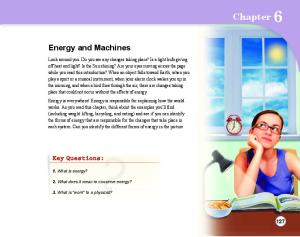
CHAPTER 13 Milling Methods and Machines 13.1 Introduction Modern milling machines look much the same as they did 25 years ago. However, they now must cut super alloys, titanium, and high tensile steels to closer tolerances and at faster rates then previously. To handle these requirements, the new milling machines provide higher horsepower, greater stiffness, and wider speed and feed ranges than before. In addition, more accurate lead screws, closer alignment, numerical control (NC) and computer numerical control (CNC) all result in faster work with better finishes and greater accuracy than ever before attained. A modern CNC vertical milling machine is shown in Figure 13.1
13.2 Types of Milling Machines The many types of milling machines used in manufacturing have been
George Schneider, Jr. CMfgE Professor Emeritus Engineering Technology Lawrence Technological University Former Chairman Detroit Chapter ONE Society of Manufacturing Engineers Former President International Excutive Board Society of Carbide & Tool Engineers Lawrence Tech.- www.ltu.edu Prentice Hall- www.prenhall.com
www.toolingandproduction.com
FIGURE 13.1: Modern CNC vertical milling machine (Courtesy Ingersoll Milling Machine Co.)
grouped into three general classes. • Column and Knee Machines • Bed Type Milling Machines • Special Purpose Machines The common subtypes are also identified and discussed.
13.2.1 Column and Knee Machines Column and knee milling machines are made in both vertical and horizontal types. The schematic diagrams (Fig. 13.2a and Fig.13.2b) show both types of machines. Versatility is a major feature of knee and column milling machines. On a basic machine of this type, the table, saddle, and knee can be moved. Many accessories such as universal vises, rotary tables, and dividing heads, further increase the versatility of this type of machine. Regardless of whether the machine is of the vertical or horizontal type, several components on all column and knee milling machines are similar, except for size and minor variations because of manufacturer’s preference. These similarities are described in terms of general shape, geometric relationship to the rest of the machine, function, and the material from which the components are made. Figure 13.3a shows a standard vertical milling machine and Figure 13.3b shows a 3 axis CNC vertical milling machine A universal Horizontal Column and Knee milling machine is shown in Figure 13.4. Column: The column, which is usually combined with the base as a single casting, is cast gray iron or ductile iron. The column houses the spindle, bearings, and the necessary gears, clutches, shafts, pumps, and shifting mechanisms for transmitting Chapter 13/Tooling & Production 1
Chap. 13: Milling Methods & Machines Motor
Arbor
Overarm
Overarm
Z′ Spindle nose
Y′
Outboard bearing and arbor support
Column
Table (X axis)
Quill X
Spindle Table
Saddle (Z axis)
Z
Z
Knee (Y axis)
Y
Column X
Saddle Y Knee
Elevating screw
Z′ Base
Elevating screw Base
(a)
(b)
FIGURE 13.2: Schematic illustration of the motions and components (a) of a vertical-spindle column and knee type milling machine and (b) of a horizontalspindle column and knee type of machine.
(a)
(b)
FIGURE 13.3: (a) Stand vertical-spindle column and knee type milling machine. (Courtesy Bridgeport Machinery, Inc.) (b) Three-axis CNC vertical-spindle column and knee type milling machine. (Courtesy Chevalier Machinery, Inc.)
power from the electric motor to the spindle at the selected speed. The gears usually run in oil and are made of carburized alloy steel for long life. Some of the necessary controls are usually mounted on the side of the column. The base is usually hollow, and in many cases serves as a sump for the cutting fluid. A pump and filtration system can be installed in the base. The hole in the center of the base houses the support for the screw that raises and lowers the knee. The machined vertical slide on the front of the column may be of the square or dovetail type. The knee moves up and down on this slide. The slide must be machined at a 90 degree 2 Tooling & Production/Chapter 13
angle to the face of the column in both the lateral and vertical planes. The tolerances are very close and are usually expressed in minutes or seconds of arc. The large hole in the face of the column casting is for the spindle. The hole is very accurately bored perpendicular to the front slide in two planes and parallel to the upper slide. Spindle: On a horizontal milling machine, the spindle is one of the most critical parts. It is usually machined from an alloy steel forging and is heat treated to resist wear, vibration, thrust, and bending loads. The spindle is usually supported by a combination of ball and straight roller bearings, or by tapered roller bearings that absorb both radial loads and end thrust loads.
FIGURE 13.4: A universal horizontalspindle column and knee type milling machine. (Courtesy Summit Machine Tool Manufacturing Corp.)
Spindles are hollow so that a drawbar can be used to hold arbors securely in place. The front of the spindle is machined to accept standard arbors. The two keys that fit into corresponding slots in the arbor do the actual driving of the arbor. The internal taper, which is accurately ground so that it is concentric with the spindle, locates the arbor. Knee: The knee is a casting that is moved up or down the slide on the front of the column by the elevating screw. Two dovetail or square slides are machined at 90 degrees to each other. The vertical slide mates with the slide on the front of the column, and the horizontal slide carries the saddle. It contains the necessary gears, screws, and other mechanisms to provide power feeds in all directions. The operator can select various feed rates with the controls mounted on the knee. Saddle: The saddle for a plain milling machine is a casting with two slides machined at an exact 90 degree angle to each other. The lower slide fits the slide on the top of the knee, and the upper slide accepts the slide on the bottom of the table. The surfaces of the slides that make contact with the knee and the table are parallel to each other. Locks for both the cross slide and table is fitted to the saddle, along with the nuts that engage with the cross feed and table feed screws. On a universal milling machine the saddle is made in two pieces and is more complex because it must allow the table to swivel through a limited arc. The lower part has a dovetail slide www.toolingandproduction.com
Chap. 13: Milling Methods & Machines
FIGURE 13.5: CNC bed type milling machine. (Courtesy WMW Machinery Co., Inc.)
milling machine is often ideal for this kind of work. In this machine the table is supported directly on a heavy bed, while the column is placed behind the bed. A CNC bed-type milling machine is shown in Figure 13.5. and an operational set-up with three spindles is shown in Figure 13.6. There are several advantages of the bed-type machine, particularly for production runs. Hydraulic table feeds are possible; the hydraulic components being housed in the bed casting. This allows very high feed forces; variable feed rates during any given cut, and automatic table cycling. The spindle may be raised or lowered by a cam and template arrangement to produce special contours. The basically heavier construction allows more power to be supplied to the spindle, which gives higher productivity through faster metal removal. Duplex bed-type milling machines have two columns and spindles for milling two surfaces on a part simultaneously. A large 5-axis CNC bed-type milling machine is shown in Figure 13.7. The chief disadvantage of a bed-type milling machine compared to one of the knee and column type is that it is less versatile for machining small parts. Its advantages lie in its higher productivity, its adaptability to large sized machines, and its ease of modification to special applications.
Acme thread. Milling machines with vertical spindles (see Fig. 13.3a), are available in a large variety of types and sizes. The head, which houses the spindle, motor, and feed controls, is fully universal and can be placed at a compound angle to the surface of the table. The ram, to which the head is attached, can be moved forward and back and locked in FIGURE 13.6: Machining operation showing a bed- any position. A turret on top of the column allows the type milling machine with three heads (Courtesy: head and ram assembly to Cincinnati Machine) swing laterally, increasing the reach of the head of the machine. that fits the top of the knee and a Some ram-type milling machines 13.2.3 Special Purpose circular slide above it is graduated in Milling Machines degrees for a small portion of its pe- can be used for both vertical and hoririphery. The upper portion of the zontal milling. On ram-type vertical As industrial products have become saddle consists of a circular face that mills that have the motor fits against the lower circular slide, a in the column, power is central pivot point, and a dovetail slide transmitted to the spindle that accepts the table. Locking bolts by gears and splined shafts. moving in a circular T-slot are pro- Some heavy duty vertical vided so that the two parts of the saddle mills have a spindle and head assembly that can be can be locked in any position. Table: Milling machine tables vary moved only vertically by greatly in size, but generally they have either a power feed mechathe same physical characteristics. The nism or manually. These bottom of the table has a dovetail slide are generally known as that fits in the slide on top of the over arm-type vertical saddle. It also has bearings at each end milling machines. to carry the table feed screw. The top of the table is machined parallel with 13.2.2 Bed-Type Milling Machines the slide on the bottom and has several High production calls for full length T-slots for mounting vises heavy cuts, and the rigidity or other work holding fixtures. A dial graduated in thousandths of of a knee and column type an inch is provided to allow for accu- of milling machine may rate table movement and placement. not be sufficient to take the FIGURE 13.7: Large 5-axis CNC bed type milling The table feed screw usually has an high forces. A bed-type machine. (Courtesy Ingersoll Milling Machine Co.) www.toolingandproduction.com
Chapter 13/Tooling & Production 3
Chap. 13: Milling Methods & Machines
(a) FIGURE 13.8: (a) Illustration of a planertype milling machine. (Courtesy Kennametal Inc.) (b) Part being machined on a planertype milling machine. (Courtesy Ingersoll Milling Machine Co.)
more complex, new and unusual variations of the more common milling machines have been developed. The objectives are to accommodate larger work, make many duplicate parts, locate holes and surfaces precisely, or to do other unusual machining jobs. Planer-Type Milling Machines: The general arrangement of these types of machines is similar to that for planers (Chapter 7), except that in place of individual tool bits, milling heads are installed. The table of the machine carries the work past the rotating cutter heads, which are individually powered and can be run at different speeds if necessary. As many as four cutter heads can be used, with two mounted on the cross rail and two on the vertical pillars. An illustration of a planer type milling machine is shown in Figure 13.8a. A part being machined on a
(b)
planer-type milling machine is shown in Figure 13.8b. Planer-type machines are used mostly for machining parts like the bedways for large machine tools, and other long workpieces that require accurate flat and angular surfaces or grooves. Profile Milling Machines: Two dimensional profiling can be done by using a template, or with a numerically controlled vertical milling machine. Some profilers have several spindles, and a number of duplicate parts can be produced in each cycle. Hydraulic-type profilers have a stylus that is brought into contact with the template to start the operation. The operator then moves the stylus along the template, causing hydraulic fluid under pressure to flow to the proper actuating cylinders. The table moves the work past
FIGURE 13.9a: Profile milling operation is shown, using a ball-nosed end milling cutter. (Courtesy Ingersoll Milling Machine Co.) 4 Tooling & Production/Chapter 13
the cutter, duplicating the shape of the template. A profile milling operation is shown, using a ballnosed milling cutter, in Figure 13.9a. A 5 axis, multi-spindle profile milling machine is shown in Figure 13.9b. Die sinking and other processes involving the machining of cavities can be done on three-dimensional profilers. An accurate pattern of the cavity is made of wood, plaster, or soft metal. The stylus follows the contour of the pattern guiding the cutter as it machines out the cavity. Numerically controlled milling machines are also used for this type of work.
13.3 Computer Controlled Machining Systems Several of the standard machines discussed in previous chapters of this text are capable of performing multiple operations. A lathe for example is capable of turning, facing, drilling, threading, etc. A drilling machine is capable of drilling, reaming, countersinking, tapping, and so on. However, when increased production rates require the purchase of additional machining capability, it is almost always more economical and feasible to purchase multifunctional ma-
FIGURE 13.9b: A large 5-axis multispindle profile milling machine. (Courtesy Cincinnati Machine)
www.toolingandproduction.com
Chap. 13: Milling Methods & Machines
turret tool holders or provides for automatic tool change. A tool holder magazine is shown in Figure 13.10 Machining centers are built in either horizontal or vertical configuration.
The relative merits of each will be discussed briefly. Horizontal Machines: Horizontal machines tend to be advantageous for heavy box-shaped parts, such as gear housings, which have many features that need to be machined on the side faces. The horizontal machine easily supports heavy workpieces of this type. If a rotary indexing worktable is added, four sides of the workpiece can be machined without re-fixturing. Pallet systems used to shuttle pieces in and out of the workstation tend to be easier to design for horizontal machines, where everything in front of the main column is open and accessible. A horizontal machining center with a pallet shuttling system is shown in Figure 13.11. Vertical Machines: Vertical machining centers are often preferred for flat parts that must have through holes. Fixtures for these parts are more easily designed and built for a vertical spindle. Also, the thrust of the cut developed in drilling or in milling pockets can be absorbed directly by the bed of the machine. The motions of a 3 and 5-axis CNC vertical machining center are shown in Figure 13.12. The vertical machine is preferred where three-axis work is done on a single face as in mold and die work. The weight of the head of a vertical machine as it extends away from the column, particularly on large machines, can be a factor in maintaining accuracy, as there may be some tendency for it to drop and lose accuracy and cause chatter. A vertical machining center is shown in Figure 13.13 and a machining center with an adjustable head, tool change magazine and a pallet system is shown in Figure 13.14
(a)
(b)
FIGURE 13.10: Preset machining center tools are stored in a toolholder magazine. (Courtesy Kennametal Inc.) FIGURE 13.11: Horizontal machining center with pallet shuttling system. (Courtesy Cincinnati Machine)
chines capable of quick changes, simultaneous machining, and automatic processing. The term “Automation” was coined in the 1950’s and applied to devices that automatically load and unload parts. The term is now accepted to cover, in addition to loading and unloading, functions such as processing, measuring workpiece size, adjusting a machine to maintain size, and repeating of workpiece cycles. Computer Controlled Manufacturing Systems discussed here will be Machining Centers and Flexible Machining Systems.
13.3.1 Machining Centers Machining centers are designed and built to provide for flexible manufacturing. They can be used to machine just a few parts or large production runs. Programming can be relatively simple and the use of ‘canned’ cycles provides a great deal of versatility. An NC machining center by definition is able to perform milling, drilling, and boring cuts and has either indexing www.toolingandproduction.com
FIGURE 13.12: The motions of (a) a 3-axis CNC vertical machining center and (b) a 5-axis CNC vertical machining center. (Courtesy Kennametal Inc.) Chapter 13/Tooling & Production 5
Chap. 13: Milling Methods & Machines
FIGURE 13.13: Transparent rendition of a vertical machining center. (Courtesy Monarch Machine Tool)
13.3.2 Flexible Machining Systems Flexible machining systems employ one or more machining centers, usually along with other equipment, to produce medium-volume workpieces. A workpiece-handling system is required, and a central computer typically controls the entire arrangement. A flexible machining system is shown in Figure 13.15. Material Handling: Parts are moved from storage and between machine elements by means of one of several different types of systems. The material-handling system selected must be capable of routing any part to any machine in any order and also to provide a bank of parts ahead of each machine to realize maximum productivity. Parts are normally loaded and unloaded manually. The various types of material-handling systems used include: automated guided vehicles, towline systems, roller conveyer systems, overhead conveyer
FIGURE 13.15: Flexible machining system. (Courtesy Sandvik Coromant Co.) 6 Tooling & Production/Chapter 13
FIGURE 13.14: Machining center with adjustable head, tool magazine and pallet system (Courtesy Cincinnati Machine)
systems, monorails, cranes and robots. An FMS material-handling system is shown in Figure 13.16. Control Systems: The computer controls of flexible machining systems have three functional levels Master Control – The master control monitors and controls the entire system, including routing workpieces to appropriate machines, scheduling work, and monitoring machine functions. Direct Numerical Control – A DNC computer distributes appropriate programs to individual CNC machines and supervises and monitors their operations. Element Control – The third and lowest level of control is computer control of the machining
cycles of individual machines.
13.4 Milling Machine Attachments and Accessories Many accessories have been developed for milling machines. Some are specialized and can be used for only a few operations. Others, such as vises, arbors, and collets, are used in almost all milling operations.
13.4.1 Special Milling Heads Several types of special heads have been developed for use on horizontal or vertical milling machines. These accessories increase the versatility of the machine. For example, a vertical head can be attached to a conventional horizontal column and knee milling ma-
FIGURE 13.16: FMS material-handling system. (Courtesy Giddings + Lewis LLC) www.toolingandproduction.com
Chap. 13: Milling Methods & Machines
(a) FIGURE 13.17: (a) Universal milling head attachment. (b) A universal milling head attachment being used on a horizontal milling machine. (Courtesy WMW Machinery Co., Inc.)
chine, greatly increasing its usefulness, especially in small shops with a limited number of machines. Vertical Heads: Vertical heads are generally attached to the face of the column or to the overarm of a horizontal milling machine. The head is a semi-universal type, which pivots only on the axis parallel to the centerline of the spindle, or it is fully universal. Fully universal heads can be set to cut compound angles. Both types of heads are powered by the spindle of the milling machine and accept standard arbors and collets. A universal milling head attachment is shown in Figure 13.17a.Figure 13.17b shows a universal milling head attachment being used on a horizontal milling machine. Rack-Milling Attachment: The rack-milling attachment bolts to the spindle housing of the milling machine. Its spindle is at a right angle to the main spindle of the machine. Both spur and helical racks can be milled with this attachment, and it can also be used to mill worms. Some rack-milling attachments have an outboard support for the spindle, which makes it possible to take heavier cuts. Slotting Attachment: This attachment that is bolted to the column of a horizontal milling machine can be swiveled 90 degrees in either direction from the vertical position. It is used primarily in toolmaking and prototype work for cutting keyways, internal splines, and square or rectangular cavities. The crank that actuates the reciprocating slide is driven directly by the spindle, and the stroke is adjustable. High Speed Attachment: When spindle speeds beyond the operating www.toolingandproduction.com
(b)
mum opening classify vises of this type. Cam-operated plain milling vises are widely used in production work because of the savings in time and effort and the uniform clamping pressure that can be achieved. Swivel-Base Vise: A swivel-base vise is more convenient to use than the plain vise, although it is somewhat less rigid in construction. The base, which is graduated in degrees, is slotted for keys that align it with the T-slots in the table. The upper part of the vise is held to the base by T-bolts that engage a circular T-slot. The swivel-base vise, when used on a milling machine with a semi-universal head, makes it possible to mill compound angles on a workpiece. Universal Vise: A universal vise (Fig. 13.18b) is used mostly in toolroom diemaking, and prototype work. The base of the vise is graduated in degrees and held to the table by Tbolts. The intermediate part of the vise has a horizontal pivot upon which the vise itself can rotate 90 degrees. Because there are several joints and piv-
range of the machine are necessary, high speed attachments can be placed on both horizontal and vertical milling machines. A gear train is generally used to step up the speed as much as 6 to 1, which allows more efficient use of small cutters.
13.4.2 Vises and Fixtures In all milling operations, the work is held by fixtures, vises, or clamping arrangements. In most cases the work is held stationary in relation to the table while it is being machined, but work held in indexing heads and rotary tables can be moved in two planes while machining operations are in progress. Plain Vise: Plain milling vises (Fig. 13.18a) are actuated by an Acme threaded screw, and the movable jaw moves on either a dovetail or rectangular slide. The vises are usually cast of high grade gray cast iron or ductile iron and can be heat treated. Steel keys are attached in slots machined into the bottom of the vise, parallel with and perpendicular to, the fixed jaw to allow accurate placement on the milling table. The jaw inserts are usually heat treated alloy steel and are attached by cap screws. The jaw width and maxi-
(a)
(b) FIGURE 13.18: (a) A plain vise. (b) A universal vise, which is generally used in a toolroom diemaking and protype work. (Courtesy Palmgren Steel Products, Inc.) Chapter 13/Tooling & Production 7
Chap. 13: Milling Methods & Machines and cannot be held easily in a vise. Holding fixtures, that are a combination of a simple angle plate and a collet, are sometimes used to hold round or hexagonal work for milling. The collet-holding fixture may be manually or FIGURE 13.19: Adjustable-angle tables can be tilted air operated. Both fixtures in one or more directions to machine irregularly can be bolted to the milling shaped parts. (Courtesy Palmgren Steel Products, table in the vertical or horiInc.) zontal position or attached to an adjustable angle plate for holding workpieces at simple or compound angles to the table or other reference surface. Indexing Heads: The indexing head, also known as the dividing head (Fig. 13.20), can be used on vertical and horizontal milling machines to space the cuts for such operations as making splines, gears, worm FIGURE 13.20: Indexing heads, also called dividing wheels, and many other parts requiring accurate division. heads, can be used on vertical and horizontal milling machines. (Courtesy Cincinnati Machine) It can also be geared to the table screw for helical milling operations such as cutting ots in the vise assembly, the universal flutes in twist drills and making helical vise is usually the least rigid of the gears. Indexing heads are of the plain or various types of milling machine vises. Angle Plates: Several types of universal type. Plain heads cannot be angle plates can be used to hold work tilted; universal heads can be tilted to or work holding fixtures for milling the vertical or any intermediate posi(Fig. 13.19). Plain angle plates are tion. The spindle of the indexing head available in T-slotted or blank form can be fitted with a chuck, or with and are usually strong iron castings. other work holding devices, including Adjustable angle plates may tilt in one collets or a center. A cross-sectional direction only or have a swivel base. view of an indexing head is shown in They are very useful for milling Figure 13.21. Most indexing heads have a worm workpieces that are irregular in shape FIGURE 13.21: Cross-sectional view of indexing head. (Courtesy Cincinnati Machine)
8 Tooling & Production/Chapter 13
(a)
(b) FIGURE 13.22: (a) Rotary tables can be used on both vertical and horizontal milling machines. (b) A rotary table, that can also be tilted. (Courtesy Palmgren Steel Products, Inc.)
and wheel reduction ratio of 40:1, requiring 40 turns of the hand crank to make the spindle revolve once. When the necessary index plates are available, all divisions up to and including 50 can be achieved by plain indexing. For some numbers above 50, differential indexing is necessary. In recent years, programmable precision indexers have become fairly common in shops doing work that requires accurate spacing of complex hole patterns on surfaces. The indexer may be mounted with the axis of the chuck vertical or horizontal, and in some cases the chuck may be replaced with a specially made holding fixture or a faceplate. If necessary, a tailstock may be used to support the end of the workpiece. The controller is capable of storing a series of programs, each of which may incorporate as many as 100 operational steps or positions. Rotary Table: Rotary tables (Fig. 13.22) are available in a wide range of sizes and can be used on both vertical and horizontal milling machines. Most can also be clamped with the face at a 90 degree angle to the surface of the milling machine table. The face of the rotary table has four or more Tslots and an accurately bored hole in the center, which is concentric with the axis about which the table rotates. The base of the rotary table, which www.toolingandproduction.com
Chap. 13: Milling Methods & Machines FIGURE 13.23: Schematic drawing of an arbor mounting with drawbolt used in horizontal milling machines.
Machine frame Bearings
Draw bar
Spindle nose
Arbor
Detail of Arbor Mounting
Several basic types of arbors and collets are used to hold milling cutters and to transmit power from the spindle to the cutter. Regardless of type, they are usually precisely made of alloy steel and heat treated for wear resistance and strength. Arbors: Arbors for horizontal milling machines (Fig. 13.23) are available in three basic types: style A, style B, and style C. A draw bolt, that goes through the spindle of the machine, screws into the small end of the taper and draws the arbor tightly into the tapered hole in the milling machine spindle. Power is transmitted from the spindle to the arbor by two short keys that engage with the slots on the flange
of the arbor. Style A arbors consist of the tapered portion that fits the spindle, the shaft on which the cutter or cutters fit, the spacers, and the nut. The shaft has a keyway along its entire length. The outboard end of the arbor has a pilot that fits into a bronze bushing in the outboard support of the milling machine overarm (Fig. 13.2b). One or more cutters can be mounted on the arbor, either adjacent to each other or separated by spacers and shims. Style A arbors are used primarily for light and medium duty milling jobs. Style B arbors are used for heavy milling operations, especially where it is necessary to provide support close to a milling cutter, such as in a straddle milling operation. One or more bearing sleeves may be placed on the arbor as near to the cutters as possible. An outboard bearing support is used for each bearing sleeve on the arbor. Style C arbors are used to hold and drive shell end mills (Fig. 25.25b) and some types of face milling cutters and require no outboard support. In some cases, they can also be fitted with adapters for mounting other types of cutters. Collets: On some vertical milling machines the spindle is bored to accept
(a)
(b)
houses the worm drive mechanism, is graduated in degrees, and the handwheel can be graduated in increments as small as 5 minutes or 1/12 of 1 degree. On some rotary tables an index plate may be attached to the base. Rotary tables can also be geared to the table feed screw. When set up in this manner, the rotary table can be used to make plate cams and to generate a number of other irregular shapes.
13.4.3 Arbors, Collets, and Tool Holders
FIGURE 13.24: (a) Collets of various sizes. (Courtesy Lyndex Corp.) (b) Various toolholders with collets and a setup fixture. (Courtesy Valenite Inc.) www.toolingandproduction.com
(a)
(b) FIGURE 13.25: (a) End milling cutter toolholders. (b) Shell end milling cutter toolholders. (Courtesy Lyndex Corp.)
a collet that has a partly straight and partly tapered shank. The collet is secured by a drawbar that is screwed into a tapped hole in the back of the collet and tightened from the top of the spindle. Some milling machine manufacturers offer collet arrangements that do not need a drawbar. Collets of this type can be closed with a lever-operated cam or with a large locking nut. Figure 13.24a shows various size collets and Figure 13.24b shows a number of tool holders including collets and a set-up fixture. Toolholders: Standard tool holders are available for end mills and shell mills as shown in Figures 13.25a and 13.25b respectively. For some operations that require the use of tools with non-standard shank sizes, chucks can be used to hold the tool. These chucks are available with Morse taper or straight shanks. Either type can be used in milling machines when the proper adapters or collets are available. Offset boring heads (Fig. 13.26) are Chapter 13/Tooling & Production 9
Chap. 13: Milling Methods & Machines FIGURE 13.28: Conventional or up-milling as compared o climb or downmilling.
FIGURE 13.26: Offset boring heads are often used in milling machines for boring, facing, and chamfering operations. (Courtesy Bridgeport Machine, Inc.)
often used in vertical milling machines for boring, facing, chamfering, and outside diameter turning operations. They are available with straight, Morse taper, or standard milling machine taper shanks and usually have three mounting holes for boring bars. Two of the holes are usually parallel with the centerline of the tool, and one is perpendicular to the centerline. Some boring heads have two adjusting mechanisms, and the movable slide can be adjusted accurately in increments of 0.0001 inch. Flycutters can be used for facing operations. The tools in cutters of this type are adjusted so that both a roughing and finishing cut are taken in one pass.
13.5 Types of Milling Operations Milling cutters are used either individually or in combinations to machine various surfaces as described below and shown in Figure 13.27. Plain Milling: Plain milling is the process of milling a surface that is parallel to the axis of the cutter and basically flat. It is done on plain or universal horizontal milling machines with cutters of varying widths that have teeth only on the periphery. Side Milling: For side milling, a
(a) Straddle milling
(b) Form milling
FIGURE 13.29: In gang milling operations, horizontal, vertical, or angular surfaces are machined in one path. (Courtesy Sandvik Coromant Co.)
cutter that has teeth on the periphery, and on one or both sides, is used. When a single cutter is being used, the teeth on both the periphery and sides may be cutting. The machined surfaces are usually either perpendicular or parallel to the spindle. Angle cutters can be used to produce surfaces that are at an angle to the spindle for such operations as making external dovetails or flutes in reamers. Straddle Milling: In a typical straddle milling set-up (Fig. 13.27) two-side milling cutters are used. A straddle milling operation is shown in Figure 13.28. The cutters are half-side or plain side milling cutters, and have straight or helical teeth. Stagger-tooth side milling cutters can also be used. The cutters cut on the inner sides only, or on the inner sides and the periphery. If the straddle milling operation involves side and peripheral
(c) Slotting
(d) Slitting
FIGURE 13.27: Drawing of a milling cutter showing the difference between advance per revolution (apr) and advance per tooth (apt). 10 Tooling & Production/Chapter 13
cuts, the diameter of the two cutters must be exactly the same. When cutters with helical teeth are used, the helix angles must be opposite. Since straddle milled surfaces must be parallel to each other and are usually held to close tolerances in terms of width, the condition and size of the collars and shims that separate the cutters are important. The arbor must also turn as true as possible to avoid cutting the workpiece undersize. Usually, a combination of collars and steel shims can be assembled to provide the correct spacing between cutters. For some production operations, a special collar can be made from alloy or medium-carbon steel, heat treated, and surface ground to length. The faces must be perpendicular to the bore and parallel to each other. The cutters should be keyed to the arbor, and the outboard bearing supports must be placed as close to the cutters as possible. Gang Milling: In gang milling, three or more cutters are mounted on the arbor, and several horizontal, vertical, or angular surfaces are machined in one pass (Fig. 13.29). When making a gang milling set-up, several different types of cutters can be used, depending on the job to be done. Cutters used for producing vertical or angular surfaces must be of the sidewww.toolingandproduction.com
Chap. 13: Milling Methods & Machines
(a) FIGURE 13.31: Face milling operation. (Courtesy Valenite Inc.)
(a)
(b)
(b) FIGURE 13.30: (a) Slotting operation used in the manufacturing of rotors. (Courtesy Iscar Metals, Inc.) (b) Slitting operation to separate cast automotive parts. (Courtesy Sandvik Coromant Co.)
cutting type; plain milling cutters of the proper width can be used for horizontal surfaces. In some cases face mills with the teeth facing inward can be used at one or both ends of the gang milling set-up. When only one wide plain helical milling cutter is used as part of a gang milling set-up, the side thrust caused by that cutter should be directed toward the spindle of the machine. If possible, interlocking cutters with opposite helix angles should be used to eliminate side thrust and reduce the possibility of chatter. Because of the time and effort involved in setting up the milling machine for gang milling, the process is used mainly for production work. Since all or almost all of the workpiece is being machined at one time, power and rigidity are very desirable features in the machine being used. Every effort should be made to control vibration, including the use of support bars that are bolted to both the knee and the outboard bearing support. Form Milling: The number of parallel surfaces and angular relationships www.toolingandproduction.com
FIGURE 13.32: End milling operation. (Courtesy Valenite Inc.)
FIGURE 13.33: Milling operations: (a) side and face milling cutters used to machine various slots, (b) various indexable milling cutters used to machine an automotive engine block. (Courtesy Sandvik Coromant Co.)
that can be machined by peripheral milling is limited almost only by cutter design. Form cutters are expensive, but often there is no other satisfactory means of producing complex contours as shown in Figure 13.27. Slotting and Slitting Operations: Milling cutters of either the plain or side-cutting type are used for slotting and slitting operations (Fig.13.30a and 13.30b). Slotting and Slitting are usually done on horizontal milling machines, but can also be done on vertical mills by using the proper adaptors and accessories. Metal slitting cutters of various diameters and widths are also used to cut slots. A number of identical cutters can also be mounted on the same arbor for cutting fins. When the thickness of the fins must be held to
close tolerances, spacers are usually machined and surface ground to provide the necessary accuracy. Face Milling: Face milling (Fig. 13.31) can be done on vertical and horizontal milling machines. It produces a flat surface that is perpendicular to the spindle on which the cutter is mounted. The cutter ranges in size and complexity from a simple, single-tool flycutter to an inserted-tooth cutter with many cutting edges. Large face mills are usually mounted rigidly to the nose of the spindle. They are very effective for removing large amounts of metal, and the workpiece must be securely held on the milling table. End Milling: (Fig. 13.32) End milling is probably the most versatile milling operation. Many types of end mills can be used on both vertical and
(a)
(b)
FIGURE 13.34: Two turn milling operations. (Courtesy Sandvik Coromant Co.) Chapter 13/Tooling & Production 11
Chap. 13: Milling Methods & Machines horizontal milling machines. End mills are available in sizes ranging from 1/32 to 6 inches (for shell end mills) and in almost any shape needed. Milling cutters can be used individually or in pairs to machine various slots (Fig. 13.33a). Many milling cutters can also be mounted onto an arbor to perform in a gang milling operation of automotive engine blocks as shown in Figure 25.33b
13.6 Turn Milling Turn milling consists of a number of
12 Tooling & Production/Chapter 13
different machining methods where a milling cutter machines a rotating workpiece. These methods are primarily used for machining various eccentrically shaped parts; planes, tapered and cylindrical surfaces; grooves and inside holes. Turn milling requires a machine tool with certain functions and a number of axes. Machining centers, turning centers, specially adapted lathes, milling machines, boring mills and specialpurpose machines are used. When other operations of turning and milling
are combined in the machines, single set-up machining leads to advantages of fast through-put times and flexibility of production. Two turn milling operations are shown in Figure 13.34a and Figure 13.34b. Advantages associated with turn milling are: capability of machining large and unbalanced parts which cannot be rotated at high speeds; complex surface shapes, eccentric parts and components with additional elements that protrude; log, unstable shafts or thin-walled parts.
www.toolingandproduction.com