Reprinted with permission from Aircraft Maintenance Technology, July 1999
Boosting Your Knowledge of Turbocharging (Part 1 of a 2 part Series) By Randy Knuteson
A
short 15 years after Orville and Wilbur made their historic flight at Kitty Hawk, General Electric entered the annals of aviation history. In 1918, GE strapped an exhaust-driven turbocharger to a Liberty engine and carted it to the top of Pike’s Peak, CO — elevation 14,000 feet. There, in the crystalline air of the majestic Rockies, they success-
A i r c r a f t
fully boosted this 350 hp Liberty engine to a remarkable 356 hp (a normally aspirated engine would only develop about 62 percent power at this altitude). An astounding altitude record of 38,704 feet was achieved three years later by Lt. J.A. Macready. This new technology began immediately experiencing a rapid evolution with the full
M a i n t e n a n c e
T e c h n o l o g y
•
strength of blowers being tested during WWII. The B-17 and B-29 bombers along with the P-38 and P-51 fighters were all fitted with turbochargers and controls. Turbocharging had brought a whirlwind of change to the ever-broadening horizons of flight. Much of the early developments in recip turbocharging came as a result of demands O C T O B E R
1 9 9 9
2
Recip Technology
from the commercial industrial diesel engine market. It wasn’t until the mid-1950s that this technology was seriously applied to general aviation aircraft engines. It all started with the prototype testing of an AiResearch turbocharger for the Model 47 Bell helicopter equipped with the Franklin 6VS-335 engine. Their objective was not to increase power, but rather to maintain sea level horsepower at altitude. They succeeded. In the process, a new altitude record for helicopters of 29,000 feet was achieved. Shortly afterward, the Franklin Engine Company entered receivership and in 1961, Bell ended up with a production helicopter powered by a Lycoming TVO-435. Coinciding with these developments were Continental’s efforts to develop their TSIO-470-B (Cessna 320) and GTSIO-520 (Cessna 411). Concurrently, efforts were also being made by TRW and later Rajay to provide 65 STCs to retrofit engines and airframes for approximately two dozen aircraft. Early OEM installations of these systems included the factory installed Rajay in Piper’s Commanche and Twin Commanche. Other original equipment installations included the Piper Seneca, Turbo Arrow, Enstrom Helicopter, Mooney 231, and Aerostars.
Turbo-normalized or groundboosted? Distilled to the most basic of definitions, a turbocharger is simply an air pump powered by the unused heat energy normally wasted out the exhaust. This “air pump” (or more accurately, compressor), is capable of supplying the engine intake manifold with greater than atmospheric air pressures. A collateral benefit is derived as the turbo also provides air for the cabin pressurization of certain aircraft. Some confusion persists as to the difference between an airplane that is “ground-boosted” as opposed to one that is “normalized.” Simply put, turbocharging serves one of two purposes: either it directly increases (boosts) the power output of the engine, or it assures that sea level horsepower performance is maintained (turbo-normalized) to higher altitudes, thereby increasing the plane’s potential service ceiling. A “normalized” turbo installation like the Rajay system in no way increases the normal engine RPMs, loads, or BMEP limits already established as safe for the engine. Instead, it merely assures that sea level performance is
A i r c r a f t
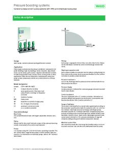
Percentage of HP Available At Altitude 100% 90%
Turbocharge
80% 70% 60%
No
50%
n-T
urb
oc
ha
40%
rge
30% 20% 10% 25 50 75 100
150
200
250
300
350
Altitude (X100) * Percentage based on full throttle, maximum RPM, standard day temp.
This graph illustrates the dramatic disparity between turbocharged and non-turbocharged aircraft engines. to bring these temperatures down and recapture some of this power loss while suppressing detonation. An engine relying on manifold pressures greater than ambient on a standard day is considered a “boosted” system. These engines require manifold pressures ranging from 31.0 to 45.0 inches HgA. Installations incorporating intercoolers demand an additional 2 to 3 inches HgA to compensate for the pressure loss in air flow through the intercooler. Common installations include TCM’s TSIO-520s in the Cessna 210 and Lycoming’s TIO 540 and 541 installed in Navajos, Turbo Aztecs, and Dukes, to name a few. These engines require reduced compression ratios (to provide wider detonation margins) since they produce more than normal sea level manifold pressures while in the take-off and climb configuration. Basically, the ultimate goal of turbocharging is to gain more power or to increase the efficiency of the engine without enlargdefinitions, ing the powerplant.
maintained at altitude without the customary diminishment of power. An engine that sustains but does not exceed 29.5 inches of manifold pressure at altitude is said to be normalized. “Critical altitude” is that point above which the turbocharger can no longer maintain maximum rated manifold pressure. However, just because an engine maintains 29.5 inches of MAP and redline rpm, does not necessarily mean it is developing sea level power. Depending on the application, compressor discharge air at critical altitude may be as hot as 250 to 300 degrees Fahrenheit. An increase in induction air temperatures of 6 to 10 degrees Fahrenheit decreases horsepower by roughly 1 percent. So, an airplane with a critical altitude of 25,000 feet may be producing only 80 percent power even though sea level manifold pressure is indicated at that altitude. An intercooler serves the purpose of a heat exchanger
“
Distilled to the most basic of
a turbocharger is simply an air pump
Design differences
powered by the unused heat energy
Turbochargers manufactured by Rajay and Garrett are very similar. Perhaps the most striking difference is their compara-
normally wasted out the exhaust.
M a i n t e n a n c e
”
T e c h n o l o g y
•
O C T O B E R
1 9 9 9
3
Recip Technology
tive size. Rajay units weigh 12 pounds while the Garrett turbos weigh from 15 to 43 pounds. These radical size variances are associated with engine size and applications. For instance, the TAO4 Garrett and the Rajay Turbos are typically installed in 180-230 hp engines. Compressor diameter in these models vary from 2.755 inches to 3.0 inches. In the Aerostar, twin turbos of this size are used. Both TCM’s earlier model 310P in the Malibu, and the Lycoming powered Mirage, also use this dual turbo arrangement. The TEO6 turbocharger is used to boost the performance of the 520s and 540s in the 275 to 350 horsepower category. While the 340s, 414s, and Navajos rely on a larger compressor wheel of the TH08 turbocharger to provide the additional bleed air for cabin pressurization. Internally, the bearing design of the Rajay is that of a “semi-floating” journal bearing. While the Garrett design incorporates dual bearings that turn at half of the turbine wheel speed. Instead of a ductile cast-iron bearing housing, Rajay’s housing is manufactured from aluminum. Both turbo lines depend on the Rajay (formerly Garrett AiResearch) valves and controllers to monitor turbo discharge and to determine manifold pressure. There are exceptions; however, most noticeably TCM’s “fixed” wastegate in their Seneca and Turbo Arrow models, and the Rajay manual wastegates and controllers.
Increased efficiency in a rarified atmosphere At sea level, the atmosphere in which we live and breathe is continually under a pressure of about 29.92 inches of mercury (Hg). At 1,000 feet, this “free air” drops in pressure to about 28.86 inches Hg. Air becomes progressively less dense at all altitudes above sea level. Because of this, all naturally aspirated engines experience a reduction of fullthrottle, sea level power output as they increasingly gain altitude. On a “standard day,” atmospheric pressure at 10,000 feet hovers at only 20.5inches Hg. In these conditions, a naturally aspirated engine is unable to sustain full power performance due to the lack of air density at these higher altitudes. Without the aid of a turbocharger, a loss of 3 to 4 percent of power or approximately 1 inch of MAP per 1,000 foot gain in altitude seems to be the rule. With the fuel to air ratio remaining constant, the amount of power developed by an
A i r c r a f t
Surge Line
Area of Peak Efficiency
RPMS
Turbocharger compressor performance map for Orenda OE600A engine — 600 hp at sea level take-off. This compressor can provide pressurized airflow for 500 engine horsepower at altitudes in excess of 25,000 feet. The left side of the map is referred to as the “Surge Area” where pressure and flow is unstable. The center “Island” represents the area of peak efficiency. As a rule, the broader the range of the compressor, the lower the peak efficiency. engine is directly proportionate to the mass of air being pumped into the engine. On a nonturbocharged engine, an increase in airflow is achieved by changing the throttle angle to increase MAP, or prop-pitch to increase RPM. The atmospheric limitations of density altitudes coupled with the mechanical limitations of the engine and propeller pose as restrictions to engine speeds. Some means of forcefeeding the engine additional air is required to overcome these limitations.
Re-claiming wasted energy As much as one-half the total heat energy from the engine is lost through the exhaust as a natural by-product of the combustion process. A portion of this heat energy is recovered by harnessing the hot expanding exhaust gases and re-routing them through the turbocharger. These gases enter a radial inflow turbine housing, striking the blades of the Inconel turbine wheel and exiting the turbine housing outlet. This flow of gas provides the necessary thrust that enables the turbine wheel to rotate at high speeds. Since these exhaust
M a i n t e n a n c e
T e c h n o l o g y
•
gases are normally wasted, little power is robbed from the engine to drive the turbine. A centrifugal compressor is connected to the turbine wheel by a common shaft, enabling it to rotate at the same speed as the turbine. The impeller draws in filtered air, compresses and delivers it to the cylinders where each pound of fuel is mixed with about 14.8 pounds of air (stoichiometric or peak EGT). In reality, however, proper engine management dictates that most engines be operated 100 to 125 degrees rich of peak EGT, thereby altering this ratio. Wheel configuration and size, housing size, and shaft speed all determine the pressure and volume of air delivered to the engine. Reams of data compiled by the engine manufacturers outline their desired parameters for the turbochargers and control systems to be used on their reciprocating engines. Design engineers then analyze this information, basing performance predictions on expected temperature and pressure changes in the manifold, the induction and exhaust ducting, as well as the pressure drop across the throttle and through the intercooler. The placement
O C T O B E R
1 9 9 9
4
Recip Technology
and orientation of the air intake, the exhaust by-pass valve, and cabin air-bleed must be factored in. The parameters of BHP (brake horsepower), turbine inlet temps, bypass flow and compressor discharge temps are only a few of the elements plotted against altitude for selected manifold pressures. Finally, flight-testing verifies or invalidates the assumptions of expected engine performance. Continued analysis is made, errors are corrected, assumptions are cross-checked, and the accuracy of the data is refined with a high probability of obtaining the desired aircraft performance. The goal is to use little or none of the engine’s horsepower to drive the turbocharger. Consequently, when proper engine installation and matching is done, mechanical loads imposed on the engine to power the turbo are minute. Most of the work required to drive the turbine is recovered from the exhaust gases. Otherwise, if the turbocharger was not in the system, this portion of the gas energy would be lost with discharged exhaust gases.
Maintenance of the turbocharger The turbocharger itself is subjected to an extremely hostile environment. Turbine inlet temperatures reach a scorching 1,650 degrees. Some are hotter still. TCM’s liquid-cooled Voyager is rated at 1,750 degrees continuous with the capability of 1,800 degrees for 30 seconds while establishing peak EGTs. Turbine speeds range from 0 to 120,000 rpm. The T36 in the Malibus and the Lancair 4P is capable of 125,000 at 1,650 F. That’s a screaming 2,083 revolutions per second! Pulsing exhaust gases, engine vibration and temperature variations all add to this hellish mix. The turbo assembly is made of the strongest of alloys available to withstand these rigorous conditions. However, these tortuous duty cycles can shorten the life of a turbo if proper maintenance is not performed. It is of the utmost importance to follow the maintenance and inspection criteria spelled out in the applicable service bulletins and airworthiness directives. Oil contamination, oil supply problems, FOD damage, and abrupt temperature changes are the chief contributors to premature turbocharger failures. There can not be enough emphasis placed on the importance of keeping the oil clean. Remember that the oil used to lubricate and cool the turbocharger is
A i r c r a f t
A classic example of turbine wheel damage caused by a piece of exhaust valve face. This demonstrates the importance of examining the condition of the turbine side of the turbocharger whenever cylinder or exhaust system maintenance is required. the engine oil. At high rpms, dirty oil that results from combustion by-products and the carbon residue from coking can dramatically shorten the life of a turbo. Although engine manufacturers recommend oil changes at 50hour intervals, many engine overhaul shops suggest a more conservative interval of 25 to 35 hours with turbocharged engines. Restrictions in the oil supply to the turbo result in a reduction of oil flow and subsequent overheating of the bearing(s) or center housing. Oil starvation can be caused by bad gaskets, restricted oil flow or improperly positioned orificed T-fittings. A classic example is the restricted T-fitting in the oil inlet line on Cessna’s 210, 206, 207, and 337s. The restricted side of this fitting is meant to feed the oil pressure gauge, not the turbo. The turbo side of this fitting is unrestricted. Unfortunately, it occasionally gets plumbed incorrectly. At all 100-hour inspections, remove the induction air supply duct to the compressor and the separate the exhaust outlet ducting from the turbine side. Check the compressor and turbine wheel blades for potential foreign object damage. Also, examine the outer tips of the blades and adjacent housing surfaces for any evidence of drag or rubbing.
M a i n t e n a n c e
T e c h n o l o g y
•
Turn the wheels by hand while exerting an end and side-load. There should be no rubbing or binding of the wheels against the housings and they should be free to rotate. Be certain to check the turbine housing for cracks and the security of the exhaust housing bolts, the lock tabs and the condition of the “V” band clamps. Special attention should be given to the manufacturer’s recommendations for proper “V” band installation procedures and appropriate torque values. A preventative maintenance procedure that should be practiced universally is to allow the engine to sufficiently warm up before applying full power, and to avoid pulling power abruptly. It’s also advisable to allow the engine to idle an additional three to five minutes prior to shutting it down. This allows the turbo to cool down and equalize temperatures before going to idle cut-off. These simple measures will reduce the possibility of oil residue coking in the hot turbine housing and should prolong the life of the turbo. It’s only as you consider the operational demands and the exacting details that factor into the analytical performance predictions in designing these systems that you gain a true appreciation for aircraft turbocharging.
O C T O B E R
1 9 9 9
5
Reprinted with permission from Aircraft Maintenance Technology, October 1999
Recip Technology
Boosting Your Knowledge of Turbocharging (Part 2 of a 2 part Series - Values and Controllers) By Randy Knuteson
A
ll normally aspirated aircraft engines gain altitude at the expense of horsepower. Approximately three percent of horsepower is lost or traded for every 1,000 feet of altitude gained; as altitude increases, performance wanes. The obvious advantage of any turbocharged aircraft is its ability to compensate for this loss and provide maximum rated power at altitude. This advantage gives the pilot the ability to over-climb inclement weather, achieve optimum altitudes and attain maximum speeds with relative ease. To fly high and fast in a pressurized cabin while experiencing smooth air and favorable winds is very desirable. Reduced drag, increased range, and improved fuel economy are just a few of the benefits turbocharging offers. In our previous discussion (July issue of AMT), we focused solely on the turbocharger
itself — that component which at altitude supplies additional power to otherwise anemic performing engines. We determined that pulsing exhaust gases provide the requisite force to drive the turbine wheel and consequently, the compressor, to speeds of up to 2,000 revolutions per second. The end result — exhaust energy is converted to manifold pressure. We also discovered that the turbocharger is subjected to the extremes of temperatures and duty cycles and that consistent oil changes, cool-down practices and maintenance are essential to its continued performance, health and operation. Turbochargers are indeed a remarkable feat of engineering ingenuity. And when coupled with their supporting wastegates, controllers, relief valves, oil lines and piping they can seem both confusing and intimidating. Occasionally, even the seasoned mechanic becomes frustrated to the point of literally “throwing in the wrench” on these systems. However, armed with just a bit of knowledge, charge-air systems can . . . turbochargers require some means of be reduced from extremely daunting to simply challenging. Perhaps the control. It becomes obvious that each turbo following information will equip you to feel up to the challenge as we control system chosen for a specific airplane attempt to clarify some of the annoying and at times confusing nuances has its own unique peculiarities. of turbocharging systems. Our dis-
“
”
A i r c r a f t
M a i n t e n a n c e
T e c h n o l o g y
•
cussion will focus on the individual components coupled with an explanation as to how they interrelate to each other.
Pressures to Perform As their names suggest, Valves and Controllers both regulate and control turbocharger discharge pressure. This is an exacting science due to the fact that there is a disproportionate air/fuel ratio that must be tailored to the ever-changing demands of the engine as well as atmospheric density changes. For these reasons, a means of managing this forced air-flow to the cylinders is necessary to prevent the onset of detonation or overboost. The control portion of the turbocharging “system” was designed for this purpose. Valves and controllers provide the desired flight envelop, while keeping engine intake manifold temperatures and exhaust manifold pressures as low as possible.
Deck Pressure and Manifold Pressure A basic knowledge of the air pressures associated with turbocharging is necessary for a more thorough understanding of these control systems. Air upstream of the throttle plate is often referred to as “Upper Deck Pressure.” Deck pressure is measured between the compressor discharge and the inlet to the fuel injector or carburetor. Pressure downstream of the O C T O B E R
1 9 9 9
6
Recip Technology
throttle is referred to as “Manifold Pressure” and is referenced between the throttle plate and the cylinder intake. A pressure drop occurs across the throttle plate and is dependent upon the position of the throttle angle. Deck pressure always exceeds manifold pressure. At wide-open throttle, the air pressure drop across the throttle plate is at its minimum (as little as 1/4 in. HgA). And conversely, as the throttle is closed, this pressure drop increases. These pressures change both in response to throttle movements and variations in air density and temperatures. Air density is a function of both pressure and temperature. Therefore, air temperatures influence the upper deck and manifold pressures. As you recall, as air is compressed, it increases in temperature, resulting in a reduction of air density and consequently a loss of engine power. A natural reduction of air density also occurs at higher altitudes and at temperatures above standard, which further exacerbates this problem. The compressor is forced to work harder to feed a sufficient amount of air to the cylinders. Excessive heat becomes the undesirable by-product of this exchange. Generally, there is a loss of one percent of horsepower for every 6 to 10 degrees increase in induction air temperature. Remember, engine power is influenced not only by rpm and manifold pressure, but also by induction air temperature. In certain installations an intercooler acts as a heat exchanger to cool down this discharge air and recapture lost power.
The need to control Intake air pressures and temperatures must be controlled since they have such a direct influence on engine performance. The Controller’s purpose is twofold: to sense changes in the upper deck and intake mani-
fold pressures and to keep engine power constant as ambient conditions vary. Some engines rely on more than one controller to perform this task. Controllers may be found in multiples or combined in a common housing. Regardless of the arrangement, they operate in parallel, even while responding to differing stimuli. Depending upon their installation, controllers may be plumbed directly into the upper deck air-stream or remotely mounted and referenced by means of hoses.
Automatic controllers The automatic controller monitors deck, manifold, and/or ambient pressures by means of a pressure differential across the diaphragm or by using a bellows calibrated to a predetermined absolute pressure. As the controller senses pressure changes, it seeks to modulate turbo output by regulating the amount of oil allowed to bleed past a poppet valve also housed within the controller. The movements of the diaphragm or the expansion and contraction of the bellows within the controller alters the position of this oil metering poppet valve in relation to a seat. As this poppet closes, oil flow back to the sump is restricted. Oil begins to dam upstream and exert a force against a piston in the wastegate actuator. This piston is mechanically linked to the wastegate valve and begins to close the valve. As the controller poppet moves, it becomes an adjustable orifice regulating the buildup of oil pressure that is exerted against a piston in the wastegate actuator. By altering the position of the wastegate valve, it controls the amount of exhaust gases either routed to the turbo or diverted out the exhaust, thus maintaining a pre-selected manifold pressure setting (see diagram 1, following page). In this manner it schedules the appropriate amount of air to the engine at any given altitude or power setting. The controller(s) could be appropriately thought of as the brains or command center for the entire charge-air system. As engine power, speed, or altitude is changed, the controller constantly strives for equilibrium within the system. The exhaust bypass valve (wastegate assembly) simply acts as a slave to the dictates of the controller. Engine oil becomes the muscle of the system, providing the power to actuate the movements of the wastegate assembly.
Comparative graph illustrating the advantage of turbocharging over naturally aspirated engines. This chart also demonstrates the differences found between the three distinct wastegate arrangements.
Design differences Lycoming engines utilize four basic styles of controllers: the Differential, the Density, the Variable Pressure and the Slope Controllers. The density controller is the only controller capable of sensing changes in temperature. It relies on a bellows charged with dry nitrogen to accomplish this purpose. Density controllers are found in the Piper Navajo and Chieftain and a handful of helicopter applications. In the Piper, the density controller modulates the wastegate movement at wide open throttle while a differential controller keeps deck pressures from exceeding manifold pressures by more than a specified amount at part throttle settings. Density controllers are extremely sensitive to in-field adjustments. A 1/16th turn of the adjustment screw will result in a 2-in. change in manifold pressures. A thermocouple probe referenced to deck temperature is required when setting up these systems (see Lycoming S.I. No. 1187J). Raytheon Aircraft’s turbocharged Barons, Bonanzas, and Dukes depend on a Variable Absolute Pressure Controller. The VAPC has a bellows that extends into the upper deck air stream, sensing deck pressure and comparing it to a referenced absolute pressure. What makes this controller “variable” is that it is linked directly to the engine throttle. Through a system of cams and followers, it adjusts a moveable poppet seat and accordingly achieves the optimum deck pressure for a given throttle setting.
Examples of Valves and Controllers
A i r c r a f t
M a i n t e n a n c e
T e c h n o l o g y
•
O C T O B E R
1 9 9 9
7
Recip Technology
Exhaust bypass valves: butterfly, poppet and fixed. Note that Continental’s “fixed” wastegate system relies on an adjustment screw in the turbine bypass pipe (right). Ground adjustments are made by loosening the lock nut and turning the screw into or out of the wastegate bypass pipe.
Continental’s turbocharged engines rely on absolute, variable absolute, pressure ratio, dual, or slope controllers. Dual controllers are a hybrid combination of absolute controllers coupled with a rate or ratio controller. These units are housed in a common body and were most frequently used in the older Cessna 200300-, and 400-series engines. TCM equipped Piper Malibus, the TSIO-550 equipped experimental Lancair IV, Piper’s new PA-32 and Cessna’s new 206’s all incorporate yet another style of controller — the sloped controller. The sloped controller incorporates the functions of an absolute pressure controller and a differential controller in a single housing. Acting much like the density and differential arrangement in the Navajo, the sloped controller maintains the rated deck pressure at wide-open throttle, and a reduced deck pressure at part throttle, and looks for discrepancies in the differential between deck and manifold pressures. If either pressures rise above a pre-determined value for a given throttle setting, the sloped controller opens the exhaust bypass valve, thereby lowering compressor speed and output. However, unlike the density controller, it does not correct for temperature excursions.
Manual control systems Not all turbocharging systems are automatically actuated. Instead, systems like those found in the Turbo Arrow and the Mooney 231 have a simple, built-in exhaust leak upstream
A i r c r a f t
of the turbo that allows a fraction Diagram 1: Schematic diagram showing the functional of the exhaust gases to be dumped operation of the type of turbocharging system found commonly on Raytheon’s Duke, the Cessna P210, 340, overboard and the remainder to be 414, 421, Piper’s Malibu and pressurized Navajo. routed through the turbine. This “fixed” wastegate arrangement has inches of Hg during throttle advancement. also been successfully used in the Seneca II-IV. To compensate, pilots were instructed to Other systems rely on manual inputs from the slowly advance the throttle to 32-in., wait pilot. As power begins to decrease at higher for a few seconds, and then continue to the altitudes with the throttle in the wide-open rated 35-in. of MAP. This surge in overboost position, the pilot then incrementally adjusts was dramatically reduced to 2 to 3 inches of the wastegate toward closure utilizing a sepaHg with the development of the GTSIO-520 rate vernier wastegate control cable. Or, as in engines. By modifying the bore size of the the case of Cessna’s Turbo Skylane and Piper’s wastegate actuator, designers found they Turbo Saratoga, some installations have the could minimize the time it took for oil diswastegate linked directly to the throttle. As the placement and wastegate actuation. wastegate valve closes, backpressure forces Safeguards are required to prevent the additional exhaust gases through the turbine overboosting of an aircraft engine. wheel assembly and speeds up the compresOverboosting occurs whenever maximum sor. This series of events results in an increase rated manifold pressures are exceeded. in engine manifold air pressure and a resulting Properly adjusted controllers and proper increase in power. The pilot becomes the “conthrottle management serve to preclude the troller” of these systems as he systematically onset of overboost. However, despite these monitors and regulates manifold pressures measures, inadvertent overboost still hapwhile ascending/descending in altitude. These pens. An incidence of overboost can take simplified manual systems reduce both cost place when the engine oil has not yet and complexity, albeit at the expense of reached operating temps and the throttle is increased pilot workload. This type of arrangerapidly advanced for takeoff or when a pilot ment is often used in aftermarket turbo-noron short final quickly advances the throttle malizing kits. for a go-around and the prop governor lags Overshoot/Overboost or the wastegate sticks. Overboost can also During the early stages in the developoccur at full throttle and below critical altiment of these systems, problems arose with tude when exhaust gases expelled are more momentary overboost of as much as 6 to 10 than capable of driving an uncontrolled
M a i n t e n a n c e
T e c h n o l o g y
•
O C T O B E R
1 9 9 9
8
Recip Technology
mally held in the closed position by a spring/bellows combination. It is set to off-seat at approximately two inches above normally rated MAP. Continental Motors compares the operation of this spring-loaded valve to a safety valve in a steam boiler. As excessive pressure builds, the valve opens and stays open until the manifold pressure again falls within acceptTwo styles of PRVs. The valve on the right has an external non-damped spring which is a separate able limits. The aneroid-style bellows part surrounding the bellows. The valve on the left allows the valve to “crack” open at a is designed for high-vibration environments. The specified pressure regardless of the spring is encased within the bellows assembly that is operational altitude of the engine. partially oil-filled to provide vibration damping. In the Mooney 231 (TSIO-360compressor to engine damaging speeds. GB/LB), and the Piper Turbo Arrow and What differentiates between Overshoot Senecas (TSIO-360-E/EB/F/ FB/KB), the and Overboost? Answer: Duration, or the Absolute Pressure Relief Valve functions as a length of time manifold pressures exceed turbocharger control/boost limiter. These their maximum rate. “Overshoot” occurs engines incorporate a “fixed” wastegate when manifold pressure increases above arrangement and do not rely on other servo maximum rate by one or two inches, and control systems. In this design, the PRV is set then returns immediately to the maximum to vent any compressor discharge pressures rated. Lycoming states that if overshoot exceeding one inch Hg above rated manidoes not exceed two inches and three secfold pressure. This “crack” pressure increasonds duration, it may be disregarded. TCM es as a function of altitude, thereby mainsays, “If the amount of overboost is from taining a constant manifold pressure as relief three to six inches, the system should be flow past the valve head varies. This “modchecked immediately for necessary adjustulating” valve successfully compensates for ments or replacement of the malfunctioning variations in compressor discharge air-flow. component.” As defined by Textron Lycoming, “momentary overspeed” is “an increase of no more than ten percent of rated engine RPM for a period not exceeding three seconds.” A table for computing overspeed by engine model is included in Lycoming SB#369I. Stringent inspection criteria are specified for engines subjected to inadvertent overspeed. These procedures include a thorough examination of the cylinders, Kelly Aerospace Power Systems is in the valves, guides, seats, counterweights, etc.
How do you spell relief?…P.R.V. The Pilots’ responsibility is to ensure that manifold pressures stay within their prescribed limits. But, humans are known to be fallible. With this in mind, thoughtful engineers sought to incorporate a secondary safety feature known as an absolute Pressure Relief Valve (“pop-off valve”). This valve is strategically positioned between the compressor outlet and the fuel injector/carburetor to prevent engine-damaging surges in manifold pressure. The valve head is nor-
A i r c r a f t
process of developing the next generation of turbocharger control systems. This state of the art electronic controller/wastegate configuration will provide a direct replacement for the current hydraulic-style controllers. The actuating motor will be retrofittable to existing models. This system is capable of operating in temperatures from 50 to 300 degrees F with humidity ranging from 0 to 100 percent at pressure altitudes up to 30,000 feet. Both controller and wastegate will be FAA certified for usage in single and multi-engine, pressurized and non-pressurized aircraft. Cost will be comparable to hydraulically activated systems.
M a i n t e n a n c e
Kelly Aerospace Power Systems will be offering its Aircraft Turbocharger Valve and Control Troubleshooting Reference Guide and its newly revised and updated Overhaul Manual for Valves and Controllers by year end.
A Compromise Between Cost and Performance As noted earlier, turbochargers require some means of control. It becomes obvious that each turbo control system chosen for a specific airplane has its own unique peculiarities. The final choice of system depends mainly on the desired altitude characteristics of that specific airplane. Engine horsepower, turbocharger speed limitations, cabin pressurization, and cost all become critical deciding factors in this equation. While a complete integration of the control system to the turbocharger is desired, occasionally the choice becomes a compromise between cost considerations and performance characteristics. Admittedly, this information only provides a cursory understanding of these systems. A more complete appreciation of turbocharger control systems can be had by studying the RAJAY (previously GARRETT) Turbochargers, Valves and Controls Troubleshooting Reference Guide. This brief but complete guide is available on request from Kelly Aerospace Power Systems. The troubleshooting guide along with newly updated Valve/Controller Overhaul Manual will be made available by year’s end.
Randy Knuteson is Director of Product Support for Kelly Aerospace Power Systems in Montgomery, AL.
KA031003
T e c h n o l o g y
•
O C T O B E R
1 9 9 9