International Automation Congress 2014 th st 29 -31 October, 2014, Budapest, Hotel Ramada Aquaworld
AUTOMATIC OFF-LINE PROGRAMMING FOR A REMOTE LASER WELDING WORKSTATION CSABA KARDOS1,2, JÓZSEF VÁNCZA1,2
[email protected],
[email protected] 1
Fraunhofer Project Center for Production Management and Informatics, Institute for Computer Science and Control, Hungarian Academy of Sciences, H-1111 Budapest, Kende u. 13-17, Hungary, 2
Department of Manufacturing Science and Technology, Budapest University of Technology and Economics, H-1111 Budapest, Egry József u. 1. Hungary Abstract: Configuring a remote laser welding workstation results in a sequence of movements and welding operations of a welding robot. Automated generation of the corresponding robot program supports the effective realization of the planned operation sequences. In order to achieve this a suitable abstract representation of the robot operations was defined and methods appropriate for automatically translating it to the programming language of the specific welding robot were implemented and demonstrated in a case study. Keywords: remote laser welding, workcell configuration, off-line robot programming
INTRODUCTION In order to meet the requirements towards present days manufacturing systems such as flexibility, reconfigurability and robustness, effective computer aided methods for configuration of workcells have to be applied. Configuration of workcells includes solving the interrelated tasks of system design and operation planning. While the design of a workcell usually concerns with its static structure, during planning the dynamic behavior of the workcell is to be determined. Thus, solving the task of planning results in an abstract description of the operation sequences within the workcell. As the level of automation increases in manufacturing systems, this abstract representation mostly describes the operation sequences of automated components such as robots, CNC machines, manipulators, conveyors, etc. However, in order to realize the generated operation sequences they have to be translated from this representation into instructions written in the native language(s) of the controllers of the automated components (e.g., Programmable Logic Controllers, robot controllers). Nevertheless, carrying out the manual programming of these components is usually a slow, error prone and tedious task.
The presented results are related to an ongoing research which is aimed at configuring a robotic Remote Laser Welding (RLW) workcell. This includes the planning of the operations (movements) of a welding robot, which is followed by the automated generation of the corresponding robot program. In order to achieve this a suitable abstract representation of the robot operations was defined and methods appropriate for automatically translating it to the program language of the specific welding robot were implemented and demonstrated in a case study. OVERVIEW OF REMOTE LASER WELDING Remote laser welding is a contactless welding technology where the term laser welding means that the required heat is transferred by a laser beam, while the term remote denotes that, compared to previous laser welding technologies, the focal length of the laser beam is increased to about 1 m [1]. The laser beam is emitted from a mirror system located in a scanner head that is usually mounted on an industrial robot [2]. This arrangement enables fast positioning of the laser beam as the components of the mirror system have significantly lower inertia than those of the robot arm. In addition, compared to resistance spot welding (RSW), where both-side contact of a welding gun (i.e. the electrodes) is required to deliver the heat, RLW only demands single-side visibility of the workpiece and no contact is required, which allows more flexibility in product design. Due to its advantages over resistance spot welding, RLW tends to replace RSW in numerous applications (e.g., in car body manufacturing) [3]. However, besides the provided advantages, the installation of an RLW workcell or upgrading an existing workcell to RLW demand higher investments as the laser source, the scanner system and the required fixture increase the costs considerably. In order to ensure the expected return on this higher investment, effective methods – supporting the cycle-time optimal design and planning of RLW workcells – have to be introduced. TECHNOLOGICAL BACKROUND OF ROBOT PROGRAMMING Works related to robot programming point out that programming an industrial robot is generally a time consuming and tedious work, requiring a inproportionally increased effort as the scale of the tasks growths [4] [5] [6]. In present days the applied robot programming methods can be divided into two main categories: on-line programming and off-line programming (usually the latter referred to as OLP). As both kind of methods went through serious improvements recently, the boundary between the two categories is becoming blurred, however the main aspects remain the same. On-line programming is carried out by using the robot itself to generate trajectories and to record the robot program. Since this results in a downtime in production, recent developments focus on using augmented reality to assist the programmer and thus increasing the efficiency of programming [5]. However, due to its reduced flexibility and efficiency (limited by the manual teaching), there are tasks where on-line programming does not result in a suitable solution, such as large-scale tasks or tasks with complex geometries and robot paths [4] [7]. In contrast to on-line programming, OLP does not require the robot to be available during programming, therefore it enables shifting the process of robot programming into a virtual environment [5]. Having the 3D model of the woking area (i.e. the workstation and its components) is essential during off-line programming, just like the application of collision detection algorithms [4] [6] [7]. Figure 2 shows the steps of OLP as described in [5]. OLP methods allow more flexibility as they are applicable in cases where, stemming from the size or the complexity of the tasks, on-line programming is not feasible. Examples are painting, welding
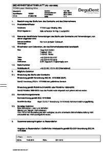
large number of stitches and in general: tasks where the planning of robot paths heavily rely on 3D models and advanced task sequencing and path planning algorithms [4]. RLW robot programming is a typical example where, besides the great programming effort required by the relatively large number of stitches, the on-line teaching is not even possible, due to the applied welding tool which is a laser beam. Therefore OLP is a key enabler in RLW robot programming.
Figure 1: The steps of off-line programming according to [5]. Note that the concept is based on the 3D model.
However, even though OLP in the virtual environment allows simulation and can help decrease the debugging time required for programming, OLP itself does not resolve totally the problem of time consumption. Large scale or complex tasks still demand excessive programming expenditure, which makes OLP suitable only for large volumes of production [7] [8] and also decreases the flexibility of the workcell against changes in production [5]. In order to answer the above challenges recent works focus on developing and using automated OLP methods [7] [8] . According to the steps defined in Figure 1 the process of automated OLP starts from the extraction or creation of the 3D model of the workcell, along with that of the workpiece, and the definition of the tasks. This is followed by the trajectory and process planning and ends up with executing the postprocessed code. In order to reduce the time demand of robot programming, these steps have to be automated or at least they have to be supported by effective mixed-initiative planning and programming methods [9]. PROBLEM STATEMENT In this paper a workcell is defined as a closed environment where RLW operations are executed by a single welding robot on a single workpiece at a time. During the configuration of an RLW workcell, in order to meet the technological and financial requirements, the design and the operation planning of the workcell has to be carried out as a part of an integrated workflow. The results of this workflow provide the static and the dynamic representation of the workcell in form of the physical arrangement of the selected components and the description of the operation sequences (i.e. motion plan) of the robot. As a following step of the workflow, so as to support the physical realization of the workcell configuration, the motion plan of the welding robot has to be translated into the native programming language of the robot. For avoiding the usually large time consumption and error proneness of robot programming the application of automated robot program generation is reasonable. The focus of this research is to develop an automatic robot program generation module, which extends the capabilities of an existing RLW workcell configurator. This includes the definition of a representation which is able to capture the resulting motion plan and allows for its translation into the programming language of the robot.
THE WORKSTATION CONFIGURATION WORKFLOW AND ITS IMPLEMENTATION Earlier, so as to solve the RLW workstation configuration and planning problems an integrated workflow has been defined [10]. Main phases, decision points, information flow and feedbacks of the workflow are shown in Figure 2. The two main problems can clearly be identified in the workflow: workstation configuration addresses the problem of finding an appropriate internal arrangement of the workcell that makes possible performing the prescribed welding tasks, while operation planning and OLP determine the task sequence, path of the scanner head, motion plan of the robot as well as its executable program. Starting from the initial task definition the phases of accessibility analysis, task sequencing, path planning with collision avoidance and workpiece placement are carried out by using mixed-initiative problem solving. Along with the following steps of inverse kinematics and trajectory calculation as well as the generation of robot program, the workflow shows large similarity to the general structure of off-line robot programming depicted in Figure 1. However, a difference has to be noted, that task sequencing (i.e., the process planning in Figure 1) precedes the trajectory planning. As task sequencing and path planning are executed in the reference frame of the workpiece, they can be executed independently from the trajectory planning. The methods of task sequencing and path planning are detailed in [11] [12].
Figure 2: The integrated workflow for workstation configuration and planning.
The execution of the defined integrated workflow relies on the application of a representation which is able to capture both the structure and the operational behavior of the workcell and therefore ensure
the integrity of the workflow for the representation as well. The applied representation is a so called linkage model, which models the workcell as a collection of parameterized kinematic pairs stored in a relational database. Defining the connectivity and its type between and within the kinematic pairs forms a graph structure, where the edges are geometric transformations between frames, attached to the nodes of the graph (i.e., elements of a workcell or an industrial robot). By using various types of parametric transformations (i.e., rotational, translational, fixed) this representation enables capturing the structural and operational aspects of the workcell. In addition, storing the geometric transformations also allows for executing inverse kinematics calculations regarding the dynamic elements of the workcell. As it is described in detail in [10] the elements of the workflow, up to robot program generation, were implemented and these components were integrated into a graphic software toolbox written in the .NET C# programming language. Since the application of computer aided methods for planning workcell operation demands a unified structure for describing the operation sequences, methods for automated control code generation can be implemented, which relies on the unified representation as input. This in one hand eliminates the drawbacks of manual programming, while on the other hand also enables the integration of code generation into the process of workcell configuration, thus speeding up the complete workflow of workstation configuration. IMPLEMENTATION OF AUTOMATED CODE GENERATION In order to extend the implementation with the automated generation of the robot program a new program module has to be included. It is required that the OLP module has to be based on the same representation as the workflow, since the inverse kinematics and its corresponding trajectory, calculated in previous phases of the workflow (see Figure 3), are the basis for generating the robot program. To improve the compatibility (usability), the OLP module is required to be generic, thus reducing the dependency on a specific robot and its language. However this does not mean the development of a universal robot language post-processor, but rather the definition of an abstract representation, which stands above robot languages and enables it mapping to different robot languages by adding translation extensions to the OLP module. This need for a generic robot program representation, the OLP module is also required to account for the application specific aspects of RLW robot programming. An RLW robot usually has a redundant kinematic structure (because of the additional links of the scanner-head), therefore during the inverse kinematics calculation a decomposition of the robot arms is applied (further description of the method can be found in [13]). An industrial practice for this decomposition is calculating the movements for the mechanical part (containing the scanner head center point, SCP) and the optical part (containing the tool center point, TCP, i.e., the end of the laser beam) of the robot arm. Thus the resulting robot movements are the superpositions of the movements of the two (virtually decomposed) robot arms. To meet these requirements, during the implementation of the OLP module the following class structure was defined for representing the robot program. This serves as an intermediate interface between the operation sequences and the language specific robot program. The class hierarchy is shown in the listings below:
Program o Program variables o Program routines o Movement segments
Movement
Interpolation type
Laser usage
Position
Robot arm identifier (ID)
Speed
Routines
Synchronized movements
When implementing the above items in the corresponding classes, each item can be extended with methods capable of describing a given item in a specific programming language, which provides a possible basis for further extension with additional programming languages. However, the focus of this research, in its current stage, was only aimed at one specific programming language supplied with the robot of the case study. The whole robot program is represented by an instance of the Program class, which serves as a container for all the variables, routines and movement segments. Variables and routines are only implementing wrapper classes, while a movement segment denotes a part of the trajectory as a sequence of consecutive movements. The movement segments are also designed to represent the arm decomposition applied during calculation of the inverse kinematics. In a movement segment two sequences of consecutive movements can be stored, describing the simultaneous trajectory of both arms. During the operation of the robot, the synchronized execution of the two movement sequences combines the virtually decomposed robot arms. The sequence of movements are built up by movement elements, which are the smallest elements of the trajectory (e.g. making a welding stitch). A movement defines the position of the destination, the ID of the robot arm corresponding to the decomposition, and the speed of the tool along the movement, the type of the applied interpolation, as well as the activity of the laser beam. The described class structure was implemented into a software module by using the C# .NET programming language, which was integrated into the previously developed Workstation Configuration and Planner application. Figure 3 shows a picture showing the graphic user interface of the application, with the results of the code generation module displayed.
Figure 3: A screen-capture showing the off-line programming module of the workstation configurator and planner application.
VALIDATION AND CASE STUDY For testing the robot program generation module, it was applied in a physical demonstrator case study, where a workcell using RSW is to be upgraded to RLW. This involves the complete walk-through of the workflow ending with the robot program generation and execution of the robot of the demonstrator cell (the previous steps are detailed in [10]). The robot used in the demonstrator case was a COMAU SMARTLASER C5, a 7 degrees of freedom (DoF) RLW robot. The robot’s native programming language is called PDL2. The model of the workcell is shown in Figure 4.
Figure 4: The workcell, which is the subject of the case-study containing the RLW robot, the workpiece, the fixture and the path of the scanner head.
Before executing the generated program by the robot it has to be syntactically checked, which can be done by using the WINC5G textual robot code editor environment supplied by the manufacturer of the robot. However, this only serves as a syntax check. In order to validate the results before uploading the code to the controller a parser tool has been developed which is able to read and interpret the generated robot program. The parser tool was developed by using ANTLR language recognition [14] tool embedded in a C# .NET application. For easy visualization the robot motions extracted from the reparsed code were visualized by using Wolfram’s Mathematica [15]. CONCLUSIONS In the paper the problem of RLW workstation configuration and planning was described and – for solving these two interrelated tasks – an integrated workflow was introduced. Implementing the elements of the workflow and integrating them into a software toolbox were carried out by defining and using a common task representation that also serves as a basis for the automated translation of the operation sequences into instructions written in the native programming language of an industrial robot. The defined workflow and the implemented software toolbox were put in use in a physical demonstrator case study. During the case study the software toolbox was used to execute the phases of the workflow and provide the results required for the OLP module. The calculated robot path and the corresponding inverse kinematics and trajectory were translated into the developed representation that allowed the generation of a robot program in the specific robot language used by the robot in the case study. The execution of the generated program delivered the expected results. The resulting robot program was validated syntactically by applying a code-development tool provided by the robot manufacturer and it was reparsed by a custom-tailored language interpreter as well. The validation succeeded in both cases. Regarding the future works, in order to improve the solution, they have to be aimed at performing further tests and case studies, as for the complete workflow and for the OLP module alone as well. Further developments of the OLP module can be focused on supporting additional programming languages as it would provide compatibility to a wider range of welding robots and thus allowing and inducing further developments for an even more generic implementation of the workflow and the OLP module. ACKNOWLEDGEMENTS This work has been supported by the EU FP7 grant RLW Navigator No. 285051, and the NFU grant ED-13-2-2013-0002. REFERENCES [1] G. Reinhart, U. Munzert and W. Vogl, "A programming system for robot-based remote-laserwelding with conventional optics," CIRP Annals, vol. 57, pp. 37-40, 2008. [2] G. Tsoukantas, K. Salonitis, A. Stournaras, P. Stavropoulos and G. Chryssoulouris, "On optical design limitations of generalized two-mirror remote beam delivery laser systems: the case of remote welding," International Journal of Advanced Manufacturing Technology, vol. 32, pp. 932-941, 2007.
[3] M. Zäh, J. Moesl, J. Musiol and F. Oefele, "Material processing with remote technology, revolution or evolution?," Physics Procedia 2010, vol. 5, pp. 19-33, 2010. [4] S. F. Chan and R. Kwan, "Post-processing methodologies for off-line robot programming within computer integrated manufacture," Journal of Materials Processing Technology, vol. 139, no. 1-3, pp. 8-14, 2003. [5] Z. Pan, J. Polden, N. Larkin, S. van Duin and J. Norrish, "Recent progress on programming methods for industrial robots," Robotics and Computer-Integrated Manufacturing, vol. 28, pp. 87-94, 2012. [6] P. Neto and N. Mendes, "Direct off-line robot programming via a common CAD package," Robotics and Autonomous Systems, vol. 61, no. 8, pp. 896-910, 2013. [7] A. Ames, E. Hinman-Sweeney and J. Sizemore, "Automated generation of weld path trajectories," The 6th IEEE International Symposium on Assembly and Task Planning: From Nano to Macro Assembly and Manufacturing, pp. 182-187, 2005. [8] M. Bruccoleri, C. D'Onofrio and U. L. Commare, "Off-line programming and simulation for automatic robot control software generation," 5th IEEE International Conference on Industrial Informatics, pp. 491-496, 2007. [9] C. Kohrt, R. Stamp, A. G. Pipe, J. Kiely and G. Schiedermeier, "An online robot trajectory planning and programming support system for industrial use," Robotics and ComputerIntegrated Manufacturing, vol. 29, no. 1, pp. 71-79, 2013. [10] G. Erdős, C. Kardos, Z. Kemény, A. Kovács and J. Váncza, "Workstation configuration and process planning for RLW operations," Procedia CRIP, vol. 17, pp. 783-788, 2014. [11] A. Kovács, „Collision-free path planning for remote laser welding,” Proc. of the 2nd ICAPS Workshop on Planning and Robotics (PlanRob2014), pp. 172-181, 2014. [12] A. Kovács, „Task Sequencing for Remote Laser Welding in the Automotive Industry,” Proc. of the 23rd International Conference on Automated Planning and Scheduling (ICAPS 2013), pp. 457-461, 2013. [13] G. Erdős, Z. Kemény, A. Kovács and J. Váncza, "Planning of remote laser welding processes," Procedia CIRP 2013, vol. 7, pp. 222-227, 2013. [14] T. Parr, The Definitive ANTLR 4 Reference, Dallas, Texas: The Pragmatic Programmers, LLC, 2012. [15] Wolfram Research, "Mathematica," 2014. [Online]. Available: http://www.wolfram.com/mathematica/. [Accessed 30 June 2014].