AREA COVERAGE STUDIES FOR AN AUTONOMOUS DEMINING ROBOT Jos´e Prado, Gonc¸alo Cabrita and Lino Marques Abstract— This work presents the autonomous area coverage with a lightweight mobile robot equipped with a mine detecting sensor head attached to the end-effector of a two degrees of freedom (2 DOF) actuator arm. Two coverage techniques were employed in this work, line-sweeping (LS) and spacial cell diffusion (SCD). The problem of improving the motion of the platform and the arm, in terms of: number of maneuvers, traversed distance, percentage of area covered and time was addressed. The feasibility and effectiveness of both algorithms are demonstrated by simulation results for coverage work of target area.
I. I NTRODUCTION Humanitarian demining is a risky task which usually leads to several victims among the deminers. Therefore, significant efforts are being made by the scientific community, in order to develop systems able to automatically detect landmines [1], keeping the users as safe as possible. Blast antipersonnel mines include less than 100 g of explosive and very little metal. Resorting to simple construction techniques these can be very cheap (around one US dollar) and as a consequence are extremely widespread. Due to the typical diameter of about 10 cm when digged or surrounded by grass they are very difficult to see. Blast mines are triggered by a ground pressure of about 10 kg/dm2 , these mines are not designed to kill but to badly maim [2]. Although mines are usually located close to the surface and present small amounts of metal, a mine field usually contains countless harmless metal objects of different sizes on a multitude of depths which contribute to the high false alarm rate. This work is a part of the ongoing project TIRAMISU (ISR, Coimbra, Portugal) aimed to develop demining technologies; among robots, sensors and devices that endows the exploration of a certain area and the location of landmines. In order to develop a system for landmine detection, some key measurable features, that characterizes the landmine, shall be properly selected. This issue is not a trivial task due to the fact that there is a large variety of antipersonnel landmines which differ from each other J. Prado, G. Cabrita and L. Marques are with the Department of Electrical and Computer Engineering, Institute of Systems and Robotics, University of Coimbra, 3030-290 Coimbra, Portugal.
{jaugusto, goncabrita, lino}@isr.uc.pt
Fig. 1.
Robot equipped with dual-sensor in the mobile arm.
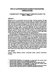
Fig. 2. Sample of anti-personal landmines with different shapes.
in its used materials, shape and size (see Figure 2 taken with permission from [3]). Different approaches has been proposed for the autonomous mine detection [4], [1]; the used sensors vary among metal-detectors, ground penetration radars, cameras, chemical sensors and others, or even the fusion of some of these sensors. However, the fact that the robot can only sense the mine when it is really close to it is a constraint present in all the scenarios. If the purpose of the robot is to map and not trigger the mines, this constraint affects the possible coverage strategies. Henceforth, in this paper a comparison between two coverage methods is made, taking into account the defined assessments and the current robotic platform 1, in order to reduce the cost/energy and time of the coverage task for the entire designated area. II. R ELATED W ORK Covering large areas is a task that is obviously useful in a large number of applications such as cleaning large surfaces, mapping purposes [5], and autonomous mine clearance [6]. While in indoor environments, the obstacles are
Fig. 3. Multi-sensor detection process after a combined robot and arm sweeping.
usually walls, furniture and structure of the building, in outdoor environments there can be trees, rocks, ravines; in either case an obstacle free environment is very rare. More specifically, for the demining task, the mines by itself shall be considered a special type of obstacle, that after detection, shall be mapped and avoided. There are several approaches for coverage in the literature, a line-sweep-based approach is described in [7], a spatial cell diffusion approach is presented in [8], in [9] a multi-robot coverage algorithm is presented, a smooth spiral path planning is studied in [10], an olfactory coordinated area coverage approach is described in [11]. When combining the movement of the platform with the movement of the arm, different approaches will certainly lead to different energy consumptions. Thus it is necessary to analyze which approach requires less energy, without losing the certainty of performing a complete area coverage. III. ROBOTIC ARM SWEEPING In order to detect and localize anti-personnel landmines with our dual-sensor equipped robot, a common approach is to cover all the area of a grid structured area. Due to the configuration of our robot, it was defined several cells with dimensions 1m x 1m each, those can be easily covered by the arm sweep, in front of the robot. Since each coil of the metal detector is equipped with one chemical sensor, the swiping movement of the arm generates simultaneously 3 lines of dual data. These dual sensor data is fused and interpolated based on the method proposed at [12]. Although an arm movement of 180 degrees would maximise the coverage area in front of the robot, the arm maximum angle also affects the maximum velocity of the robot. Thus we set the maximum angle of arm sweeping as 90 degrees, 45◦ to the left and 45◦ to the right. The sweeping speed recommended
by the manufacture of our metal detector is 0.25 m/s. Since our robotic arm has 1 m of extension, the distance of one arc sweep is π2 m. The covered strip, while √the robot moves forward, has a detection width of 2 m. Therefore we setup the arm speed at 0.25 m/s and the robot forward (scan speed) at 1 30 m/s. The rotation speed of the robot when stopped for maneuvers was defined as the maximum rotation speed, since no scan is desired during this type of maneuver. The fusion with interpolation enhances the generated map, providing thus a dense map of the region in front of the robot, instead of sparse lines. Samples of the output of the interpolated fused data are shown in the right column of figure 3. This speed configuration guarantees the covered movement represented in the top left corner of figure 3, endowing a dense map of the arc region in front of the robot. The probability of mine presence varies between 0 and 1 (i.e. 0% to 100%), therefore high peaks of probability are added to the navigation costmap [13] as being obstacles. Therefore, navigation continues the coverage algorithm while mapping and avoiding the discovered mines. IV. C OVERAGE First of all, let’s make some assumptions about important elements that describe a coverage problem: • The coverage region: The region to be covered is continuous and smooth (or can be embedded in the plane), is connected, and is defined by an outer perimeter and some mines (obstacles) in its interior. In this paper we will assume that perimeter is polygonal, and the mines are spread randomly. • The robot: It has nonholonomic constraints, it is a differential skid steer robot, and the shape of the robot is unrelated to the sensor/actuator pattern. The starting or ending position of the robot may be specified. • The sensors: The sensor or actuator has a one or two dimensional coverage pattern which sweeps out a two dimensional area as the robot moves. However the sensor moves, it is assumed that the generated sensor/actuator pattern does not move relative to the robot. The sensor pattern is larger than the robot. This is necessary because during the coverage of a mined field it is necessary that the robot moves towards a “clean” subregion, and it must fit in this subregion. • The robot can navigate outside the target area in order to maneuver, thus the map is always at least one cell larger in every direction than the target area. • A coverage algorithm must return: The coverage path through a detailed sequence of motion
to the configuration of our robot, let’s model C(T ), the energy cost function for the covered area as: Z T
C(T ) = α 0
(a) Line-sweep trajectory Fig. 4.
(b) SCD trajectory
Target trajectories for both algorithms.
commands for the robot. A. Line-Sweeping The line-sweeping algorithm works in two stages. In the first stage, the algorithm selects the longest edge of the field to determine the optimal direction of the sweep. In the second stage, it generates n tracks parallel to the field edges from the inside to be used as rows. For a given rectangular area of size m × n, where m ≥ n and w is the width of the sensor detection area. The number of lines is defined as n/w. The coverage algorithm than sends to the navigation cartesian coordinates of the points of turn, defining the optimal trajectory as represented in figure 4(a). Since we are considering that the testing area is strongly connected, a mine field with sparse and randomly distributed mines, this trajectory is achieved without the need of further area segmentation. B. Spatial Cell Diffusion The SCD algorithm moves the robot in a spiral movement, alternating clock-wise and counter-clockwise movements each time robot get stuck or reaches to a border of the target area. This algorithm performed well for areas with dense obstacles and low connectivity, as rooms and indoor environments [8]. According to the direction of search selected, robot navigates and sweeps the target region in consistent manner. While executing a coverage operation, the robot changes its direction of motion and reverses the sense of rotation at a boundary region of work space model. Alike in the line-sweep, the coverage SCD algorithm than sends the coordinates to the navigation planner, as represented in figure 4(b). V. M ETHODOLOGY A. Energy Since batteries are a limited resource, and energy sources are often not abundant near mined field areas, an important factor in field robotic coverage is to optimize the energy consumption of the robot. Due
|ω(t)| dt +β
Z T
|v(t)| dt +γ
0
Z T 0
|s(t)| dt (1)
where: • ω(t) is the velocity of rotation performed by the robot’s body, •
v(t) is the linear velocity of the robot,
•
s(t) is the arm rotation speed,
•
α is the rotation consumption, in W.h/◦ ,
•
β is the linear consumption, in W.h/m.
•
γ is the consumption of the arm sweeping in W.h/◦ .
Energy consumption of the robot was measured in different situations inserting a current and voltage monitor between the robot’s battery and its electric loads. Thus, the constants of the cost function are: α = 154, 68 W.h/◦ (average for robot rotation), β = 25, 78W.h/m (average of forward movement at scan speed), and γ = 3, 86W.h/◦ . Since these are consumption constants, different coverage algorithms varies in terms of number of maneuvers, traversed distance and total time, which directly influences the parameters R R |vel|dt and |ω|dt. Therefore, these parameters were measured, in a simulated environment. B. Simulated Environment A virtual 2D world created in Stage simulator was used as the simulated environment. The robot footprint has the dimensions of the Husky robot presented in figure 1, the 2D top view size of the robot is 0.81 m X 0.67 m. The arm dimensions were also designed accordingly, 1 m arm length and the arm sweeping angle was limited to 90 degrees. The navigation commands issued to this simulated robot are the same velocity commands issued for the real robot. Since in the real robot we plan to use GPS RTK and a very accurate localization is expected, in the simulator perfect odometry is been used as the localization reference. The sensor fusion technique presented on [12] results on a probability map of mine presence along the scanned area. Thus, in order to simulate the sensors, high peaks of probability of mine presence were injected on the scanned area when mines are found in that area of the map. This configuration combined with the coverage techniques allows representation of the detection map when coverage is complete.
(a) Line Sweep
(b) SCD Fig. 5.
Results of simulation in stage.
Henceforth, 3 mines were randomly positioned in a 10 m × 10 m maneuver space. Moreover, since the robot needs to be able to maneuver outside the target area, a 9m×9m inscribed sub-area was defined as the target area to be covered. The position of the mines can be seen (as small black points) together with the robot and sensor trail, the target area is marked by a dashed line, see figures 5(b) and 5(a). C. Assessments As the objective is to improve the motion of the platform together with its jointed arm, several assessments variables were defined for the metrics. The two analyzed coverage algorithms were compared in terms of: • •
•
•
• •
(c) Mine Probability Map
Energy: Energy consumption of the robot for the entire covered area. Number of maneuvers: the forward linear motion is more efficient in terms of energy consumption, thus the maneuvers shall be reduced. Traversed distance: the total time of coverage is desired to be low, however since the total time is relative to the speed of the robot, we normalized the time by the speed and decided to use the total traversed distance as a metric. Percentage of overlapping: the percentage of area that is covered more than one time. In a ideal case, the robot establishes a path that does not need to repeat any cell or any subarea of the target area. However, in most cases this is not possible due to the obstacles and specially because in the demining task the robots does not know a priori where are the mines. Percentage of area covered: the percentage of area covered is required to be 100%. Mine detection rate: the quality of the generated map will be better analyzed when field tests are realized, however for now we are using this metric to know if the robot detected all the mines or if it missed some of them.
VI. E XPERIMENTS In order to evaluate the robot’s behavior during each of the analyzed coverage algorithms, the Stage simulator was used. Stage provides a virtual world populated by mobile robots and sensors, along with various objects for the robots to sense and possibly manipulate. Each algorithm was executed 10 times in the simulation space, with mines distributed randomly changing position and amount of mines. The amount of mines varied between 1 and 5 mines and the space and shape of the target area was kept constant as 9 m × 9 m inscribed in a 10 m × 10 m maneuver space. The defined assessments were measured and annotated, with special attention to the energy consumption. The size of the simulated landmines was also kept constant for all tests. The simulated landmines size was based on the mean size of the probability peak generated by the detection method proposed in [12] when scanning the M114 (also known as MAPS), an old Portuguese made anti-personal blast mine. Samples of the robot and sensor trail for both algorithms, in one map configuration, can be seen in figure 5. VII. R ESULTS AND DISCUSSION The results presented in table I are the mean of the 10 times performed simulation per each of the algorithms. Notice that in the number of maneuvers the amount right of the plus sign indicates small maneuvers that the robot performed in order to avoid stepping on the mines, while the number at left of the plus sign are about the maneuvers to keep the coverage path. The mine detection rate was 100% for both cases since none of the current tests presented a false-negative (a miss-detection). An example of one probability map of mine presence is presented in figure 5(c). The traversed distance was very similar at both algorithms, in the current tests this is acceptable because of the sparsely distributed mines. In future work we plan to investigate the behavior of these
algorithms with a dense set of mines among subareas of the field. TABLE I P ERFORMANCE COMPARISON BETWEEN THE TESTED COVERAGE ALGORITHMS .
Energy C(x) Number of maneuvers Mine detection rate Traversed distance Percentage of overlapping Percentage of covered area
Line-Sweep 22W.h 17+3 100% 80,1m 30% 100%
SCD 23W.h 25+3 100% 82,3m 27% 100%
VIII. C ONCLUSIONS This paper addresses the problem of optimising the energy consumption for a coverage task done with a demining robot equipped with a 2DOF scanning arm. In such setup, the end-effector motion results from the motion of the platform or the arm, or both. A cost function for these possible end-effector movements was defined and used to evaluate the global cost of covering a given area with different coverage algorithms. This paper describes ongoing works in this area. In the final version, a deeper study of the global cost influence of different coverage algorithms for different types of environments will be provided. ACKNOWLEDGEMENTS This work was partially carried-out in the framework of TIRAMISU project (www.fp7-tiramisu.eu). This project is funded by the European Community’s Seventh Framework Program (FP7) under grant 284747.
R EFERENCES [1] M. Y. Rachkov, L. Marques, and A. T. de Almeida, “Multisensor demining robot,” Autonomous robots, vol. 18, no. 3, pp. 275–291, 2005.
[2] P. M¨achler, “Detection technologies for anti-personnel mines,” in Proceedings of the Autonomous Vehicles in Mine Countermeasures Symposium, 1995, pp. 6–150. [3] D. of National Defence of Canada, “Canadian forces mine database,” available on DVD request only, 2009. [4] S. Larionova, L. Marques, and A. de Almeida, “Toward practical implementation of sensor fusion for a demining robot,” in IEEE/RSJ Int. Conf. on Intelligent Robots and Systems, 2004. [5] H. Choset, “Coverage for robotics–a survey of recent results,” Annals of mathematics and artificial intelligence, vol. 31, no. 1-4, pp. 113–126, 2001. [6] P. Gonzalez de Santos, J. A. Cobano, E. Garcia, J. Estremera, and M. Armada, “A six-legged robot-based system for humanitarian demining missions,” Mechatronics, vol. 17, no. 8, pp. 417–430, 2007. [7] W. H. Huang, “Optimal line-sweep-based decompositions for coverage algorithms,” in Robotics and Automation, 2001. Proceedings 2001 ICRA. IEEE International Conference on, vol. 1. IEEE, 2001, pp. 27–32. [8] S.-W. Ryu, Y.-h. Lee, T.-Y. Kuc, S.-H. Ji, and Y.-S. Moon, “A search and coverage algorithm for mobile robot,” in Ubiquitous Robots and Ambient Intelligence (URAI), 2011 8th International Conference on. IEEE, 2011, pp. 815–821. [9] E. Gonzalez and E. Gerlein, “BSA-CM: A multi-robot coverage algorithm,” in Web Intelligence and Intelligent Agent Technologies, 2009. WI-IAT’09. IEEE/WIC/ACM International Joint Conferences on, vol. 2. IET, 2009, pp. 383–386. [10] T.-K. Lee, S.-H. Baek, S.-Y. Oh, and Y.-H. Choi, “Complete coverage algorithm based on linked smooth spiral paths for mobile robots,” in Control Automation Robotics & Vision (ICARCV), 2010 11th International Conference on. IEEE, 2010, pp. 609–614. [11] S. Larionova, N. Almeida, L. Marques, and A. de Almeida, “Olfactory coordinated area coverage,” Autonomous Robots, vol. 20, no. 3, pp. 251–260, 2006. [12] J. Prado, G. Cabrita, and L. Marques, “Bayesian sensor fusion for land-mine detection using a dual-sensor handheld device,” in IECON 2013, the 39th Annual Conference of the IEEE Industrial Electronics Society, 2013. [13] M. Quigley, K. Conley, B. Gerkey, J. Faust, T. Foote, J. Leibs, R. Wheeler, and A. Y. Ng, “ROS: an open-source robot operating system,” in ICRA workshop on open source software, vol. 3, no. 2, 2009.