Cambridge University Press 978-1-107-02494-6 - Networked Life: 20 Questions and Answers Mung Chiang Excerpt More information
1
What makes CDMA work for my smartphone?
1.1
A Short Answer Take a look at your iPhone, Android phone, or a smartphone running on some other operating system. It embodies a remarkable story of technology innovations. The rise of wireless networks, the Internet, and the web over the last five decades, coupled with advances in chip design, touchscreen material, battery packaging, software systems, business models... led to this amazing device you are holding in your hand. It symbolizes our age of networked life. These phones have become the mobile, lightweight, smart centers of focus in our lives. They are used not just for voice calls, but also for data applications: texting, emailing, browsing the web, streaming videos, downloading books, uploading photos, playing games, or video-conferencing friends. The throughputs of these applications are measured in bits per second (bps). These data fly through a cellular network and the Internet. The cellular network in turn consists of the radio air-interface and the core network. We focus on the air-interface part in this chapter, and turn to the cellular core network in Chapter 19. Terrestrial wireless communication started back in the 1940s, and cellular networks have gone through generations of evolution since the 1970s, moving into what we hear as 4G these days. Back in the 1980s, some estimated that there would be 1 million cellular users in the USA by 2000. That turned out to be one of those way-off under-estimates that did not even get close to the actual impact of networking technologies. Over more than three decades of evolution, a fundamental concept of cellular architecture has remained essentially the same. The entire space of deployment is divided into smaller regions called cells, which are often represented by hexagons as in Figure 1.1, thus the name cellular networks and cell phones. There is one base station (BS) in each cell, connected on the one side to switches in the core network, and on the other side to the mobile stations (MSs) assigned to this cell. An MS could be a smart phone, a tablet, a laptop with a dongle, or any device with antennas that can transmit and receive in the right frequencies following a cellular network standard. There are a few other names for them, for example, sometimes an MS is also called a User Equipment (UE) and a BS called a Node B (NB) or an evolved Node B (eNB).
© in this web service Cambridge University Press
www.cambridge.org
Cambridge University Press 978-1-107-02494-6 - Networked Life: 20 Questions and Answers Mung Chiang Excerpt More information
2
What makes CDMA work for my smartphone?
3
4 1 MSA
MS
2
B
7
6
BS
5
BS
3
2
BS
4 1
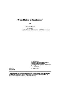
Figure 1.1 Part of a typical cellular network with a frequency reuse of 7. Each cell is a
hexagon with a base station (BS) and multiple mobile stations (MSs). Only a few of them are drawn in the figure. Each BS has three directional antennas, each of which covers a 120-degree sector. Some mobile stations, like MS A, are close to the base station with strong channels to the BS. Others, like MS B, are on the cell edge with weak channels. Attenuation enables frequency reuse, but the variability of and the inability to control attenuation pose challenges to wireless cellular network design.
We see a clear hierarchy, a fixed infrastructure, and one-hop radio links in cellular networks. This is in contrast to other types of wireless networks. Moreover, the deployment of base stations is based on careful radio engineering and tightly controlled by a wireless provider, in contrast to WiFi networks in Chapter 18. Why do we divide the space into smaller regions? Because the wireless spectrum is scarce and radio signals weaken over space. Transmitting signals over the air means emitting energy over different parts of the electromagnetic spectrum. Certain regions of the spectrum are allocated by different countries to cellular communications, just like other parts of the spectrum are allocated to AM and FM radio. For example, the 900 MHz range is allocated for the most popular 2G standard called GSM, and in Europe the 1.95 GHz range and 2.15 GHz range are allocated for UMTS, a version of the 3G standard. Some part of the spectrum is unlicensed, like in WiFi, as we will see in Chapter 18. Other parts are licensed, like those for cellular networks, and a wireless service provider needs to purchase these limited resources with hefty prices. The spectrum for cellular networks is further divided into chunks, since it is often easier for transmitters and receivers to work with narrower frequency bands, e.g., on the order of 10 MHz in 3G. The signals sent in the air become weaker as they travel over longer distances. The amount of this attenuation is often proportional to the square, or even the fourth power, of the distance traversed. So, in a typical cellular network, the signals become too weak to be accurately detected after a couple of miles. At
© in this web service Cambridge University Press
www.cambridge.org
Cambridge University Press 978-1-107-02494-6 - Networked Life: 20 Questions and Answers Mung Chiang Excerpt More information
1.1 A Short Answer
f
f
f
t (a)
3
t (b)
t (c)
Figure 1.2 Part of a time–frequency grid is shown in each graph. For visual clarity, we
only show two slices of resources being used. (a) FDMA and (b) TDMA are dedicated resource allocation: each frequency band or timeslot is given to a user. In contrast, (c) CDMA is shared resource allocation: each time–frequency bin is shared by multiple users, all transmitting and receiving over the same frequency band and at the same time. These users are differentiated by signal processing. Power control also helps differentiate their signals.
first glance, this may sound like bad news. But it also means that the frequency band used by base station A can be reused by another base station B sufficiently far away from A. All we need to do is tessellate the frequency bands, as illustrated in Figure 1.1, so that no two cells share the same frequency band if they are too close. In Figure 1.1, we say that there is a frequency reuse factor of 7, since we need that many frequency bands in order to avoid having two close cells sharing the same frequency band. Cellular architecture enables the network to scale up over space. We will visit several other ways to scale up a network later. Now, how can the users in the same cell share the same frequency band? There are two main approaches: orthogonal and non-orthogonal allocation of resources. Frequency is clearly one type of resource, and time is another. In orthogonal allocation, each user is given a small band of frequency in FrequencyDivision Multiple Access (FDMA), or a timeslot in Time-Division Multiple Access (TDMA). Each user’s allocation is distinct from others, as shown in Figure 1.2(a) and (b). This often leads to an inefficient use of resources. We will see in later chapters a recurring theme: a dedicated assignment of resources to users becomes inefficient when users come and go frequently. The alternative, non-orthogonal allocation, allows all users to transmit at the same time over the same frequency band, as in Code-Division Multiple Access. CDMA went through many ups and downs with technology adoption from 1989 to 1995, but is now found in all the 3G cellular standards as part of the design. In CDMA’s first standard, IS-95 in the 2G family, the same frequency band is reused in all the cells, as illustrated in Figure 1.2(c). But how can we distinguish the users if their signals overlap with each other? Think of a cocktail party with many pairs of people trying to carry out individual conversations. If each pair takes turns in communicating, and only one
© in this web service Cambridge University Press
www.cambridge.org
Cambridge University Press 978-1-107-02494-6 - Networked Life: 20 Questions and Answers Mung Chiang Excerpt More information
4
What makes CDMA work for my smartphone? person gets to talk during each timeslot, we have a TDMA system. If all pairs can communicate at the same time, and each uses a different language to avoid confusion, we have a CDMA system. But there are not enough languages whose pronunciations do not cause confusion, and human ears are not that good at decoding, so interference is still an issue. How about controlling each person’s volume? Each transmitter adjusts the volume of its voice according to the relative distances among the speakers and listeners. In a real cocktail party, unless there is some politeness protocol or it hurts people’s vocal chord to raise their voice, we end up in a situation where everyone is shouting and yet most people cannot hear well. Transmit power control should mitigate this problem. The core idea behind the CDMA standards follows our intuition about the cocktail party. First, the transmitter multiplies the digital signals by a sequence of 1s and minus 1s, a sequence we call the spreading code. The receiver multiplies the received bits by the same spreading code to recover the original signals. This is straightforward to see: 1×1 is 1, and −1×−1 is also 1. What is non-trivial is that a family of spreading codes can be designed such that only one spreading code, the original one used by the transmitter, can recover the signals. If you use any other spreading code in this family, you will get noise-like, meaningless bits. We call this a family of orthogonal codes. Users are still separated by orthogonalization, just along the “code dimension” as opposed to the more intuitive “time dimension” and “frequency dimension.” This procedure is called direct sequence spread spectrum, one of the standard ways to enable CDMA. However, there may not be enough orthogonal spreading codes for all the mobile stations. Families of orthogonal codes are limited in their sizes. Furthermore, a slight shift on the time axis can scramble the recovered bits at the receiver. We need the clocks on all the devices to be synchronized. But this is infeasible for the uplink, where mobiles talk to the base station: MSs cannot easily coordinate their clocks. It is difficult even in the downlink, where the base station talks to the mobiles: the BS has a single clock but the wireless channel distorts the bits. Either way, we do not have perfectly orthogonal spreading codes, even though these imperfect codes still provide significant “coding gain” in differentiating the signals. We need an alternative mechanism to differentiate the users and to tackle the interference problem. Wireless signals are just energy propagating in the air, and one user’s signal is every other user’s interference. Interference, together with the attenuation of signals over distance and the fading of signals along multiple paths, are the the top three issues we have to address in wireless channels. Interference is an example of negative externality that we will encounter many times in this book, together with ways to “internalize” it by designing the right mechanism. Here is an example of significant interference. As shown in Figure 1.1, a user standing right next to the BS can easily overwhelm another user far away at the edge of the cell. This is the classic near-far problem in CDMA networks. It
© in this web service Cambridge University Press
www.cambridge.org
Cambridge University Press 978-1-107-02494-6 - Networked Life: 20 Questions and Answers Mung Chiang Excerpt More information
1.1 A Short Answer
5
was solved in the IS-95 standard by Qualcomm in 1989. This solution has been one of the cornerstones in realizing the potential of CDMA since then. Qualcomm’s solution to the near-far problem is simple and effective. The receiver infers the channel quality and sends that back to the transmitter as feedback. Consider an uplink transmission: multiple MSs trying to send signals to the BS in a particular cell. The BS can estimate the channel quality from each MS to itself, e.g., by looking at the ratio of the received signal power to the transmitted power, the latter being pre-configured to some value during the channel-estimation timeslot. Then, the BS inverts the channel quality and sends that value, on some feedback control channel, back to the MSs, telling them that these are the gain parameters they should use in setting their transmit powers. In this way, all the received signal strengths will be made equal. This is the basic MS transmit power control algorithm in CDMA. But what if equalization of the received signal powers is not the right goal? For voice calls, the typical application on cell phones in 2G networks in the 1990s, there is often a target value of the received signal quality that each call needs to achieve. This signal quality factor is called the Signal to Interference Ratio (SIR). It is the ratio between the received signal strength and the sum strength of all the interference (plus the receiver noise strength). Of course, it is easy to raise the SIR for just one user: just increase its transmitter’s power. But that translates into higher interference for everyone else, which further leads to higher transmit powers being used by them if they also want to maintain or improve their SIRs. This positive feedback escalates into a transmit power “arms race” until each user is transmitting at the maximum power. That would not be a desirable state to operate in. If each user fixes a reasonable target SIR, can we do better than this “arms race” through a more intelligent power control? Here, “being reasonable” means that the SIRs targeted by all the users in a cell are mutually compatible; they can be simultaneously achieved by some configuration of transmit powers at the MSs. The answer is yes. In 1992-1993, a sequence of research results developed the basic version of Distributed Power Control (DPC), a fully distributed algorithm. We will discuss later what we mean by “distributed” and “fully distributed.” For now, it suffices to say that, in DPC, each pair of transmitter (e.g., an MS) and receiver (e.g., the BS) does not need to know the transmit power or channel quality of any other pair. At each timeslot, all it needs to know is the actual SIR it currently achieves at the receiver. Then, by taking the ratio between the fixed, target SIR and the variable, actual SIR value measured for this timeslot, and multiplying the current transmit power by that ratio, we get the transmit power for the next timeslot. This update happens simultaneously at each pair of transmitter and receiver. This simple method is an iterative algorithm; the updates continue from one timeslot to the next, unlike with the one-shot, received-power-equalization algorithm. But it is still simple, and when the target SIRs can be simultaneously achieved, it has been proven to converge: the iterative procedure will stop over
© in this web service Cambridge University Press
www.cambridge.org
Cambridge University Press 978-1-107-02494-6 - Networked Life: 20 Questions and Answers Mung Chiang Excerpt More information
6
What makes CDMA work for my smartphone? time. When it stops, it stops at the right solution: a power-minimal configuration of transmit powers that achieves the target SIRs for all. DPC converges quite fast, approaching the right power levels with an error that decays as a geometric series. DPC can even be carried out asynchronously: each radio has a different clock and therefore different definitions of what timeslot it is now. Of course, in real systems the timeslots are indeed asynchronous and power levels are discrete. Asynchronous and quantized versions of DPC have been implemented in all the CDMA standards in 3G networks. Some standards run power control 1500 times every second, while others run 800 times a second. Some discretize power levels to 0.1 dB, while others between 0.2 and 0.5 dB. Without CDMA, our cellular networks today could not work as efficiently. Without power control algorithms (and the associated handoff method to support user mobility), CDMA could not function properly. In Chapter 19, we will discuss a 4G standard called LTE. It uses a technology called OFDM instead of CDMA, but power control is still employed for interference reduction and for energy management. Later, in Chapter 18, we will discuss some of the latest ideas that help further push the data rates in new wireless network standards, ranging from splitting, shrinking, and adjusting the cells to overlaying small cells on top of large ones for traffic offloading, and from leveraging multiple antennas and tilting their positions to “chopping up” the frequency bands for more efficient signal processing.
1.2
A Long Answer
1.2.1
Distributed power control Before we proceed to a general discussion of the Distributed Power Control (DPC) algorithm, we must first define some symbols. Consider N pairs of transmitters and receivers. Each pair forms a (logical) link, indexed by i. The transmit power of the transmitter of link i is pi , some positive number, usually capped at a maximum value: pi ≤ pmax (although we will not consider the effect of this cap in the analysis of the algorithm). The transmitted power impacts both the received power at the intended receiver and the received interference at the receivers of all other pairs. Now, consider the channel from the transmitter of link (i.e., transmitter– receiver pair) j to the receiver of link i, and denote the channel gain by Gij . So Gii is the direct channel gain; the bigger the better, since it is the channel for the intended transmission for the transmitter–receiver pair of link i. All the other {Gij }, for j not equal to i, are gains for interference channels, so the smaller the better. We call these channel “gains”, but actually they are less than 1, so maybe a better term is channel “loss.” This notation is visualized in Figure 1.3 for a simple case of two MSs talking to a BS, which can be thought of as two different (logically separated) receivers physically located together.
© in this web service Cambridge University Press
www.cambridge.org
Cambridge University Press 978-1-107-02494-6 - Networked Life: 20 Questions and Answers Mung Chiang Excerpt More information
1.2 A Long Answer Transmitter 1
7
Receiver 1 G11 G21
G12 G22 Transmitter 2
Receiver 2
Figure 1.3 Uplink interference between two mobile stations at the base station. We
can think of the base station as two (logically separated) receivers collocated. G11 and G22 are direct channel gains, the bigger the better. G12 and G21 are interference channel gains, the smaller the better.
Each Gij is determined by two main factors: (1) location of the transmitter and receiver and (2) the quality of the channel in between. Gii is also enhanced by the CDMA spreading codes that help the intended receivers decode more accurately. The received power of the intended transmission at the receiver is therefore Gii pi . What about the interference? It is the sum of Gij pj over all transmitters j P (other than the intended one i): j6=i Gij pj . There is also noise ni in the receiver electronics for each receiver i. So we can write the SIR, a unit-less ratio, at the receiver of logical link i as Gii pi . j6=i Gij pj + ni
SIRi = P
(1.1)
For proper decoding of the packets, the receiver needs to maintain a target level of SIR. We will denote that as γi for link i, and we want SIRi ≥ γi for all i. Clearly, increasing p1 raises the SIR for receiver 1 but lowers the SIR for all other receivers. As in a typical algorithm we will encounter throughout this book, we assume that time is divided into discrete slots, each indexed by [t]. At each timeslot t, the receiver on link i can measure the received SIR readily, and feeds back that number, SIRi [t], to the transmitter. The DPC algorithm can be described through a simple equation: each transmitter simply multiplies the current power level pi [t] by the ratio between the target SIR, γi , and the current measured SIRi [t], to obtain the power level to use in the next timeslot: pi [t + 1] =
γi pi [t], for each i. SIRi [t]
(1.2)
We will use the symbols ∀i later to say “for each i.”
© in this web service Cambridge University Press
www.cambridge.org
Cambridge University Press 978-1-107-02494-6 - Networked Life: 20 Questions and Answers Mung Chiang Excerpt More information
8
What makes CDMA work for my smartphone? We see that each receiver i needs to measure only its own SIR at each iteration, and each transmitter only needs to remember its own target SIR. There is no need for passing any control message around, like telling other users what power level it is using. Simple in communication, it is a very distributed algorithm, and we will later encounter many types of distributed algorithms in various kinds of networks. This algorithm is also simple in its computation: just one division and one multiplication. And it is simple in its parameter configuration: there are actually no parameters in the algorithm that need to be tuned, unlike in quite a few other algorithms in later chapters. Simplicity in communication, computation, and configuration is a key reason why certain algorithms are widely adopted in practice. Intuitively, this algorithm makes sense. First, when the iterations stop because no one’s power is changing any more, i.e., when we have convergence to an equilibrium, we can see that SIRi = γi for all i. Second, there is hope that the algorithm will actually converge, given the direction in which the power levels are moving. The transmit power moves up when the received SIR is below the target, and moves down when it is above the target. Proving that convergence will happen is not as easy. As one transmitter changes its power, the other transmitters are doing the same, and it is unclear what the next timeslot’s SIR values will be. In fact, this algorithm does not converge if too many γi are too large, i.e., when too many users request large SIRs as their targets. Third, if satisfying the target SIRs is the only criterion, there are many transmit power configurations that can do that. If p1 = p2 = 1 mW achieves these two users’ target SIRs, p1 = p2 = 10 mW will do so too. We would like to pick the configuration that uses the least amount of power; we want a power-minimal solution. And the algorithm above seems to be lowering the power when a high power is unnecessary. DPC illustrates a recurring theme in this book. We will see in almost every chapter that individual’s behaviors driven by self-interest can often aggregate into a fair and efficient state globally across all users, especially when there are proper feedback signals. In contrast, either a centralized control or purely random individual actions would have imposed significant downsides.
1.2.2
DPC as an optimization solution In general, “will it converge?” and “will it converge to the right solution?” are the top two questions that we would like to address in the design of all iterative algorithms. Of course, what “the right solution” means will depend on the definition of optimality. In this case, power-minimal transmit powers that achieve the target SIRs for all users are the “right solution.” Power minimization is the objective and achieving target SIRs for all users is the constraint.
© in this web service Cambridge University Press
www.cambridge.org
Cambridge University Press 978-1-107-02494-6 - Networked Life: 20 Questions and Answers Mung Chiang Excerpt More information
1.2 A Long Answer
9
SIR2
Pareto Optimal
SIR1
Figure 1.4 An illustration of the SIR feasibility region. It is a constraint set for power
control optimization, and visualizes the competition among users. Every point strictly inside the shaded region is a feasible vector of target SIRs. Every point outside is infeasible. And every point on the boundary of the curve is Pareto optimal: you cannot increase one user’s SIR without reducing another user’s SIR.
In this case, there are many ways to address these questions, for example, using machineries from optimization theory or game theory. Either way, we can show that, under the condition that the target SIR values are indeed achievable at all (i.e., there are some values of the transmit powers that can achieve the target SIRs for all users), DPC will converge, and converge to the right solution. We can illustrate a typical set of feasible SIRs in the SIR feasibility region shown in Figure 1.4. Clearly, we want to operate on the boundary of this region, and each point on the boundary is called Pareto optimal. Along this boundary, one user’s higher SIR can be achieved, but at the expense of a lower SIR for another user. This highlights another recurrent theme in this book: the need to tackle tradeoffs among competing users and across different design objectives, and the importance of providing incentives for people to react to. There is no free lunch; and we have to balance the benefits with the costs. It turns out that DPC also solves a global optimization problem for the network. Here, “global” means that the interests of all the users are incorporated. In this case, it is the sum of transmit powers that is minimized, and every user’s target SIR must be met. Once we have an objective function and a set of constraints, and we have defined which quantities are variables and which are constants, an optimization problem is formulated. In this case, the transmit powers are the variables. The achieved SIRs are also variables, but are derived from the powers. All the other quantities are the constants: they are not degrees of freedom under your control. If the variable vector x0 satisfies all the constraints, it is called a feasible solution. If an optimization problem’s constraints are not mutually compatible, it is called infeasible. If an x∗ is both feasible and better than any other feasible
© in this web service Cambridge University Press
www.cambridge.org
Cambridge University Press 978-1-107-02494-6 - Networked Life: 20 Questions and Answers Mung Chiang Excerpt More information
10
What makes CDMA work for my smartphone? solution, i.e., gives the smallest objective function value for a minimization problem (or the largest objective function value for a maximization problem), it is called an optimal solution. An optimal solution might not exist, e.g., minimize 1/x for x ∈ R. And optimal solutions may not be unique either. Here is the optimization problem of varying transmit power to satisfy fixed target SIR constraints and then minimize the total power: P minimize i pi (1.3) subject to SIRi (p) ≥ γi , ∀i variables p. Problem (1.3) looks complicated if we substitute the definition (1.1) of the SIR as a function of the whole vector p: P minimize i pi subject to P GGiiijppi j +ni ≥ γi , ∀i variables
j6=i
p.
But it can be simplified through a different representation. We can easily rewrite it as a linear programming problem: minimizing a linear function of the variables subject to linear constraints of the variables: P minimize i pi P subject to Gii pi − γi ( j6=i Gij pj + ni ) ≥ 0, ∀i variables p. Linear programming problems are easy optimization problems. More generally, convex optimization (to be introduced in Chapter 4) is easy; easy in theory in terms of complexity and easy in practice with fast solution software. In the Advanced Material, we will derive DPC as the solution to problem (1.3). We will be formulating and solving optimization problems many times in future chapters. Generally, solving a global optimization via local actions by each user requires explicit signaling. But in this case, it turns out that the selfish behavior of users in their own power minimization also solves the global, constrained optimization problem; their interests are correctly aligned already. This is more of an exception than the norm.
1.2.3
DPC as a game Power control is a competition. One user’s received power is another’s interference. Each player searches for the right “move” (or, in this case, the right transmit power) so that its “payoff” is optimized (in this case, the transmit power is the smallest possible while providing the user with its target SIR γi ). We also hope that the whole network reaches some desirable equilibrium as each player strategizes. The concepts of “players,” “move,” “payoff,” and “equilibrium” can be defined in a precise and useful way.
© in this web service Cambridge University Press
www.cambridge.org