Double Pulse Switching Board
Double Pulse Switching Board
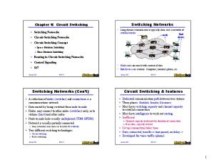
GA100SBJT12-FR4 VDS, MAX ID, MAX
Features
Compatible
1200 V, 100 A Testing Low Series Inductance Design Wide, 6 oz. Copper Current Traces Multiple DUT and FWD Connections for Durability Low Resistance and Inductance Gate Drive Connection
= =
1200 V 100 A
SiC Junction Transistors (SJT) SiC MOSFETS Silicon Power MOSFETs Fast Silicon IGBTs
Electrical Characteristics Parameter Test Voltage Maximum Drain Current Maximum Capacitor Bank Parasitic Inductance Maximum Stored Energy
Symbol VDS, MAX ID, MAX Cbank Ls Emax
Conditions
VDS = 800 V, ID = 6 A VDS = 1200 V
Value 1200 100 5.0 60 3.6
Unit V A µF nH J
Notes
Overview The GeneSiC Double Pulse Test Board is designed for performing switching tests on a wide variety of silicon and SiC power transistors. It is designed using low ESL capacitors and PCB traces to have a low parasitic series inductance (LS) current path. This allows recorded data to be most representative of the device under test (DUT) and minimize testing circuit distortions. The board is capable of up to 1200 V and 100 A. User-provided external load inductor, DUT, and free-wheeling diode (FWD) may be soldered directly to the board, without testing sockets, for the lowest possible contact resistance and inductance. A gate drive circuit board may be mounted directly on to the Test Board for a short, low inductance path to the DUT gate pin connection.
Figure 1: Double Pulse Test Board
Figure 2: GeneSiC Semiconductor Switching Test Board Schematic
Sept. 2015
http://www.genesicsemi.com/commercial-sic/sic-junction-transistors/
Pg 1 of 5
Double Pulse Switching Board
GA100SBJT12-FR4
MHV Voltage Conn.
Voltage Balancing
5 µF Capacitor Bank
Drain Current Sensor Conn.
+ External Load Inductor Connection
FWD
Gate Drive Conn.
– DUT
Figure 3: Switching Test Board with Labeling
MHV Voltage Connection High voltage for testing up to 1200 V is supplied to the Test Board through a MHV coaxial connection. Voltage may be generated through a high voltage power supply.
Capacitor Bank The capacitor bank is comprised of 20, 1 µF, 630 V capacitors to store up to 3.6 J of energy to supply to the DUT. The bank includes 10 low effective series inductance (ESL) surface mount ceramic capacitors to allow DUT drain currents to rise and fall with minimal circuit interference. Copper traces of 6 oz. thickness on the Test Board also minimize parasitic inductance.
Voltage Balancing Network A voltage balancing network of two 1 MΩ, 2 W SMD resistors is used to ensure an equal potential is across the series connected capacitors on the Test Board along with two blocking rectifiers to protect against extreme overvoltage of the energy storage capacitors.
External Load Inductor A load inductor (not provided) can be soldered directed to the HV and Drain nodes on their provided connection pads. Care should be taken to ensure the voltage rating of the inductor is not exceeded. Also, if the chosen inductor value is too large the capacitor bank may discharge before the inductor is fully charged to the desired test current ID level during double pulse testing. An inductance of Lload ≤ 1.0 mH is suggested.
Device Under Test (DUT) and Free Wheeling Diode (FWD) The DUT and FWD should be soldered into the connection terminals with minimal extra lead length. Leads extending through the Test Board should be trimmed from the package to reduce electrical noise which may distort measurement during ultra-fast, high-voltage switching. Devices may be connected to isolated hotplates while connected to the Test Board for high-temperature testing as desired. It is also recommended to probe any device voltages (i.e. VGS, VDS) as close as possible to the device for accurate measurement and minimal testing induced voltage and current ringing.
Sept. 2015
http://www.genesicsemi.com/commercial-sic/sic-junction-transistors/
Pg 2 of 5
Double Pulse Switching Board
GA100SBJT12-FR4
Drain Current Sensor Connection A low inductance measurement of the DUT drain current can be made utilizing the drain current sensor connection along with the use of a Pearson Electronics Current Monitor (shape “F”, not provided). The connection can best be made utilizing a wide metallic conductor extending from the GND node partially encasing the current monitor with a wide conductor extending through the current monitor eye-hole and connecting to the source node beneath. These two nodes, source and GND, must be connected for the Test Board to operate properly and when used in this configuration the drain current passed through a current monitor for data recording while adding minimal parasitic inductance. If the drain current is not being sensed at the Drain Current Sensor Connection the two nodes must be shorted together using a wide jumper cable.
Figure 4: Drain Current Sensor Connection with Pearson Current Monitor installed using a low inductance current path.
Gate Drive Connection The Gate Drive Connection may be used to connect a gate drive board to the Test Board and DUT. It is designed to receive the gate drive board voltage inputs from an external supply as well as the digital gate control signal and pass them through the Test Board to the gate drive board inputs through a 6 pin, in-line header connection. The output gate connection of the gate drive board is directly fed into the Test Board gate node through a 3 pin header and is passed with a low parasitic inductance connection to the DUT gate pin along with a similar source connection return. The use of the Gate Drive Connection is optional and DUT gate driving is fully customizable to the users’ specifications and preferences. The connection of any gate drive topology may be made to the Gate Drive Connection or directly to the DUT.
Figure 5: GeneSiC Gate Drive Board (GA03IDDJT30-FR4) connected to the Test Board’s Gate Drive Connection
Sept. 2015
http://www.genesicsemi.com/commercial-sic/sic-junction-transistors/
Pg 3 of 5
Double Pulse Switching Board
GA100SBJT12-FR4
Example Capability Switching Waveforms
Figure 6: SJT 800V Switching Turn On Waveform
#ITEM 1 2
Designator C1, C2, C3, C4, C5, C6, C7, C8, C9, C10 C11, C12, C13, C14, C15, C16, C17, C18, C19, C20
Figure 7: SJT 800V Switching Turn Off Waveform
Table 1: Bill of Materials Package Manufacturer (Metric) Capacitor, Film, 1µF, 630V, Through Hole Kemet Radial
Description
Capacitor, Ceramic, 1µF, 630V, X7T, SMD Resistor, 1 MΩ, 2W, 1%, 2512, SMD Silicon Diode, Ultra Fast, 1.2 kV, 5A, Connector, BNC MHV Jack Connector, Header 0.100IN, Female, 6POS, Vertical Connector, Header 0.100IN, Female, 3POS, Vertical Terminal Block, 6POS, Side Entry, 5.08 mm Connector, BNC Jack, 50 Ω
Manufacturer Part Number
Quantity / Board
R75PR4100AA30K
10
Stacked SMD
TDK Corp
CKG57NX7T2J105M500JH 10
6432
TE Connectivity
2-2176071-2
TO-220
STMicroelectronics STTH512D
2
Through Hole
Amphenol
000-27000
1
Through Hole
Sullins Connector
PPTC061LFBN-RC
1
Through Hole
Sullins Connector
PPTC031LFBN-RC
2
Through Hole
TE Connectivity
282837-6
1
Through Hole
TE Connectivity
5-1634503-1
1
3
R1, R2
4
D6, D7
5
U1
6
U2
7
GATE, SOURCE
8
U3
9
U4
10
DUT
Device Under Test
Not Provided
1
11
FWD
Free Wheeling Diode
Not Provided
1
12
U5
Drain Current Sensor
Not Provided
1
13
IL
Load Inductor
Not Provided
1
Sept. 2015
Pearson Shape “F”
http://www.genesicsemi.com/commercial-sic/sic-junction-transistors/
2
Pg 4 of 5
Double Pulse Switching Board
GA100SBJT12-FR4
Revision History Date
Revision
Comments
2015/09/11
2
Updated Characteristics
2015/03/20
1
Updated Characteristics
2014/09/15
0
Initial release
Supersedes
Published by GeneSiC Semiconductor, Inc. 43670 Trade Center Place Suite 155 Dulles, VA 20166 GeneSiC Semiconductor, Inc. reserves right to make changes to the product specifications and data in this document without notice. GeneSiC disclaims all and any warranty and liability arising out of use or application of any product. No license, express or implied to any intellectual property rights is granted by this document. Unless otherwise expressly indicated, GeneSiC products are not designed, tested or authorized for use in life-saving, medical, aircraft navigation, communication, air traffic control and weapons systems, nor in applications where their failure may result in death, personal injury and/or property damage.
Sept. 2015
http://www.genesicsemi.com/commercial-sic/sic-junction-transistors/
Pg 5 of 5