Acta Electrotechnica et Informatica No. 1, Vol. 7, 2007
1
DIRECT TORQUE CONTROL STRATEGY OF INDUCTION MOTORS *
Riad TOUFOUTI, Salima MEZIANE, Hocine BENALLA *
Department of Electrical Engineering, University Mentouri , aîn el bey Road Constantine Algeria, tel. +213319113, E-mail:
[email protected]
SUMMARY Direct Torque Control of inverter-fed Induction Machine allows high dynamic performance by means of very simple control schemes. In this paper various direct torque control methodologies as conventional DTC (C_DTC), modified DTC (M_DTC) and twelve sectors (12_DTC) have been analysed and compared in order to evaluate the influence of the motor operating condition on steady state performances. A particular emphasis on stator flux trajectory, torque ripple and stator current distortion has been made. Simulation results show the effectiveness of the proposed methods.
Keywords: induction motor, direct torque control, three phase inverter, look-up table.
1. INDRODUCTION Advanced control of electrical machines requires an independent control of magnetic flux and torque. For that reason it was not surprising, that the DCmachine played an important role in the early days of high performance electrical drive systems, since the magnetic flux and torque are easily controlled by the stator and rotor current, respectively. The introduction of Field Oriented Control [1] meant a huge turn in the field of electrical drives, since with this type of control the robust induction machine can be controlled with a high performance. Later in the eighties a new control method for induction machines was introduced: The Direct Torque Control (DTC) method is characterised by its simple implementation and a fast dynamic response. Furthermore, the inverter is directly controlled by the algorithm, i.e. a modulation technique for the inverter is not needed. However if the control is implemented on a digital system (which can be considered as a standard nowadays); the actual values of flux and torque could cross their boundaries too far [2] [3], which is based on an independent hysteresis control of flux and torque. The main advantages of DTC are absence of coordinate transformation and current regulator absence of separate voltage modulation block. Common disadvantages of conventional DTC are a sluggish response (slow response) in both starts up and changes in either flux or torque, large and small errors in flux and torque are not distinguished. In other words, the same vectors are used during start up and step changes and during steady state. In order to overcome the mentioned drawbacks, there are different solutions, which can be classified as follows modification of the switching table, so modified DTC (M_DTC) and twelve sectors DTC (12_DTC). In this paper a comparison of various direct torque control methodologies (Conventional TC, M-DTC, and 12_DTC) have been presented with evaluation of the influence on the transient performances of induction motor.
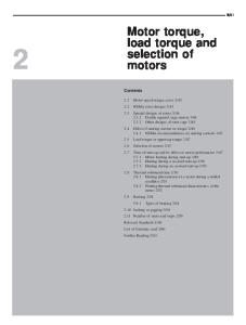
2. DIRECT TORQUE CONTROL WITH THREE-LEVEL INVERTER The basic functional blocks used to implement the DTC scheme are represented in Figure.1. The instantaneous values of the stator flux and torque are calculated from stator variable by using a closed loop estimator [1]. Stator flux and torque can be controlled directly and independently by properly selecting the inverter switching configuration.
Fig. 1 Basic direct torque control scheme for AC motor drives
3. VECTOR MODEL OF INVERTER OUTPUT VOLTAGE In a voltage fed three phases, the switching commands of each inverter leg are complementary. So for each leg a logic state Ci (i=a,b,c) can be defined. Ci is 1 if the upper switch is commanded to be closed and 0 if the lower one in commanded to be close (first).
ISSN 1335-8243 © 2007 Faculty of Electrical Engineering and Informatics, Technical University of Košice, Slovak Republic
2
Direct Torque Control Strategy of Induction Motors
The stator resistance can be assumed constant during a large number of converter switching periods Te. The voltage vector applied to the induction motor remains also constant during one period Te. The stator flux is estimated by integrating the difference between the input voltage and the voltage drop across the stator resistance as given by equations (4): Fig. 2 Three phase voltage inverter t
ϕS =
Since three are 3 independent legs there will be eight different states, so 8 different voltages. Applying the vector transformation described as:
Vs =
2π 4π j j 2 ⎡ U 0 ⎢C1 + C 2 e 3 + C3e 3 3 ⎢ ⎣
⎤ ⎥ ⎥⎦
(1)
As it can be seen in second, there are six nonzero voltage vectors and two zero voltage vectors which correspond to (C1, C2, C3)= (111)/ (000) as shown by Figure.3 [1][3].
S
− RS I
S
During the switching interval, each voltage vector is constant and (4) is then rewritten as in (5):
ϕ S (t ) ≈ ϕ S 0 + Vs Te
(5)
In equation; φs0 stands for the initial stator flux condition. In fact, we have d ϕ S ≈ V s . The following dt Fig.4 is established for the case Vs=V3.
2 4
Component of Torque
VS=V3
V2(FI,TI)
V1 1
ϕs ωs0+Δωs1
2 V3(FD,TI) 4
5
t=Te
q
1
(4)
) dt
0
V2
V3
V4
∫ (V
γ0+Δγ
3 V6(FI,TD) V5(FD,TD)
6
ϕr
ωs0 ϕso
t=0
γ0 ϕro
V6 V5
θro
Component of flux
θso
Fig. 3 Partition of the d, q plane into six sectors
d
Fig. 4 An example for flux deviation 3.1. Stator flux control Stator voltage components (Vsd,Vsq) on perpendicular (d,q) axis are determined from measured values (Uo and Isabc). Boolean switching controls (C1,C2 ,C3,) by, [1][2]: ⎧ 2 1 ⎛ ⎞ U 0 ⎜ C1 − (C 2 + C 3 ) ⎟ ⎪V Sd = ⎪ 3 2 ⎝ ⎠ ⎨ ⎪V = 1 U (C − C ) 0 2 3 ⎪⎩ Sq 2
(2)
And stator current components (Isd,Isq) : ⎧ ⎪ I Sd = ⎪ ⎨ ⎪I = ⎪⎩ Sq
2 Isa 3 1 2
(Isb
(3) − Isc
)
Neglecting the stator resistance, (5) implies that the end of the stator flux vector will move in the direction of the applied voltage vector, as shown in Figure.4. ϕso is the initial stator flux linkage at the instant of switching. To select the voltage vectors for controlling the amplitude of the stator flux linkage, the voltage vector plane is divided into six regions, as shown in Figure.3. In each region, two adjacent voltage vectors, which give the minimum switching frequency, are selected to increase or decrease the amplitude of stator flux , respectively. For instance, the vectors V4 and V3 are selected for to increase or to decrease the amplitude of stator flux when it is in region number 1. In this way, can be controlled at the required value by selecting the proper voltage vectors. The voltage vectors are selected for keeping the magnitud stator flux and electromagnetic torque within a hysteresis band [3][7].
ISSN 1335-8243 © 2007 Faculty of Electrical Engineering and Informatics, Technical University of Košice, Slovak Republic
Acta Electrotechnica et Informatica No. 1, Vol. 7, 2007
3
3.2. Stator flux and torque estimation
V2
V3
V2(FI,TI)
The magnitude of stator flux, which can be estimated by (6).
⎧ ⎪ϕ ⎪ ⎨ ⎪ϕ ⎪ ⎩
V4(FD,TI) 5
t
Sd
=
∫ (V
Sd
− RS I
Sd
V4
) dt
0
(6)
3
1
4
6
t
Sq
=
∫ (V
Sq
− RS I
Sq
7
2
6
V1
5
) dt
0
V6 V5
The stator flux linkage phasor is given by
Fig. 5 Modified DTC and its new six sectors
ϕS = ϕ2Sd + ϕ2Sq
(7)
By comparing the sign of the components stator flux (ϕsd ϕsq) and the amplitude of stator flux, we can localize the zone where we find the flux. Electromagnetic torque calculation uses flux components (6), current components (3) and P, pairpole number of the induction machine [2][8]:
(
Γem = p ϕ sd I sq − ϕ sq I sd
)
(8)
In accordance with the Figs (3)-(5) the general Tab.1 can be written.
V1 V2 V3 V4
As shown in Fig.3, eight switching combinations can be selected in a voltage source inverter, two of which determine zero voltage vectors and the others generate six equally spaced voltage vectors having the same amplitude. According to the principle of operation of DTC, the selection of a voltage vector is made to maintain the torque and stator flux within the limits of two hysteresis bands. The switching selection table for stator flux vector lying in the first sector of the d-q plane is given in Tab.1[1][2]. Sector Torque ΔΓ=1 Δϕ=1 ΔΓ=0 ΔΓ=-1 ΔΓ=1 Δϕ=0 ΔΓ=0 ΔΓ=-1
V1(FI,TD)
V5(FD,TD)
1
2
3
4
5
6
V2 V7 V6 V3 V0 V5
V3 V0 V1 V4 V7 V6
V4 V7 V2 V5 V0 V1
V5 V0 V3 V6 V7 V2
V6 V7 V4 V1 V0 V3
V1 V0 V5 V2 V7 V4
Flux
Tab. 1 Switching table for Conventional DTC
4. IMPROVEMENT OF THE SWITCHING TABLE
V5 V6
CLASSICAL DTC -30°→30° 30°→-30° Torque ambiguity 90°→30° TI, FI 150°→90° TI, FI -150°→150° Torque ambiguity -90°→-150° TD, FD -30°→-90° TD, FI
MODIFIED DTC 0°→60° 0°→-60° TD, FI 60°→0° TI, FI 120°→60° Flux ambiguity 180°→120° TI, FD -120°→-180° TD, FD -60°→-120° Flux ambiguity
Tab. 2 Behaviour of each state just in the first zone for the Conventional DTC (C_DTC) and the modified DTC (M_DTC).TI/ID: Torque increase/decease.FI/FD: Flux increase/Decrease It can be seen that the states V1 and V4, are not used in the Conventional DTC (C_DTC). The raison of this; is that they can increase or decrease the torque at the same sector depending on if the position is in its first 30 degrees or in its second ones. In the modified DTC (M_DTC), the vectors V3 and V6 are not used. However, now the reason is the ambiguity in flux instead of torque, as it was in the C_DTC. This considered being an advantage in favour of the M_DTC as the main point it to control the torque. Therefore, it is better to loose the usage of two for flux ambiguity that for torque one [5][6]. Tab.(1)-(3) show the Conventional DTC and the modified DTC look up table for all its six sectors. Sector Torque ΔΓ=1 Δϕ=1 ΔΓ=0 ΔΓ=-1 ΔΓ=1 Δϕ=1 ΔΓ=0 ΔΓ=-1
1
2
3
4
5
6
V2 V7 V1 V4 V7 V5
V3 V0 V2 V5 V0 V6
V4 V7 V3 V6 V7 V1
V5 V0 V4 V1 V0 V2
V6 V7 V5 V2 V7 V3
V1 V0 V6 V3 V0 V4
Flux
While being inspired by the zone shift strategy, the idea is to improve the DTC by a change of the operation table and to modify the six zones of the Conventional DTC (Tab.1) [1], as instead of taking the first sector of.-30° to 30°, it is taken of 0° to 60° one gets the new operation table of the modified DTC (Tab.2), [3][5]. The positions of the zones for the two strategies are shown by the Fig.5 [7][ 8].
Tab. 3 The switching table for Modified DTC
4
Direct Torque Control Strategy of Induction Motors
5. DTC TWELVE SECTOR TABLE (DTC_12) In Conventional DTC there are two states per sector that present a torque ambiguity. Therefore, they are never used. In a similar way, in the modified DTC there are two states per sector that introduce flux ambiguity, so they are never used either. It seems a good idea that if the stator flux locus is divided into twelve sectors instead of just six, all six active states will be used per sector. Consequently, it is arisen the idea of the twelve sector modified DTC (DTC12). This novel stator flux locus is introduced in Fig.6 [6].
9 4
8
3
6
V4
1V4(FD,TsI)
2
5
V5(FD,TD) 1
1
V1
12
7 8
V5
V4(FD,TsD)
11 9
V3(FD,TI)
1
V5(FD,TD)
FD
TsI
TsD
TD
TI
TsI
TsD
TD
S1
V2
*V2
V1
V6
V3
V4
V7
V5
S2
V3
V2
*V1
V1
V4
*V4
V5
V6
S3
V3
*V3
V2
V1
V4
V5
V0
V6
S4
V4
V3
*V2
V2
V5
*V5
V6
V1
S5
V4
*V4
V3
V2
V5
V6
V7
V1
S6
V5
V4
*V3
V3
V6
*V6
V1
V2
S7
V5
*V5
V4
V3
V6
V1
V0
V2
S8
V6
V5
*V4
V4
V1
*V1
V2
V3
V1(FI,TsD)
S9
V6
*V6
V5
V4
V1
V2
V7
V3
V6(FI,TD)
S10
V1
V6
*V5
V5
V2
*V2
V3
V4
V2(FI,TI)
S11
V1
*V1
V6
V5
V2
V3
V0
V4
V1(FI,TsI)
S12
V2
V1
*V6
V6
V3
*V3
V4
V5
V6(FI,TD)
V6
Fig. 6 Twelve sector modified DTC (12_DTC) and its sectors.FD/FI: flux decrease/increase. TD/TI: torque decrease/increase. TsD/TsI: torque small decrease/increase. Notice how all six voltage vectors can be used in all twelve sectors, disappearing all ambiguities. Tab.4 can be written when a twelve-sector locus is used. S12
F1 TI
V2(FI,TI)
V3(FD,TI)
φ τ
V2
V3
be measured. Therefore, the hysteresis block should have four hysteresis levels at is suggested in Tab.5 [1] [7] [6].
INCREASE
DECREASE
Stator Flux
V1, V2, V6
V3, V4, V5
Torque
V1, V2, V3
V4, V5, V6
S1
INCREASE
DECREASE
Stator Flux
V1, V2, V6
V3, V4, V5
Torque
V2, V3, V4
V5, V6, V1
Tab. 4 Table for sectors 12 and 1 in the 12_DTC. Notice how all six voltage vectors can be used in all sectors disappearing all ambiguities.
It has been mentioned in the previous paragraph, it is necessary to define small and large variations. It is obvious that V1 will produce a large increase in flux and a small increase in torque in sector S12. On the contrary, V2 will increase the torque in large proportion and the flux in a small one. It is reasonable to deduce that the torque error should be divided in the number of intervals that later on will
Tab. 5 Switching table for the 12_DTC. FD/FI: flux decrease/increase. TD/=/I: torque decrease/equal/increase. (* there is no suitable state. It has been chosen the second most suitable).
6. SIMULATION RESULTS Induction Machine Equations and data The Induction motor can be modelled with stator flux and rotor flux as the state variables by (9). ⎡dϕs ⎢ ⎢ dt ⎢ ⎢ ⎢ ⎢dϕr ⎢ ⎣ dt
⎤ ⎥ ⎥ ⎥ ⎥ ⎥ ⎥ ⎥ ⎦
=
1 ⎡ ⎢ − σ Ts ⎢ ⎢ ⎢ ⎢ ⎢ Lm ⎢⎣ σ Ts . Ls
Lm
⎤
⎡ϕ ⎤ σ Ts . Lr . ⎥⎥ ⎢ s ⎥
⎥ ⎥ ⎥ 1 ⎥ jω r − σ Tr ⎥⎦
⎢ ⎢ ⎢ ⎢ ⎢⎣ ϕ r
⎥ ⎥ ⎥ ⎥ ⎥⎦
+
⎡1 ⎤ ⎢ ⎥ ⎢ ⎥u ⎢ ⎥ ⎢ ⎥ ⎣0 ⎦
(9)
Where:
ϕs ,ϕ r
Stator and rotor flux vector Ts =Ls /Rs ,Tr=Lr/Rr :Stator and rotor time constant Rs, Rr, Stator and rotor résistance Ls, Lr, Stator and rotor self inductance Lm Mutual inductance σ=1-Lm2/LsLr Leakage coefficient ωr Rotor angular velocity
u
Stator voltage vector
Pn=3kW, Un=230V, Rs=2.89Ω, Rr=2.39Ω, Ls=Lr=0.225H, Lm=0.214H, P=2,
ISSN 1335-8243 © 2007 Faculty of Electrical Engineering and Informatics, Technical University of Košice, Slovak Republic
Acta Electrotechnica et Informatica No. 1, Vol. 7, 2007
5
ELECTROMAGNETIC TORQUE
STATORIC DIRECT and OPPOSITE FLUX
12
0.8 0.6
10
0.4
8 TORQUE[N.m]
Fqs [Wb]
0.2 0 -0.2
6
4
-0.4
2 -0.6 -0.8 -0.8
-0.6
-0.4
-0.2
0 Fsd[Wb]
0.2
0.4
0.6
0
0.8
0
0.05
0.1
0.15
0.2 TEMPS[s]
0.25
0.3
0.35
0.4
Fig. 9a Torque Response C_DTC
Fig. 8a The stator flux circle C_DTC
ELECTROMAGNETIC TORQUE
STATORIC DIRECT and OPPOSITE FLUX
12
0.8 0.6
10
0.4
8 TORQUE[N.m]
Fqs [Wb]
0.2 0 -0.2
6
4
-0.4
2 -0.6 -0.8 -0.8
-0.6
-0.4
-0.2
0 Fsd[Wb]
0.2
0.4
0.6
0
0.8
0
0.1
0.15
0.2 TEMPS[s]
0.25
0.3
0.35
0.4
Fig. 9b Torque Response M_DTC
Fig. 8b The stator flux circle M_DTC
ELECTROMAGNETIC TORQUE
STATORIC DIRECT and OPPOSITE FLUX 0.8
12
0.6
10
0.4
8 TORQUE[N.m]
0.2 Fqs [Wb]
0.05
0 -0.2
6
4
2
-0.4 0
-0.6 -0.8 -0.8
-0.6
-0.4
-0.2
0 Fsd[Wb]
0.2
0.4
0.6
Fig.8c The stator flux circle12_DTC Fig. 8c The stator flux circle 12_DTC
0.8
-2 0
0.05
0.1
0.15
0.2 TEMPS[s]
0.25
0.3
0.35
Fig. 9c Torque Response 12_DTC
0.4
6
Direct Torque Control Strategy of Induction Motors
STATOR CURRENT 15
10
5
Isa[A]
0
-5
-10
-15
-20
0
0.05
0.1
0.15
0.2 TEMPS[s]
0.25
0.3
0.35
0.4
0.35
0.4
Fig.10a The stator current C_DTC STATOR CURRENT 15
10
5
Isa[A]
0
-5
-10
-15
-20
0
0.05
0.1
0.15
0.2 TEMPS[s]
0.25
0.3
Fig.10b The stator current M_DTC STATOR CURRENT 25
Isa[A]
20
in Fig 8, 9 and 10 respectively. All three figure are the responses to step change torque command from zero to 10 N.m, which is applied at 0.0 sec. Fig.8 (a, b and c) Shows that the flux of the M_DTC and 12_DTC offers the fast transient responses That means the trajectory of stator flux established more quickly than that of the Conventional C_DTC. The simulation results show that the torque responses are very good dynamic response for four DTC methods, but the response of the torque conventional DTC presented of the ripple; By M_DTC and 12_DTC techniques shown Fig. 9(b and c ) the ripple of torque in steady state is reduced remarkably compared with conventional DTC, the torque changes through big oscillation and the torque ripple is bigger in conventional DTC shown Fig. 9a. Fig.9 (a, b, and c ) show the stator current in both control schemes. Even though both functions seem to be sinusoidal, it could be expected that the stator current in the Conventional DTC has more harmonic distortion because the effects caused by flux drooping is more evident. In the DTC induction drive, increased switching frequency is desirable since it reduces the harmonic content of the stator currents. However if high switching frequency is used, this will result in significantly increased switching losses (leading to reduced efficiency) and increased stress on the semiconductor devices of the inverter. From this study, we can conclude that the method of Modified DTC present the maid of performances. The reduction of oscillations of stator flux and torque response, in transient and steady state, is shown by Fig.8 (b), 9(b) and 10(b). Applying a zone shift angular (θ equal to (-0.4) degree, we can observe an optimal reduction of the flux nodulations, as shown in Fig.8 (b), Consequently, Consequently, as illustrated in Fig.10(b), the current have less harmonic distortion . It can be control performances are obtained without degradation, as shown in Fig.9 (b).
15
8. CONCLUSION
10
In this paper a comparison of various direct torque control methodologies (Conventional TC, MDTC, and 12_DTC) have been made in order to evaluate the influence of the motor operating condition on transient state performance. A particular emphasis on stator flux, torque ripple has been studied. The simulation results suggest that modification by conventional DTC of induction motor can achieve precise control of the stator flux and torque. Compared to conventional DTC, presented method can be easily implemented , and the steady performances of ripples of both torque and flux are considerably improved. The main improvements shown are: • Reduction of torque and current ripples in transient and steady state response. • No flux droppings caused by sector changes circular trajectory. • Fast stator flux response in transient state.
5 0 -5 -10 -15
0
0.05
0.1
0.15
0.2 0.25 TEMPS[s]
0.3
0.35
0.4
Fig. 10c The stator current 12_DTC 7. INTERPRETATION RESULTS
The results of simulation of Conventional DTC (C_DTC), modified DTC (M_DTC) and twelve sector DTC (12_DTC) of induction motor is shown
ISSN 1335-8243 © 2007 Faculty of Electrical Engineering and Informatics, Technical University of Košice, Slovak Republic
Acta Electrotechnica et Informatica No. 1, Vol. 7, 2007
7
REFERENCES
BIOGRAPHIES
[1] Takahashi, I. - Noguchi, T: A new quickresponse and high-efficiency control strategy of induction motor, IEEE Trans. On IA, Vol.22, N°.5, Sept/Oct 1986, PP.820-827. [2] Depenbrock, M: Direct self – control (DSC) of inverter – fed induction machine, IEEE Trans. Power Electronics, Vol.3, N°.4, Oct 1988, PP.420-829. [3] Casadei, D. - Profumo, F. - Serra,G. - Tani, A: FOC - DTC:Tox Viable Schemes for induction Motors Ttorque Control, IEEE Trans. Power Electronics. On PE, Vol.17, N°.5, Sept2002, [4] Casadei, D. - Serra, G: Implementation of direct Torque control Algorithme for Induction Motors Based On Discrete Space Vector Modulation, IEEE Trans. Power Electronics. Vol.15, N°.4, JULY2002, [5] A.A.Pujol, ″ Improvements in direct torque control of induction Motors″, Thèse de doctorat de L’UPC, Novembre2000 [6] Chapuis, Y. A : Contrôle direct du couple d’une machine asynchrone par l’orientation de son flux statorique, Thèse Doctorat INP, Grenoble 1996. [7] Toufouti, R. - Meziane, S. - Benalla. H : Amélioration Des Performances De La DTC De La Machine Asynchrone, Conférence Maghrébine en Génie Electrique 2004 CMGE04 12-13 avril 2004 à CONSTANTINE l'Antique CIRTA – Algérie. [8] Toufouti , R. - Benalla, H. - Meziane S :ThreeLevel Inverter With Direct Torque Control For Induction Motor, World Conference on Energy for Sustainable Development: Technology Advances and Environmental Issues,Pyramisa Hotel Cairo - Egypt, 6 - 9 December 2004
Toufouti Riad: was born in Constantine, Algeria, in 1974, in 1999 received the Engineer degree from the university of Montouri Constantine. Algeria. In 2003 received the M.S. degrees in electrical engineering, Option electrical machine. Associate teacher in Constantine University from October 1999 to 2003. In 2003 inscription in doctor's degree, permanent teacher from January 2004 in Souk ahras University, member for laboratory Of Electrical engineering university Constantine. Algeria Hocine Benalla: was born in Algeria in 1957. He received the D.E.A. and Doctor engineer degree in power electronics from the National Polytechnic Institute of Toulouse, France, in 1981 , and. 1984, respectively. In 1995, he received the Ph.D. degrees in electrical engineering from University of Jussieu -Paris 6, France. He is currently an Assistant Professor at University of Constantine Algeria. His current research interests include electric machines, ac drives and active filter.
Meziane Salima: was born in Oum El Bouaghi, Algeria, in 1974, in 2000 received the Engineer degree from the University of Montouri Constantine. Algeria. In 2003 received the M.S. degrees in electrical engineering, Option electrical machine. Associate teacher in Oum El Bouaghi University from October to 2003. In 2004 inscription in doctor's degree, permanent teacher from October 2004 in Souk ahras University, member for laboratory Of Electrical engineering university Constantine. Algeria.