Analog/Digital Conversion with Microcontrollers Document Revision: 1.01 Date: 17 April 2006
16301 Blue Ridge Road, Missouri City, Texas 77489 Telephone: 1-713-283-9970 Fax: 1-281-416-2806 E-mail:
[email protected] Web: www.bipom.com
This document is available for download from www.bipom.com © 2009 by BiPOM Electronics. All rights reserved. Analog/Digital Conversion with Microcontrollers. No part of this work may be reproduced in any manner without written permission of BiPOM Electronics. All trademarked names in this manual are the property of respective owners.
Overview Micro-controllers are useful to the extent that they communicate with other devices, such as sensors, motors, switches, keypads, displays, memory and even other micro-controllers. Many interface methods have been developed over the years to solve the complex problem of balancing circuit design criteria such as features, cost, size, weight, power consumption, reliability, availability, manufacturability. Many microcontroller designs typically mix multiple interfacing methods. In a very simplistic form, a microcontroller system can be viewed as a system that reads from (monitors) inputs, performs processing and writes to ( controls ) outputs. Input Devices
Microcontroller
Output Devices
Microcontroller Interfaces
Digital
On/Off
Analog
Parallel
Serial
Asynchronous
Voltage
Synchronous
1-wire
2-wire (I2C)
RS232/RS485
4-wire (SPI, Microwire)
Ethernet
Page
2
Current
Analog Inputs/Outputs Voltage-based control and monitoring. Disadvantages Advantages • • • •
Simple interface Low cost for low-resolutions High speed Low programming overhead
• • • •
High cost for higher resolutions Not all microcontrollers have analog inputs/outputs built-in Complicates the circuit design when external ADC or DAC are needed. Short distance, few feet maximum.
Voltage type: Typical ranges • • • • • •
0 to 2.5V 0 to 4V 0 to 5V +/- 2.5V +/- 4V +/- 5V
Current type: Typical ranges • •
0-20mA 4-20mA
Analog Interface Vcc
Amplifier Potentiometer
LM35 Temperature Sensor Vcc
Vcc
Analog/ Digital Converter (ADC)
8051 Microcontroller (AT89C51ED2)
Digital/ Analog Converter (DAC)
4-20mA Output
Strain-gage
Page
3
Sensor Types • • • • • • • • • • •
Temperature Humidity Light Acceleration Force Frequency Flow Pressure Torque Proximity Displacement
Page
4
Analog Digital Conversion • • • • •
Voltage to Frequency Flash ADC Successive Approximation Dual-Slope Integration Delta-Sigma
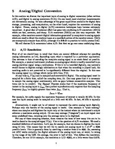
Successive approximation ADC Successive Approximation ADC’s are popular for use with microcontrollers due to low-cost and ease of interfacing. A successive approximation ADC consists of: • • • •
Successive Approximation Register Result Register DAC Comparator
Successive-approximation register counts by trying all values of bits starting with the mostsignificant bit and finishing at the least-significant bit. Throughout the count process, the register monitors the comparator's output to see if the binary count is less than or greater than the analog signal input, adjusting the bit values accordingly. This way, the DAC output eventually converges on the analog input signal and the result is presented in the Result register.
Page
5
Voltage
DAC Output Input Voltage
Time ADC can be external to the microcontroller or built-in:
Analog/Digital Converter (ADC)
Analog/ Digital Converter (ADC)
AT89C51ED2 Microcontroller
Page
6
PIC16F818 Microcontroller
Noise considerations Many sensors, such as thermocouples, generate a relatively small voltage so noise is always an issue. The most common source of noise is the utility power lines (50 Hz or 60 Hz). Typically, the bandwidth for temperature sensors is much lower than 50 or 60 Hz so a simple low-pass filter will work well in many cases. Other measures to keep noise away: •
Keep the sensor wires short.
•
Use shielded sensor cables with twisted pair wires.
•
Use a dedicated precision voltage reference, not the microcontroller supply.
•
Use 4-20mA loop or even better, a digital signal for long cable runs.
•
Provide low impedance paths to ground at the ADC inputs if possible.
•
Average readings in software.
•
Analog ground and digital ground should connect at the ADC.
•
Analog ground should not carry large currents.
•
Ground planes should not carry any currents.
Sensor
Analog/Digital Converter (ADC)
Analog Ground
Page
7
Digital Ground
Microcontroller
Semiconductor Temperature Sensors Analog Voltage Output Typically three-pin devices: Power, ground and output. INPUT
LM34: Fahrenheit sensor ( 10 millivolts/Fahrenheit ) LM35: Celsius sensor ( 10 millivolts/Celsius ) LM335: Kelvin sensor ( 10 millivolts/Kelvin ) Current Output
LM34, LM35 or LM335
GROUND
OUTPUT
GROUND
Typically 2-pin devices. AD590: Kelvin sensor ( 1uA/Kelvin )
Analog Temperature Sensor
Analog/Digital Converter (ADC)
Microcontroller
Digital Frequency Output MAX6576 1-wire DS18B20 2-wire/SMBUS
Digital Temperature Sensor
DS1621 3-wire DS1620
Page
8
Microcontroller
Analog/Digital Converter Application Examples
Digital Scale Voice Recorder Voice Recognition Sprinkler control system Engine controller Power Supply controller Factory automation Medical ( EEG, ECG, etc. ) Instrumentation – voltmeters, digital oscilloscopes, ohmmeters
Page
9