Development and Performances of a Dental Digital Radiographic System Using a High Resolution CCD Image Sensor Jong-Ho Kim, Su-Gil So and Koan-Sik Joo
Abstract--A dental digital radiographic (DDR) system using a high resolution charge-coupled device (CCD) imaging sensor was developed and the performances of this system for dental clinic imaging was evaluated. In order to determine the performances of the system, the modulation transfer function (MTF), the signal to noise ratio according to X-ray exposure, the dose reduction effects and imaging quality of the system were investigated. This system consists of a CCD imaging sensor (pixel size: 22 µm) to detect X-ray, an electrical signal processing circuit and a graphical user interface software to display the images and diagnosis. The MTF was obtained from a fourier transform of the line spread function (LSF), which was itself derived from the edge spread function (ESF) of a sharp edge image acquired. The spatial resolution of the system was measured at a 10% contrast in terms of the corresponding MTF value and the distance between the X-ray source and the CCD image sensor was fixed at 20 cm. The best image quality obtained at the exposure conditions of 60 kVp, 7 mA and 0.05 sec. At this time, the signal to noise ratio and X-ray dose were 23 and 41% (194 µGy) of a film-based method (468 µGy). The spatial resolution of this system, the result of MTF, was approximately 12 line pairs per mm at the 0.05 exposure time. Based on the results, the developed DDR system using a CCD imaging sensor could be suitably applied for intra-oral radiographic imaging because of its low dose, real time acquisition, no chemical processing, image storage and retrieval etc.
I. INTRODUCTION
C
URRENTLY, the use of dental digital radiographic (DDR) systems is rapidly increasing in Korean dental radiological field. It was well known that the DDR system has many advantages compared to film based methods. Especially with the expansion of the electronic techniques, more specialized dental digital radiographic system has introduced into different phases of the imaging process. Also special sensors for image acquisition and storage devices have recently been developed for use in image archiving. With This work was supported by a grant of the Technology Innovation R&D Project, Small and Medium Business Administration, Republic of Korea (011085). Jong-Ho Kim is the corresponding author. Jong-Ho Kim is with the Institute of Radiation Technology, Seyoung NDC, Ltd., Seoul 133-833, Korea (e-mail:
[email protected]). Su-Gil So is with the Institute of Radiation Technology, Seyoung NDC, Ltd., Seoul 133-833, Korea (e-mail:
[email protected]). Koan-Sik Joo is with the Department of Physics, College of Natural Science, Myongji University, Yongin, Gyeonggido 449-728, Korea (e-mail:
[email protected]).
computer-based image processing has made it possible to share data, information, images and expert opinions worldwide, quickly, efficiently, and cheaply for digital imaging in dentistry. As the use of picture archiving and communication system (PACS) becomes more widespread, the demand for DDR systems is increasing in the dental radiological field. Since the first dental digital radiographic system of 1987 was introduced, the technology has improved tremendously and many other systems have come onto the dental clinical field. The detail technologies and market trends about this system have investigated before [1]. Because the CCD sensors provide extremely detail images, it is an almost ideal digital sensor for capturing the image produced by another optical system. The CCD sensors for intra-oral dental applications have been revolutionizing the capture, storage and retrieval of X-ray images in dental clinic field. In a short time, the DDR system using a CCD sensor from a lower X-ray radiation dosage than traditional X-ray systems makes the main stream for the dental clinical field. The purpose of this study was to develop a DDR system for high resolution dental image archiving, along with graphic user interface software, to evaluate its physical properties and to measure the reduction of X-ray absorbed dose compared to film based methods under the conventional clinical conditions.
II. MATERIALS AND METHODS A. Hardware System
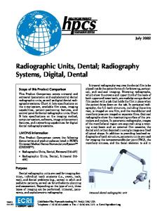
Fig. 1. The used a CCD78-20 intra-oral sensor in this system. This picture was provided by e2v technologies limited. Available at: http://www.e2vtechnologies.com/ccd78-20.pdf.
0-7803-8701-5/04/$20.00 (C) 2004 IEEE
The DDR system was developed using a CCD78-20 sensor (e2v technologies limited, Chelmsford, Essex, England), which is shown in Figure 1. It coated a Gd2O2S(Tb) scintillation film for X-ray detection. The CCD78-20 sensor had an active area of 20 × 30 mm2. The acquired images had a 912 × 1368 pixel matrix. Each effective pixel had a size of 22 × 22 µm2. It has a readout noise of 150 e- rms, gate protection structures and low noise output amplifier. The X-ray spectral range of this sensor was 15 ∼ 70 keV. The maximum clock frequency (one clock cycle per pixel) was 1 MHz [2]. In order to operate the CCD sensor, an electrical signal processing circuit was designed to analyze the input and output signals. The personal computer (PC) interface board was composed of an image signal amplifier, a read-out circuit, and an analog to digital converter to assess the timing diagrams on the CCD sensor. A FTDI (Future Technology Devices International Ltd., U.K.) chip was used to fabricate the universal serial bus (USB) board. A D2xx driver, which is provided by FTDI, consisted of a windows WDM driver, which communicates with the device via the windows USB Stack, and a DLL, which interfaces the applications software (written in VC++, C++ Builder, Delphi, VB etc) to the WDM driver. The electrical signal processing circuit box was also designed to provide a convenient interface between the PC and the CCD sensor. B. Graphic User Interface Software The graphic user interface software was coded using Microsoft Visual C++ language. The patient database program, using MS Access 97, was embedded into this software. By means of accessing the database program, the images can be searched by retrieving the patient’s image directories. The database window was updated in order to be ready to retrieve and process a new image, after indicating the existence of the existing stored images for the current patient in the database window. C. Image acquisition and evaluation of the system In this study, the X-ray exposures were made with a Heliodent MD D-70-p radiographic system (Siemens AG, Germany). The distances between the X-ray tube and the CCD sensor were adjusted at 20 cm for optimizing the image quality. In order to evaluate the image quality according to the variations in the dose, phantom images (60 kVp, 7 mA) were obtained at variable exposure times, provided the signal-tonoise ratio (SNR) of each images using a region of interest (ROI). The number of pixels in the ROI ranged from 750,000 to 780,000 pixels. The fundamental SNRs for digital radiographic systems are defined in terms of their detective quantum efficiency, noise power spectra, and modulation transfer function. The target SNR level of the used CCD sensor in this study, which means the response of the system, was 23. With the variable exposure conditions, the SNRs were measured.
A ROI was set for each image. The mean pixel values were measured and their standard deviations were calculated. The SNR was calculated as the ratio between the image forming signal (average pixel value) and the noise (standard deviation) using an IDL program (Research System Inc., Pearl Ease Circle Boulder, Co. USA). In this process, there was no brightness correction of the grayscale adjustment [3]-[5]. Step-wedge images were acquired in order to evaluate objectively the image contrast according to the variations in time. The thicknesses of the step-wedge were 1.02, 1.57, 2.06 and 2.58 mm. The step-wedge imaging method was used to obtain the modulation transfer function (MTF) of the DDR system. This is an alternative method for determining the MTF of a radiographic system that is to measure its edge spread function (ESF) using an opaque object with a sharp edge, a thin gold-nickel foil layer (of thickness 0.0175 mm), both vertically and horizontally. An ESF was obtained by scanning and averaging the pixel values from 20 line images in a direction orthogonal to the edge line. In order to reduce statistical fluctuation on both plateau sides of the raw data, the data was smoothed using adjacent averaging. The line spread function (LSF) was calculated from the derivative of the ESF. Finally, the MTF was calculated from the fast Fourier transform of the LSF and its zero-frequency value was normalized to 1.0 [6]-[8]. The conditions used for the image acquisition were 60 kVp, 7 mA, and 0.05 sec exposure time. The software used was Image-pro plus 4.0 (Media Cybernetics, 8484 Georgia Avenue Silver Spring, MD, USA), and Origin 6.0 (Microcal Software, Inc., Northampton, MA, USA), both being Windows Versions [9]-[10].
III. RESULTS A. Hardware System Fig. 2 shows the developed electrical signal processing circuit box. The 8 bits of 12 bits were used to transfer at once by a bus. The image data passing through the readout circuit of the detector system had been inverted to appear darker with increasing the exposure dose as is observed in traditional film based method.
Fig. 2. The developed electronic signal processing circuit box.
0-7803-8701-5/04/$20.00 (C) 2004 IEEE
The best focus was obtained at 20 ± 1 cm from the X-ray tube. The image quality obtained using a 0.05 sec exposure time provided the best visual quality, as shown in Fig. 3. The exposure time of the best visual quality was determined from the pixel values, which are dependent on the entrance X-ray intensity. These images were compensated as same contrast.
spatial resolution of this system was approximately 12 lp/mm in vertical and horizontal directions, respectively.
(a)
(a)
(b)
(c)
Fig. 3. Test pattern images acquired at 60 kVp, 7 mA, (a): 0.04, (b): 0.05, (c): 0.06 sec exposure time. These images compensated as same contrast.
(b)
The SNRs of the system were measured with variable exposure conditions until obtained the target SNR 23, which means the suitable response of the system at a certain level of radiation exposure with the associated noise generated. On this process, the target SNR 23 was measured at 194 µGy exposure dose and 60 kVp, 7 mA, 0.05 sec. Fig. 4 shows the results of measuring the SNRs of the system. (c) Fig. 5. Step-wedge images acquired at 60 kVp, 7 mA, (a): 0.04, (b): 0.05, (c): 0.06 sec exposure time. These images were not compensated.
Fig. 4. The calculated results of the SNRs of the system were showed. The target SNR level 23 was measured at 194 µGy exposure dose.
The archived step-wedge images at each level of the X-ray exposure time showed in Fig. 5. These images were not compensated. Fig. 6 presents the calculated MTFs from the LSF and ESF of the step-wedge images. Thus, the spatial resolution was measured at a 10% contrast in terms of the corresponding MTF values [6]. The result shows that the
Fig. 6. Modulation Transfer Function (MTF) shows that spatial resolution is approximately 12 lp/mm in vertical and horizontal directions.
B. Graphic User Interface Software The image data transferred from the USB port was in an 8bit grayscale format and this raw data was converted to the various image formats (bmp, jpeg, tiff, etc) by the user
0-7803-8701-5/04/$20.00 (C) 2004 IEEE
interface software. Image manipulation, which includes the interactive image contrast and brightness control, image rotation and flip, spatial image filtering, and zooming in on an area of interest, can be activated from the database window. Fig. 7 shows the several sample windows of the developed graphic user interface software.
absorbed dose, the reduced dose effect of the developed DDR system compared to conventional film based method under the similar conditions.
(a) (a)
(b)
(c)
(d)
Fig. 7. The several sample windows of this system. (a): patient’s information, (b): dental clinic mode, (c): comparison of the images, (d): image analysis.
C. Image acquisition and Dose effects The human phantom images were acquired by the developed DDR system and the traditional film based method, as shown in Fig. 8. For DDR system, the phantom image acquired at 60 kVp, 7 mA, 0.05 sec and the measured absorbed dose was 194 µGy. A traditional film based image acquired at 70 kVp, 7 mA, 0.1 sec, which are the conventional clinical conditions. At this time, the absorbed dose of the film based method measured at 468 µGy. Except the power of Xray tube, all image acquisition conditions were same. IV. DISCUSSION AND CONCLUSION In this study, we have developed a DDR system using a high resolution CCD sensor and a graphical user interface (GUI) to acquire and display intra-oral images. The image display software and the patient database program were also developed using Microsoft Visual C++ language and MS Access 97, respectively. The imaging characteristics were evaluated quantitatively using the digital images obtained by transforming the electrical signals generated by the CCD sensor and using a signal processing board developed for interfacing between the CCD and PC. The MTF and SNRs were measured and evaluated for their imaging characteristics of the DDR system. In order to confirm the reduction of X-ray
(b)
(c)
Fig. 8. The human phantom images acquired from the developed DDR and traditional film based systems. (a): human phantom, (b): image from the developed DDR system, (c): scanned image from the film based method.
The spatial resolution of the developed DDR system in this study measured by a MTF was approximately 12 lp/mm. The theoretical limitation of the spatial resolution of this DDR system using the CCD sensor with a pixel size of 22 × 22 µm2 is approximately 22 lp/mm. In general, the limitation in the spatial resolution was determined according to the selected Xray detector pixel size. In spite of that, the system spatial resolution of the developed CCD system measured 12 lp/mm, which is 55% of the theoretical limitation. The spatial resolution of the DDR system derived directly from the image itself depends on the X-ray source, the image acquisition parameters, the image manipulation, and the physical characteristics of the object. These various parameters can be the causes of the degradation of the system spatial resolution. According to provided a manual from the manufacture of the CCD sensor, it can present the spatial resolution of maximum 16 lp/mm. In this system, the target SNR, which means the optimal dose response of the digital radiographs, was 23 at an exposure dose of 194 µGy. At this time, the X-ray source generated at 60 kVp, 7 mA and 0.05 sec exposure time. In the lower level than the target SNR, the image in Fig 3(a) appears to be slightly blurred. But, at the high level than the target SNR, the image shows to be getting dark and then the pixels of the CCD sensor became saturated due to overexposure.
0-7803-8701-5/04/$20.00 (C) 2004 IEEE
Finally, the target SNR 23, as shown in Fig 3(b), provides the best visual quality. The conventional dental films currently available have a spatial resolution of approximately 12 lp/mm. Under the commonly dental clinical conditions, the developed DDR system reduced the X-ray absorbed dose to 41% of the filmbased system. The developed DDR system, which have a similar spatial resolution compared with the conventional dental films, definitely provides the reduction of the X-ray absorbed dose. For that reason, the DDR system has many benefits compared to film based methods, such as a low dose, real time acquisition, no chemical processing, image storage and retrieval, and improving the clinical work flow in a hospital environments. Furthermore as the number of PACS installations in dental clinic has recently been increasing, the demand for the DDR system has rapidly increased in the dental radiological field. In conclusion a DDR system using a high resolution CCD sensor was developed and the imaging characteristics of the system were evaluated. The results in this study demonstrated that the DDR system could be potentially applied for dental clinical use.
REFERENCES [1]
S. Hong, H. Jung, K-D. Kim, S-G. So, J-H. Kim, S. K. Yoo, H. S. Yoo, H-J. Kim, “Development and Evaluation of a CMOS Sensor Based Digital Intra-oral Radiographic System,” IEEE TNS, submitted for publication. [2] E2V technologies, Digital Intra-Oral X-ray Dental Sensor (CCD78-20), e2v technologies limited, 2003. [3] Y. Hayakawa, A. G. Farman, M. S. Kelly, K. Kuroyanagi, “Intraoral radiographic storage phosphor image mean pixel values and signal-tonoise ratio,” Oral Surg Oral Med Oral Pathol Oral Radiol Endodo, vol. 86, pp. 601-605, 1998. [4] A. G. Attaelmanan, E. Borg, H. G. Grondahl, “Signal-to-noise ratios of 6 intraoral digital sensors,” Oral Surg Oral Med Oral Pathol Oral Radiol Endodo, vol. 91, pp. 611-5, 2001. [5] U. Welander, P. Nelvig, G. Tronje, W. D. McDavid, S. B. Dove, A. C. Morner, T. Cederlund, “Basic technical properties of a system for direct acquisition of digital intraoral radiographs,” Oral Surg Oral Med Oral Pathol, vol. 75, pp. 506-16, 1993. [6] H. Jung, H. J. Kim, S. Hong, J. O. Hong, H. K. Jeong, H. J. Jung, B. R. Kim, H. S. Yoo, “Computed Microtomography (µCT) with Unmonochromatized Synchrotron X-rays for Cancerous Human Breast Tissue and Mouse Vertebra,” IEEE TNS, vol. 49, pp. 5-10, 2002. [7] E. Samei, M. J. Flynn, D. A. Reimann, “A method for measuring the presampled MTF of digital radiographic systems using an edge test device,” Med. Phys, vol. 25(1), pp. 102-13, 1998. [8] M. Salome, F. Peyrin, P. Cloetens, C. Odet, AM. Laval-Jeantet, J. Baruchel, P. Spanne, “A synchrotron radiation microtomography system for the analysis of trabecular bone samples,” Med. Phys, vol. 26(10), pp. 2194-204, 1999. [9] A. Kenneth, J. Fetterly and Nicholas, Hangiandreou, “Image quality evaluation of a desktop computer radiography system,” Med. Phys, vol. 27(12), pp. 2669-79, 2000. [10] W. Huda, L. N. Rill, D. K. Benn, J. C. Pettigrew, “Comparison of a photostimulable phosphor system with film for dental radiology,” Oral Surg Oral Med Oral Pathol Oral Radiol Endodo, vol. 83, pp. 725-31, 1997.
0-7803-8701-5/04/$20.00 (C) 2004 IEEE